1. Introduction
The global energy landscape is undergoing a profound transformation driven by the imperative to reduce carbon emissions and enhance energy security. Distributed energy resources (DERs), particularly PV systems integrated with battery storage, have emerged as pivotal components in this transition toward sustainable energy systems. Unlike conventional centralized power generation, these distributed systems offer numerous advantages, including reduced transmission losses, enhanced grid resilience, and the ability to harness locally available renewable resources [
1,
2,
3].
Grid-connected PV–battery systems represent a sophisticated configuration of DERs that enable bidirectional power flow between local generation assets and the utility grid. These systems typically comprise PV arrays, power conversion equipment, battery energy storage systems (BESSs), and advanced control infrastructure [
4,
5,
6]. The integration of battery storage with PV generation addresses one of the fundamental challenges of solar energy: its intermittent and variable nature. Batteries serve as energy buffers, storing excess generation during periods of high solar irradiance for use during low-generation periods or peak demand times [
7,
8]. Recent advancements in battery technology, particularly lithium-ion chemistries, have significantly enhanced the technical and economic viability of integrated PV–battery systems. Concurrently, declining costs of both PV modules and battery storage have accelerated the deployment of these systems across residential-, commercial-, and utility-scale applications [
1,
9]. As noted by [
4], over the past decade, the cost of PV systems for residential use has significantly dropped, making them increasingly accessible for distributed deployment. However, the effective integration of PV battery systems with the existing grid infrastructure presents significant technical challenges. These include maintaining voltage stability, managing bidirectional power flows, ensuring power quality, and coordinating with traditional grid operations [
7,
9,
10]. The intermittent nature of solar generation introduces uncertainty in power availability, necessitating sophisticated forecasting and control strategies to ensure reliable system operation [
5,
11,
12].
EVs represent another transformative element in the evolving energy ecosystem. Beyond their primary function as transportation assets, EVs equipped with substantial battery capacity can serve as mobile energy storage units capable of interacting with the grid in sophisticated ways [
13,
14,
15]. This bidirectional interaction manifests in two primary modes, namely G2V, where the grid supplies power to charge the EV battery, and V2G, where the EV battery discharges power back to the grid [
7,
10,
16]. The G2V mode represents the conventional charging paradigm, where EVs draw power from the grid to replenish their batteries. Uncoordinated EV charging can exacerbate peak demand issues, potentially straining grid infrastructure and necessitating costly upgrades [
5,
7]. Conversely, the V2G mode transforms EVs from mere loads to active participants in grid operations. By discharging stored energy back to the grid during peak demand periods or grid contingencies, EVs can provide valuable services, including peak shaving, frequency regulation, and voltage support [
10,
15,
16].
The integration of EVs with grid-connected–battery systems creates a synergistic relationship that can enhance the value proposition of both technologies. As highlighted by [
15], EVs can serve as flexible energy storage systems that mitigate the impacts of high PV penetration while simultaneously benefiting from low-cost renewable charging. This integration enables several operational strategies:
Solar-powered EV charging: Directly utilizing PV generation to charge EVs, reducing grid dependency and associated emissions [
11,
17].
Load shifting: Charging EVs during periods of excess PV generation and discharging during peak demand or low generation periods [
7,
10].
Grid services provision: Leveraging aggregated EV battery capacity to provide ancillary services to the grid, potentially generating revenue streams for EV owners [
15,
16].
Resilience enhancement: Using EV batteries as backup power sources during grid outages, particularly when integrated with local PV generation [
10,
14].
However, the effective implementation of V2G/G2V operations faces several challenges. These include battery degradation concerns, complex coordination requirements, communication infrastructure needs, and regulatory barriers [
5,
7,
10]. Moreover, the stochastic nature of both EV availability (dependent on user behavior) and PV generation (dependent on weather conditions) introduces significant uncertainty in system operations [
11,
15].
The complexity of managing integrated energy systems with multiple assets, bidirectional power flows, and various operational constraints necessitates advanced control strategies. Model predictive control (MPC) has emerged as a particularly effective approach for energy management in such systems [
3,
18,
19]. MPC is a model-based control technique that uses a system model to predict future behavior over a finite horizon and computes optimal control actions by solving a constrained optimization problem [
20,
21]. In the context of grid-connected PV–battery systems with V2G/G2V capabilities, MPC offers several compelling advantages, as follows:
Anticipatory control: By incorporating forecasts of PV generation, load demand, and electricity prices, MPC can make proactive decisions rather than merely reacting to current conditions [
3,
9].
Constraint handling: MPC naturally accommodates various operational constraints, including battery state-of-charge limits, power flow constraints, and grid interconnection requirements [
18,
20].
Multi-objective optimization: The MPC framework can balance multiple potentially competing objectives, such as maximizing renewable utilization, minimizing operating costs, and reducing battery degradation [
19,
21].
Adaptability: MPC can adapt to changing system conditions, including variations in PV generation, load profiles, and grid states [
9,
20].
Several studies have demonstrated the efficacy of MPC for energy management in grid-connected systems. For instance, [
3] developed a decentralized energy management system using MPC to regulate energy flow among PV systems, batteries, and the grid for efficient EV charging. Similarly, [
9] presented a model-based control strategy to address the challenge of locally balancing power supply and demand in a grid-connected microgrid. However, conventional MPC-based approaches face limitations when applied to systems with significant uncertainty and nonlinearity, such as integrated PV–EV systems. These limitations include model mismatch issues, computational complexity for real-time implementation, and challenges in accurately forecasting renewable generation and load demand [
19,
20]. Furthermore, the performance of MPC heavily depends on the accuracy of the underlying system model, which can be challenging to obtain for complex, heterogeneous energy systems [
18,
21].
The limitations of conventional MPC approaches have motivated the integration of artificial intelligence techniques, particularly neural networks (NNs), to enhance controller performance [
11,
19,
20]. The adaptive nature of NNs allows the controller to learn from operational data and improve performance over time, addressing the challenges associated with the stochastic nature of renewable generation and EV availability [
10,
11,
19]. The integration of NNs with MPC, often termed NN-MPC, can take several forms, as follows:
System identification: NNs can be trained to model the dynamics of complex systems, providing more accurate predictions for the MPC framework [
19,
20].
Load and generation forecasting: NNs can more accurately predict future PV generation, EV charging demand, and grid conditions than traditional statistical methods [
10,
11].
Control policy approximation: NNs can approximate complex control policies, potentially reducing the computational burden of solving optimization problems in real time [
19,
20].
Adaptive parameter tuning: NNs can continuously adapt MPC parameters based on observed system behavior and performance metrics [
20].
Several studies have explored the application of NN and MPC in energy management and control systems. For instance, [
11] proposed a neural network-trained energy management strategy for PV-powered EV charging with battery storage, focusing on load and generation forecasting. However, it lacked integration with real-time predictive control, which limits its adaptability under dynamic operating conditions. In [
19], the authors provided a comprehensive review of AI-enhanced predictive energy management systems, highlighting the benefits of integrating machine learning techniques with traditional control approaches. However, the work remained theoretical, as it neither proposed nor validated a unified control framework. Meanwhile, Ref. [
20] developed an effective nonlinear MPC scheme tuned by improved NNs, demonstrating enhanced performance in handling system nonlinearities and uncertainties compared to conventional approaches. However, this approach was domain-specific to robotics and did not address forecasting, energy coordination, or bidirectional power flow. An intelligent energy management controller for a smart DC microgrid, integrating fuzzy logic and fractional-order PID (FO-PID) methods, was presented in [
22] to optimize power extraction from hybrid renewable sources (wind, PV, and battery bank) while prioritizing cost-effectiveness and power quality. The controller ensured smooth output and service continuity, with simulation results under MATLAB/Simulink demonstrating superior performance. While [
21] enhanced energy management using FO-PID and fuzzy logic in hybrid wind/PV/battery systems, it lacked predictive control and neural network integration. Additionally, it did not address EV participation, bidirectional power flow, or dynamic grid coordination. Our proposed NN-MPC framework overcomes these limitations by combining forecasting with real-time optimization to manage G2V/V2G operations in PV–battery–EV systems.
Despite these advancements, the integration of NNs with MPC for bidirectional power flow management in PV–EV systems remains relatively unexplored. Most existing studies focus on either prediction enhancement or control policy approximation, with limited consideration of comprehensive NN-MPC frameworks that address both aspects [
11,
19,
20]. Additionally, the real-time implementation of NN-MPC in systems with multiple assets and objectives requires further investigation [
10,
20]. Based on the literature review, the following research gaps can be identified:
Limited integration of V2G/G2V with NN-MPC: While there are studies that address V2G/G2V operations and others that explore NN applications in energy management, the specific integration of NN-MPC with bidirectional V2G/G2V operations remains relatively unexplored. Only a few papers discuss all three aspects together, and none provide a comprehensive framework for seamless bidirectional power flow management using NN-MPC.
Insufficient real-time optimization: Few papers specifically address the challenges of real-time control and optimization for grid-connected PV–battery systems with bidirectional power flow capabilities. The computational complexity of conventional MPC approaches and the need for accurate, adaptive models in dynamic environments represent significant challenges that have not been adequately addressed.
Limited focus on bidirectional power flow challenges: While many papers discuss either V2G or G2V operations, few specifically address the challenges associated with managing bidirectional power flow, including battery degradation concerns, power quality issues, and coordination requirements.
Lack of comprehensive system integration: Most existing studies focus on specific components or subsystems rather than providing comprehensive frameworks for integrating PV generation, battery storage, EV charging/discharging, and grid interaction in a cohesive, optimized system.
Insufficient consideration of uncertainty: The stochastic nature of both PV generation and EV availability introduces significant uncertainty in system operations. While some studies address forecasting and prediction, few provide robust approaches for handling uncertainty in bidirectional power flow management.
Despite extensive research on grid-connected PV–battery systems and EV charging, most solutions fail to integrate V2G and G2V functionalities within a unified, intelligent control framework. This study aims to fill this gap by developing an NN-MPC system capable of real-time bidirectional energy coordination, reducing grid stress while maximizing renewable energy utilization.
Addressing the identified research gaps, this paper aims to develop a comprehensive framework for grid-connected PV–battery systems with V2G/G2V capabilities using NN-MPC. The specific objectives of this research include the following:
Developing an integrated NN-MPC framework: Design a control architecture that integrates NNs with MPC for optimizing bidirectional power flow in grid-connected PV–battery–EV systems.
Simulating mode transitions: Create a control strategy that enables seamless transitions between V2G and G2V modes based on PV availability and system state conditions.
Enhancing predictive control performance: Leverage the forecasting capabilities of NNs to improve the effectiveness of MPC for real-time implementation in systems with multiple energy assets.
Addressing bidirectional power flow challenges: Develop strategies for mitigating battery degradation, maintaining DC bus voltage stability, and ensuring effective energy coordination for multiple energy sources with bidirectional power flow capabilities.
Validating system performance: Demonstrate the effectiveness of the proposed approach through comprehensive simulations under various operational scenarios and environmental conditions.
The primary contributions of this research are as follows:
NN-MPC control architecture: A novel simulation-based framework that integrates NNs with MPC is designed for bidirectional power flow management in grid-connected PV–battery–EV systems.
Mode-based bidirectional control strategy: A strategy that enables seamless transitions between V2G and G2V modes based on dynamic system conditions, optimizing multiple objectives, including renewable utilization, grid dependency, and battery lifetime.
Enhanced prediction framework: An NN-based model that improves the accuracy of forecasting for PV generation, EV charging demand, and grid conditions for MPC implementation.
Comprehensive system integration: A holistic approach to integrating PV generation, battery storage, EV charging/discharging, and grid interaction in a cohesive, optimized system.
Practical implementation insights: Valuable insights into the practical implementation of NN-MPC for bidirectional power flow management, including computational considerations, parameter tuning, and performance evaluation.
By addressing these objectives and delivering these contributions, this research aims to advance the state of the art in renewable energy integration with electric vehicles and provide a promising solution for future smart grid applications that require sophisticated bidirectional power management capabilities. The novelty of this work lies in the integration of neural network-based forecasting with model predictive control for the unified, real-time management of G2V and V2G operations. Unlike existing methods, it optimizes system-wide energy flow with predictive foresight and adaptive learning, enhancing efficiency.
The remainder of the paper is organized as follows.
Section 2 gives an overview of the PV system, battery storage, and bidirectional converter control, explaining their roles in energy management.
Section 3 introduces the NN-MPC methodology, with a particular emphasis on its implementation for EV battery control in the charging station.
Section 4 presents the simulation results and discussion, analyzing system performance under different operating conditions and validating the effectiveness of the proposed control strategy. Finally,
Section 5 concludes the paper by providing key findings and future research for improving energy management in PV-integrated electric vehicle charging stations.
2. Structure of the Proposed Scheme
This section provides the details of the proposed system architecture and modeling of its respective components.
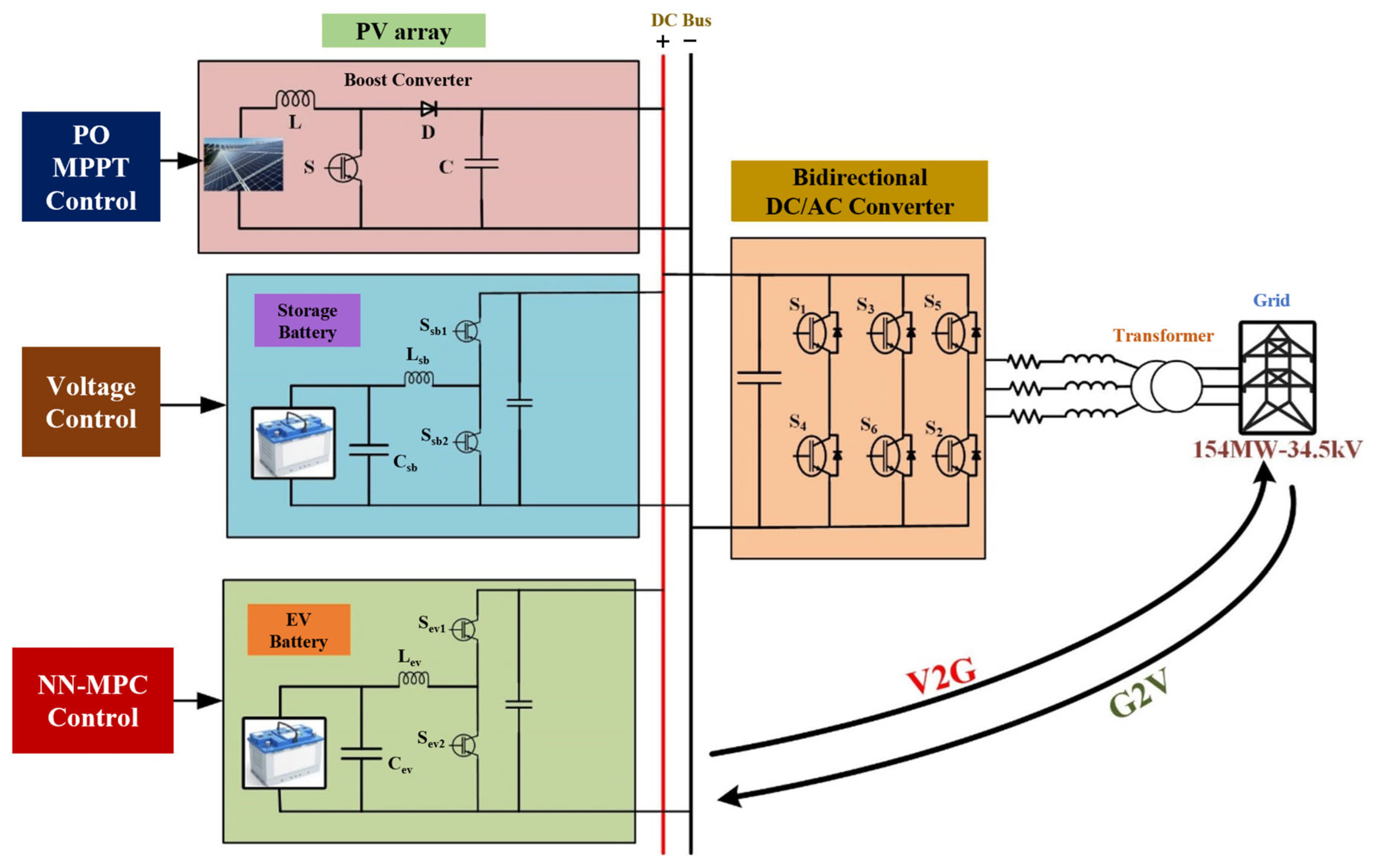
Figure 1 depicts a smart energy management system (EMS) comprising a PV array, storage battery, EV battery, and grid connection. The diagram illustrates the complete power flow architecture with detailed circuit components and control mechanisms. At the top of the diagram, the PV array connects to a boost converter that includes an inductor (L), diode (D), switch (S), and capacitor (C). This converter is controlled by a perturb and observe (P&O) maximum power point tracking (MPPT) control algorithm, which optimizes the power extraction from the solar panels under varying environmental conditions. In the middle section, the storage battery system features a bidirectional converter with switches (S
sb1, S
sb2) and components, including an inductor (L
sb) and capacitor (C
sb).
This subsystem is managed by a voltage control mechanism that maintains stable voltage levels and ensures consistent energy flow throughout the system. The subsection shows the EV battery subsystem with a similar configuration to the storage battery, including switches (Sev1, Sev2), an inductor (Lev), and a capacitor (Cev). What distinguishes this subsystem is its advanced NN-MPC strategy, which optimizes the charging and discharging dynamics of the EV battery based on predicted conditions and multiple objectives. All three subsystems connect to a central DC bus, which serves as the power exchange backbone of the system. On the right side, a bidirectional DC/AC converter with six switches (S1–S6) connects the DC bus to the grid through a transformer. This converter enables power flow between the DC components and the AC grid at 154 MW-34.5 kV.
Figure 1 clearly illustrates the bidirectional power flow capabilities, with arrows showing V2G and G2V operations. This integrated approach creates a flexible and sustainable power management system that enhances grid stability, improves energy efficiency, and maximizes renewable energy utilization by allowing EVs to either return surplus stored energy to the grid or use grid power for charging as needed.
Table 1 presents the key parameters of the proposed PV–battery–EV system implemented in MATLAB/Simulink.
2.1. PV Model and MPPT Control
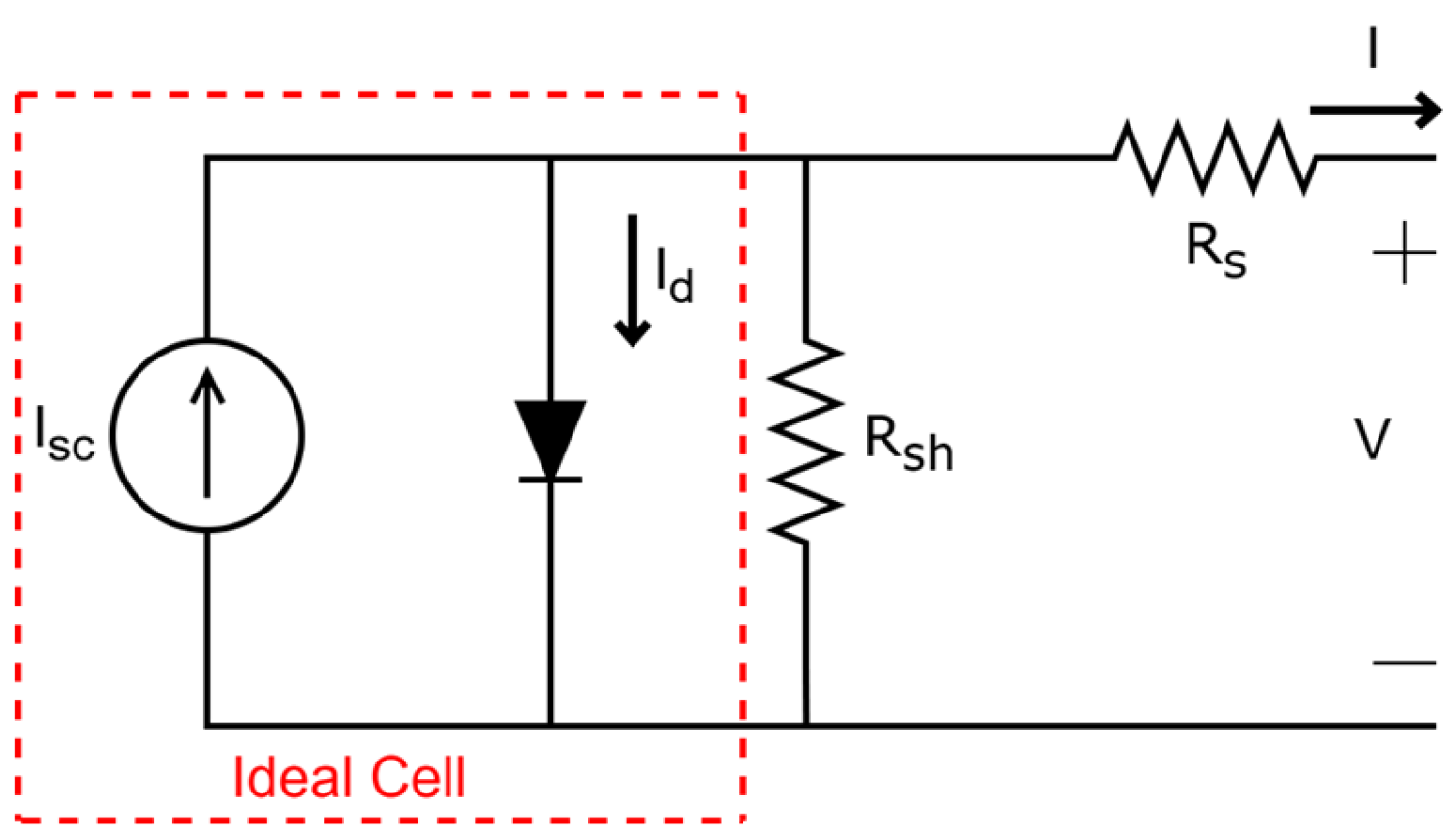
The photoelectric impact of a PN junction is the fundamental working principle of a PV array. When photons with sufficient energy strike the PN junction, electron–hole pairs are generated, creating a potential difference across the junction. This PV effect forms the basis for solar energy conversion in PV cells. An analogous electrical circuit can be used to describe the physical phenomena of the PV module. The standard one-diode model, widely accepted for its balance between accuracy and computational simplicity, consists of a current source (representing the photogenerated current), a parallel diode (representing the PN junction), a parallel resistor (representing the leakage current), and a series resistor (representing internal losses).
Figure 2 shows the equivalent model of the PV cell.
The load current is expressed by the following Equation (1), which represents the fundamental current balance in the circuit:
where
is the terminal current,
is the short-circuit current,
is the diode current, and
is the shunt current. Expanding this equation to incorporate the diode characteristics and Ohm’s law for the shunt resistance path yields the following Equation (2):
where
is the diode saturation current,
is the terminal voltage,
is the intrinsic series resistance,
is the intrinsic shunt resistance,
is the diode ideality factor (typically between 1 and 2),
is the Boltzmann constant (
J/K),
is the cell temperature in Kelvin,
is the electron charge (
C), and
is the number of cells connected in series within the module. This equation captures the nonlinear I–V characteristics of the PV module and serves as the foundation for performance analysis under varying environmental conditions.
The model’s current source is based on the temperature as well as the amount of solar irradiation, which are the main factors influencing the electrical output of the module. The short-circuit current is given by the following Equation (3):
where
is the short-circuit current at standard test conditions (STC: 1000 W/m
2, 25 °C),
is the solar radiation quantity in W/m
2,
is the temperature coefficient of short-circuit current (A/°C),
is the cell temperature in Celsius, and
is the reference temperature (typically 25 °C). The short-circuit current exhibits a predominantly linear relationship with irradiance while showing a relatively minor dependence on temperature. Conversely, the open-circuit voltage is significantly affected by temperature variations, decreasing with increasing temperature according to the following Equation (4):
where
is the open-circuit voltage at STC and
is the temperature coefficient of the open-circuit voltage (V/°C). Variations in temperature have a more significant influence on the PV module’s output voltage than variations in irradiation do on its output current. Since the output power’s variable range at different temperatures is narrow, irradiation variation plays a significant role in the PV array’s output power.
The power output of a PV module is the product of its current and voltage, as in the following Equation (5):
The P–V curve of a PV module exhibits a single maximum point, known as the maximum power point (MPP), where the product of current and voltage reaches its peak value. This point represents the optimal operating condition for the PV module, maximizing the energy harvest. The location of the MPP on the P–V curve varies with changing environmental conditions. Increasing irradiance levels shift the MPP upward (higher power) while maintaining a relatively similar voltage. Temperature increases, however, shift the MPP leftward (lower voltage) and slightly downward (lower power), reducing overall efficiency. This dynamic behavior of the MPP necessitates active tracking mechanisms to ensure optimal energy extraction from PV systems under varying environmental conditions, leading to the development of MPPT algorithms.
Table 2 shows the electrical characteristics of the PV module.
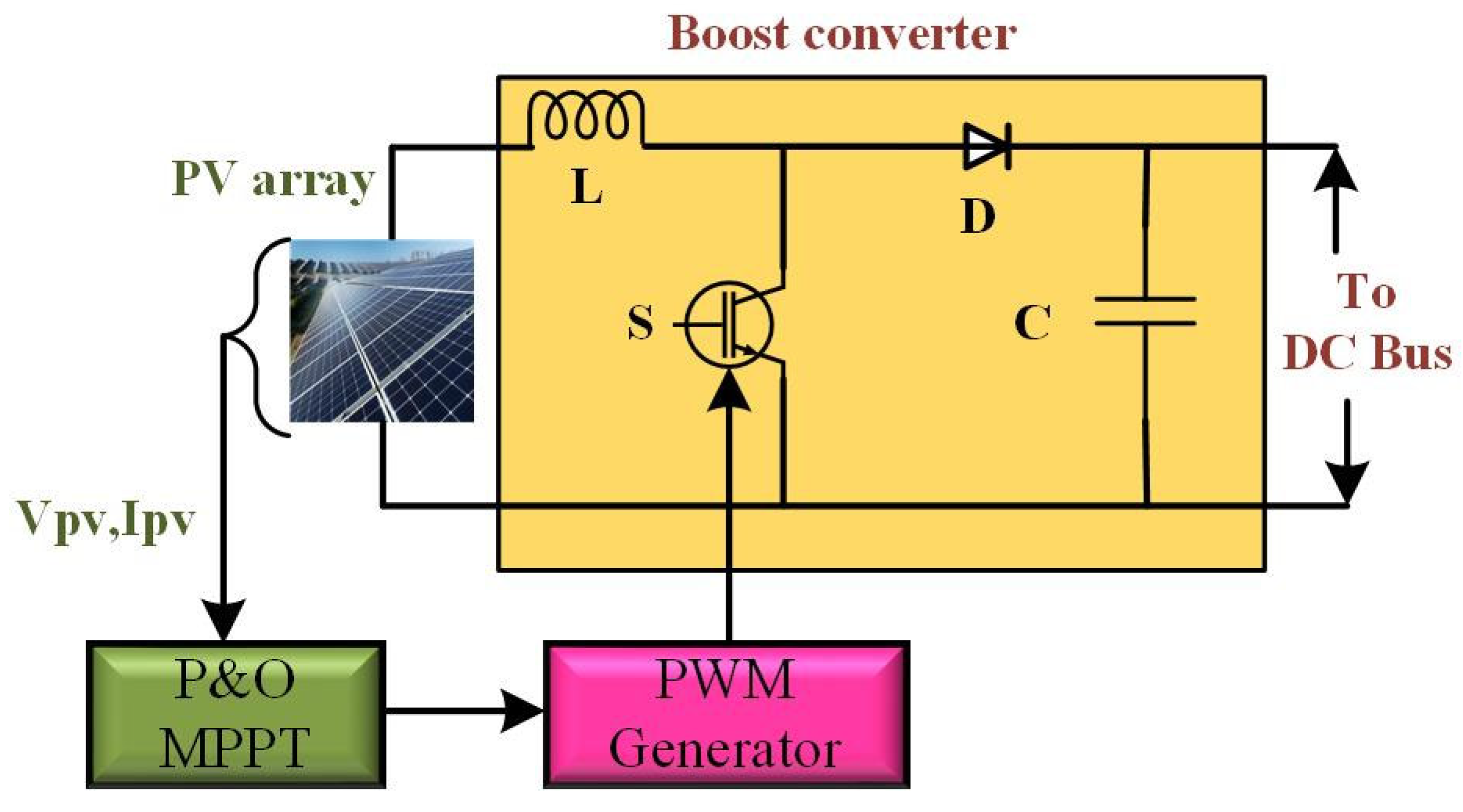
An energy management system (EMS), including a PV module, a boost regulator, and an MPPT control mechanism, is depicted in
Figure 3. Using the DC power produced by the PV array, the boost regulator increases the voltage to the necessary DC bus level. The boost regulator stabilizes the output voltage while ensuring maximum power extraction from the PV array. The boost converter topology consists of an inductor, a power switch (typically a MOSFET), a diode, and an output capacitor [
23]. The converter operates in two states, as follows:
ON state: When the switch is closed, the inductor current ramps up, storing energy.
OFF state: When the switch is opened, the stored energy in the inductor is transferred to the output capacitor through the diode.
The relationship between input and output voltage is governed by the following Equation (6):
where
is the duty cycle of the switching signal. The system’s governing P&O MPPT algorithm finds the PV module’s ideal working point to maximize power extraction. The MPPT signal is transformed into a switching pulse for the boost regulator switch by a PWM generator, which also regulates the duty cycle of the pulse to change the output voltage as needed. The fundamental principle of P&O is based on the hill climbing concept, where the operating point is perturbed in a specific direction, and the resulting change in power is observed to determine subsequent perturbations.
2.2. Storage Battery with Voltage Control
The battery is represented by a controlled source linked to a series resistance, and the battery’s equivalent circuit is derived using a nonlinear equation. The battery characteristics of this type exhibit comparable behavior when charging and discharging. The open voltage source E is calculated using a nonlinear function depending on the battery’s actual SOC to ascertain the no-load voltage. Equations (7) and (8) represent the generic battery model equations, as follows:
The battery model is characterized by several key parameters. Here,
E represents the no-load voltage source, while
is the voltage of the battery. The polarization voltage constant
K and the battery capacity
Q are also critical in defining the battery’s behavior. The real battery charge, which is a measurement of the cumulative current over time, is represented by the integral ∫i dt. The nonlinear features of the battery are described by the exponential voltage zone amplitude A and the exponential constant inverse capacity B. The battery’s internal resistance also affects how well it performs, and the voltage is shown by
Vbatt, while the current passing through the battery is represented by
i (A). When combined, these variables offer a thorough foundation for simulating the electrical behavior of the battery.
Figure 4 represents a bidirectional regulator for battery EMS that uses a PI controller and PWM generator to regulate the power flow. The converter enables bidirectional power transmission between the battery and the DC bus. During charging, the battery stores excess power from the DC bus, and during discharging, it supplies power to the DC bus. The PI controller ensures that the V
dcbus remains constant by comparing it to a V
dcbusref and generating the appropriate control signal. The bidirectionality of the converter enables dynamic energy balancing, making it suitable for application in RESs.
2.3. Bidirectional DC–AC Converter Control
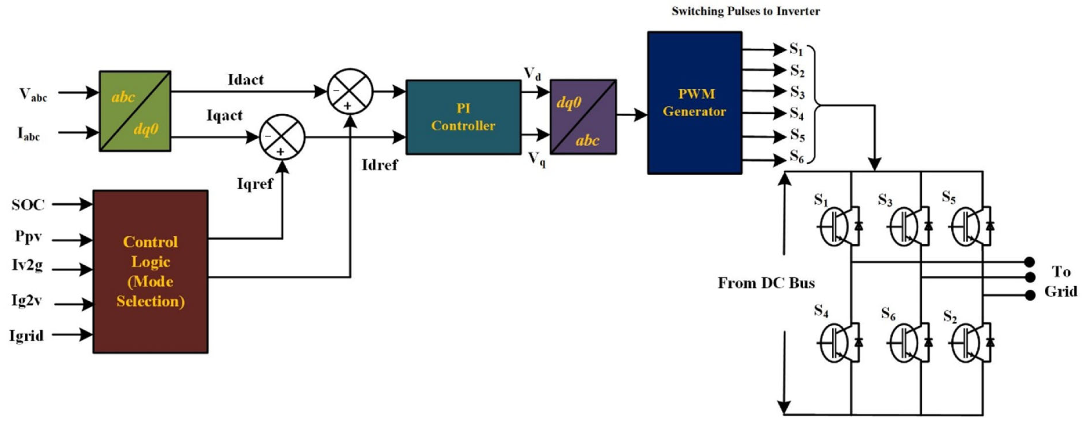
A bidirectional DC–AC converter, shown in
Figure 5, allows power transfer between an AC grid and a DC bus. A PWM generator drives the system’s three-phase inverter, which receives switching pulses for the six inverter switches. In this work, the PWM switching frequency is set to 10 kHz. When necessary, the converter facilitates grid-to-battery charging and permits bidirectional power flow, allowing surplus power from batteries or renewable energy sources to be injected into the grid. Active and reactive power regulation is made simpler by the control scheme’s use of a dq0 transformation block, which transforms three-phase abc voltages and currents into direct-quadrature dq components.
By comparing the Iqact and reference Iqref currents, the system uses a PI controller to control the current and guarantee steady operation. The operational mode is determined by a control logic block that dynamically switches among (V2G) Iv2g and (G2V) Ig2v modes based on such parameters as the SOC, PV power (Ppv), and grid current (Igrid). Before being delivered to the PWM generator, the regulated voltage outputs Vd and Vq undergo an inverse dq0 transformation to return to three-phase signals. The following section details the NN-MPC control for electric vehicles.
3. NN-MPC Control for EVs
A detailed analysis of the NN-MPC and its control is explained in this section. MPC is used to solve a numerical optimization problem. This control strategy has gained significant attention due to its ability to handle complex systems with multiple constraints and objectives. However, the implementation of MPC faces substantial challenges, particularly when applied to nonlinear systems. Due to the complexity of nonlinear control problems, it is often necessary to employ computational or approximative methods to find solutions.
One strategy to address computational challenges and reduce the real-time computational burden is to describe the optimum control rule using offline function approximators, such as NNs [
24]. This approach leverages NNs’ powerful approximation capabilities to capture complex system dynamics and control relationships. NNs have demonstrated the best performance among various function approximation techniques in the development and management of dynamic systems. Their ability to learn complex, nonlinear relationships from data makes them particularly suitable for modeling and controlling nonlinear systems. In particular, the multilayer perceptron is a popular choice for modeling nonlinear systems and implementing nonlinear controllers. Two-layer networks typically use sigmoid functions in the hidden layer and in the output layer, providing the necessary nonlinear mapping capabilities.
The concept of NN forms the foundation of NN-MPC. This approach integrates the predictive and constraint-handling capabilities of MPC with the powerful function approximation abilities of NNs. To forecast future plant performance, NN-MPC uses an NN model of a nonlinear plant. This NN is trained to capture the input–output relationships of the system, effectively serving as an alternate model that can predict system behavior under various operating conditions. The controller then determines the control input that maximizes plant performance over a certain future time horizon. This optimization process uses the NN model to predict how the system will respond to different control inputs, allowing the controller to select the input sequence that best achieves the desired objectives while respecting system constraints. The NN training data comes from the system’s nonlinear model or from actual operational data. The computational burden during real-time operation is significantly reduced by training the NN offline, as the online component primarily involves forward propagation through the NN and a simplified optimization process. A numerical optimization software uses the NN model’s predictions of the plant’s reaction across a specified time horizon to identify the control signal that reduces the working criteria for that time horizon. This approach maintains the core principles of MPC while addressing its computational limitations through the use of NN approximations.
The NN-MPC design process is delineated by the following steps:
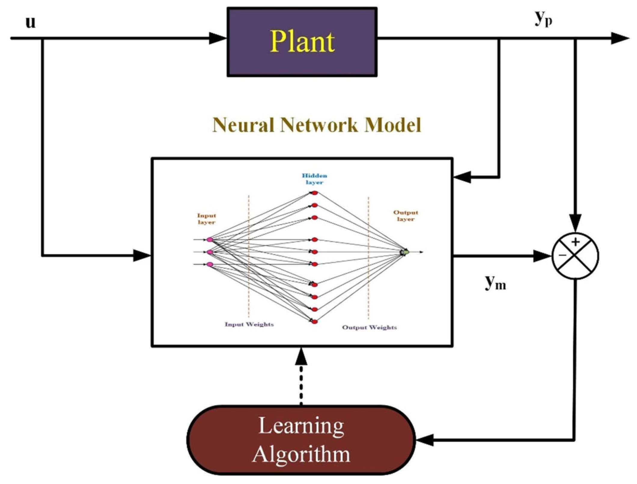
Neural network training: Training a neural network (NN) to simulate the plant’s forward dynamics is the initial step in the NN-MPC design. The NN receives the same control input as the actual plant and produces a predicted output y
m. The training signal—defined as the error between the NN output and the actual plant output y
p—is used to adjust the network’s weights. This iterative process continues until the NN accurately captures the plant’s dynamic behavior.
Figure 6 illustrates the flowchart of the NN training process for plant modeling.
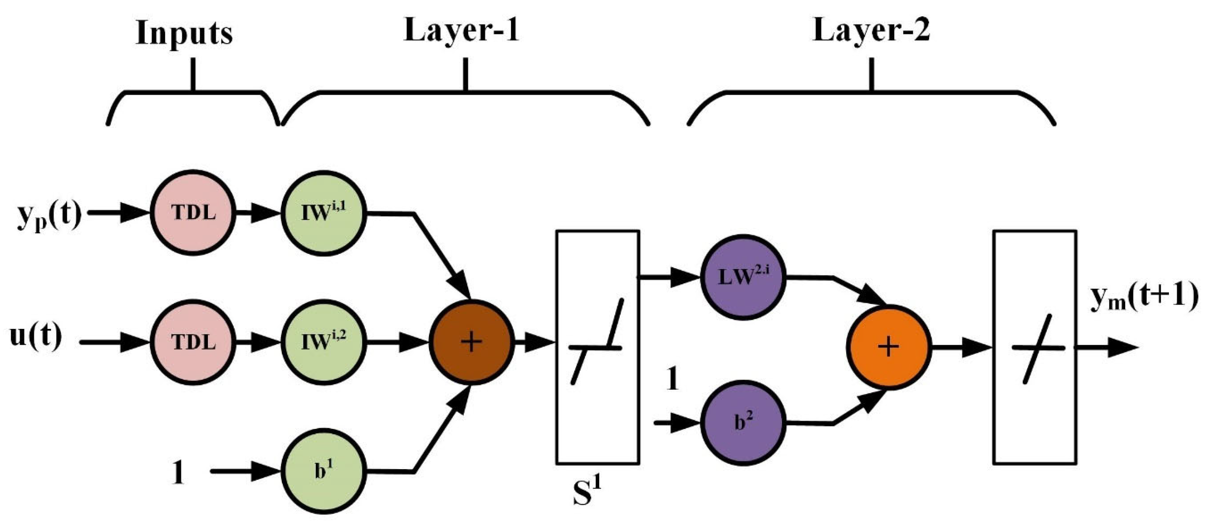
Figure 7 illustrates the architecture of a typical two-layer feedforward NN used for modeling nonlinear plant dynamics in NN-MPC. The network receives delayed versions of the plant output y
p(t) and control input u(t), processed through time delay lines (TDLs). In the first layer, weighted inputs are combined with biases and passed through a nonlinear activation function S
1. The resulting signals are then refined by the second layer to produce the predicted output y
m(t + 1).
Any of the training algorithms covered in multilayer shallow NNs and backpropagation training can be used to train this network offline in batch mode using data gathered from plant operations.
Predictive control: The MPC approach, which is based on the receding horizon methodology, uses an NN model that anticipates the plant reaction to determine the signal that minimizes the subsequent performance criterion across a specified time horizon.
Cost function definition: To implement the predictive control strategy, a cost function
J is defined to minimize both the tracking error and the control effort over the prediction horizon, ensuring a balance between performance and control smoothness [
25]. Equation (9) is as follows:
where N
1, N
2, and N
u stand for the horizons across which the tracing error and the control advances are evaluated. The preliminary control signal is represented by
u′, the intended response by y
r, and the network model response by y
m. The weighting factor
ρ indicates how much the sum of the squares of the control levels contributes to the performance index.
Optimization: At each time step, the MPC controller formulates and solves a numerical optimization problem to minimize the cost function
J. Leveraging the predictive capability of the trained NN, it simulates the outcomes of different control input sequences, where the optimal control input
u is selected and applied to the plant. As shown in
Figure 8, the controller architecture combines a trained NN model with an optimization block. The NN predicts the system’s dynamic response to candidate control inputs, while the optimization block determines the input u that minimizes the cost function. The entire process is executed at each control interval, following the receding horizon strategy that defines model predictive control.
Figure 8.
MPC architecture using NN.
Figure 8.
MPC architecture using NN.
EV Battery NN-MPC Control
The mode selection and control approach for an EV battery system with a PV source and integrated energy storage is shown in
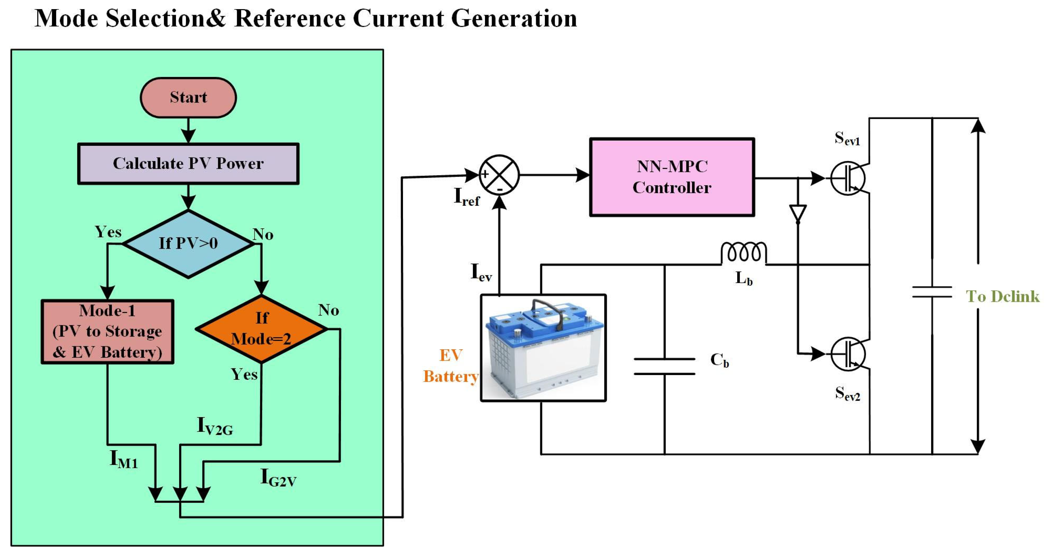
Figure 9. A decision-making flowchart that starts with a PV power availability calculation is shown on the left side. The system switches to Mode-1, where energy is transferred from the PV source to the EV battery and the storage system if the PV power exceeds zero. The system considers other operating modes if extra energy balancing is needed. Depending on energy demand and supply conditions, Modes 2 and 3 depict several situations in which electricity can be transferred between the EV battery and the grid, either in a V2G or G2V mode.
An NN-MPC controls the system’s control mechanism, adjusting the reference current Iref to ensure that the EV battery charges and discharges at its best. To produce the proper switching signals for power flow management, the NN-MPC controller processes the error between the real EV battery current Iev and the reference value. The power conversion system maintains the necessary voltage levels while ensuring steady energy delivery. The semiconductor switches dynamically manage the power flow from the EV battery to the DC link. In EV-integrated smart grids, this control approach improves bidirectional energy management, enabling effective PV-to-battery charging, V2G, and G2V operations. By anticipating system behavior and modifying control operations accordingly, NN-MPC enhances response time and accuracy. By intelligently controlling energy exchange based on current conditions, this configuration not only maximizes EV charging but also promotes grid stability.
4. Results and Discussion
This section evaluates the performance of the proposed control scheme across three operational modes, comparing it with conventional PI control to demonstrate its superior performance in managing bidirectional power flow. Each mode addresses a different energy management scenario commonly encountered in renewable energy systems with EV integration. The analysis begins with examining the NN-MPC training process and parameter selection, thus establishing the foundation for understanding the controller’s behavior. Subsequently, each operational mode is analyzed in detail, as follows:
Mode-1 (PV in full irradiance) demonstrates the system’s ability to efficiently distribute power from PV generation to storage and EV batteries.
Mode-2 (V2G) showcases the controller’s effectiveness in managing power flow from vehicles to the grid.
Mode-3 (G2V) evaluates the system’s performance when transferring power from the grid to vehicles. Throughout this section, particular attention is given to power quality, transient response, and overall system stability under varying conditions.
4.1. NN-MPC Training Details for the Proposed Scheme
Before examining the system’s operational modes, it is essential to understand the controller’s training process and parameter selection, as these directly influence its predictive capabilities and control performance.
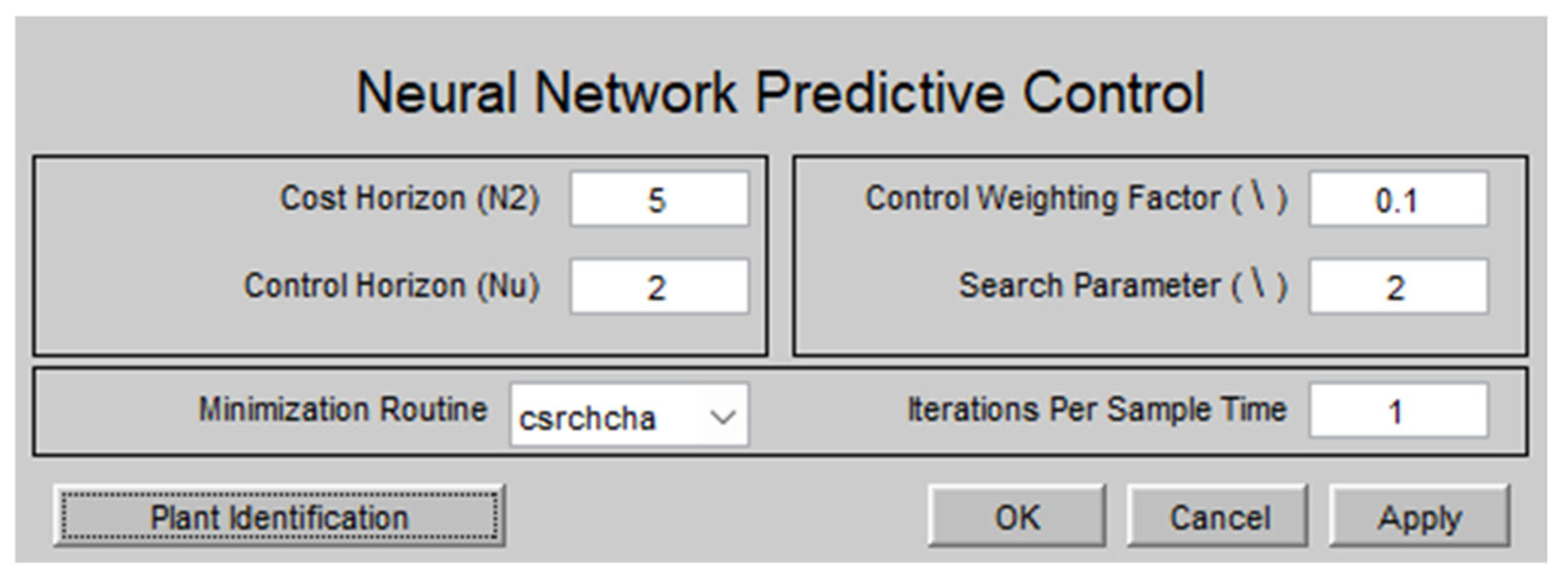
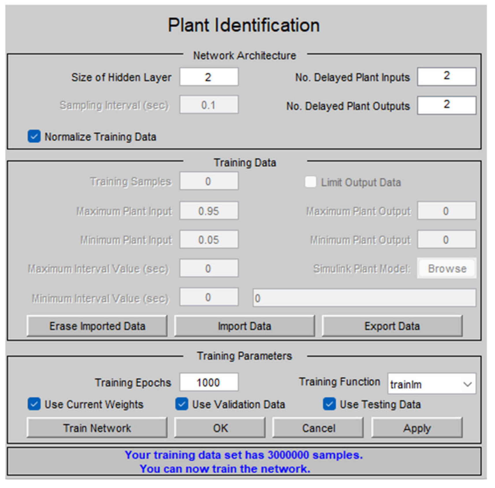
The NN-MPC controller was configured with carefully selected parameters to balance prediction accuracy with computational efficiency. As shown in
Figure 10, the key parameters include a cost horizon (N2) of 5, a control horizon (Nu) of 2, a control weighting factor (λ) of 0.1, and a search parameter of 2. These parameters were selected based on preliminary optimization studies to ensure robust performance across the system’s operational range. The cost horizon of 5 provides sufficient future visibility for effective prediction while maintaining computational tractability, while the control horizon of 2 allows for responsive yet stable control actions. The relatively low control weighting factor (0.1) prioritizes tracking performance over control effort minimization, which is appropriate for this application where precise power management is critical.
The NN model plant specifications, detailed in
Figure 11, were designed to capture the power conversion system’s complex dynamics. The model incorporates two hidden layers, providing sufficient complexity to model the nonlinear relationships between control inputs and system outputs while avoiding overfitting. The plant inputs include control signals for power converters, while outputs encompass critical system variables, such as battery state-of-charge, power flows, and DC link voltage.
The training process employed the Levenberg–Marquardt algorithm, which combines the stability of gradient descent with the speed of Newton’s method. This makes it particularly suitable for neural network training in control applications.
Figure 12 illustrates the trained NN model structure, showing the interconnections between layers and the information flow through the network.
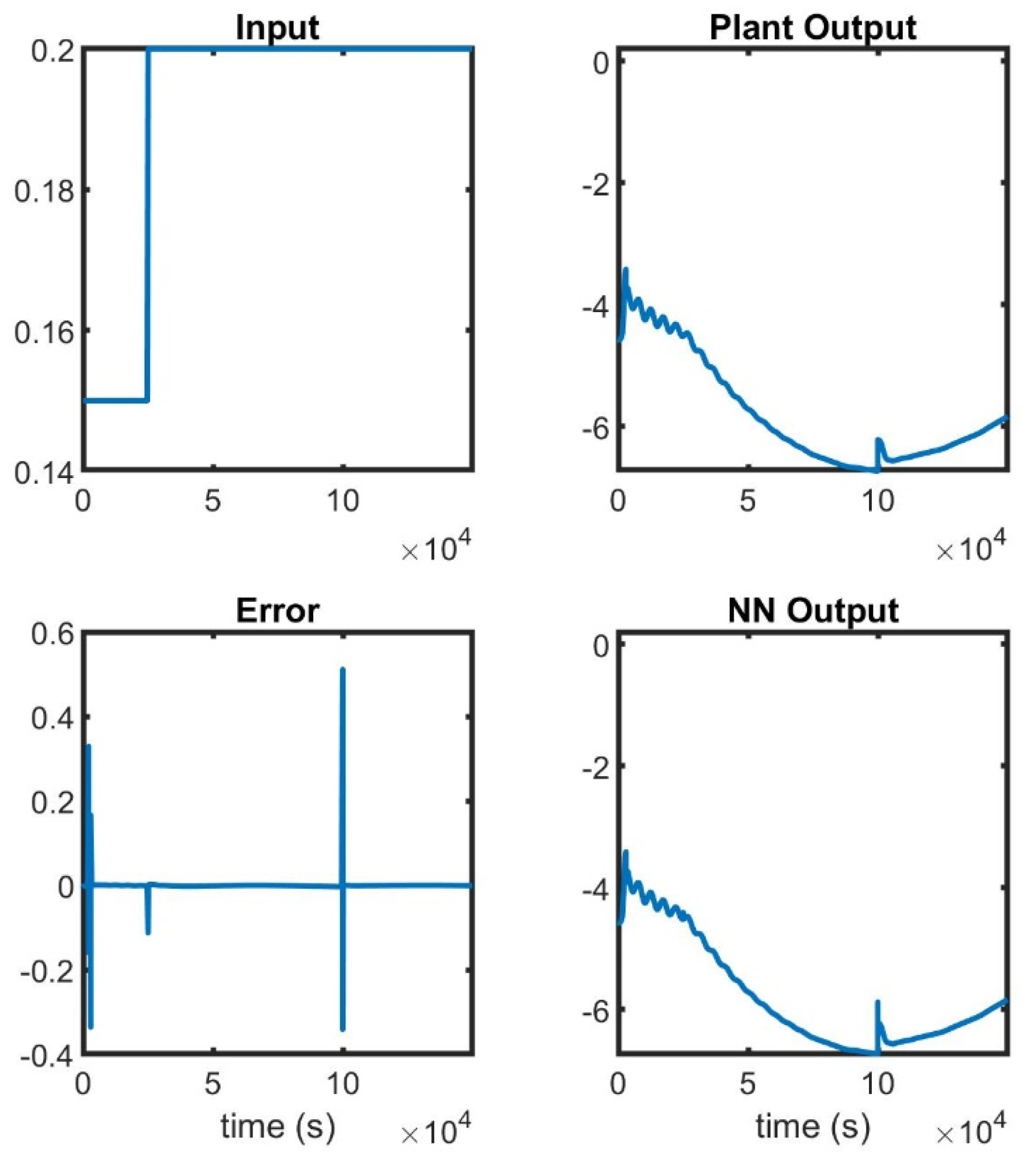
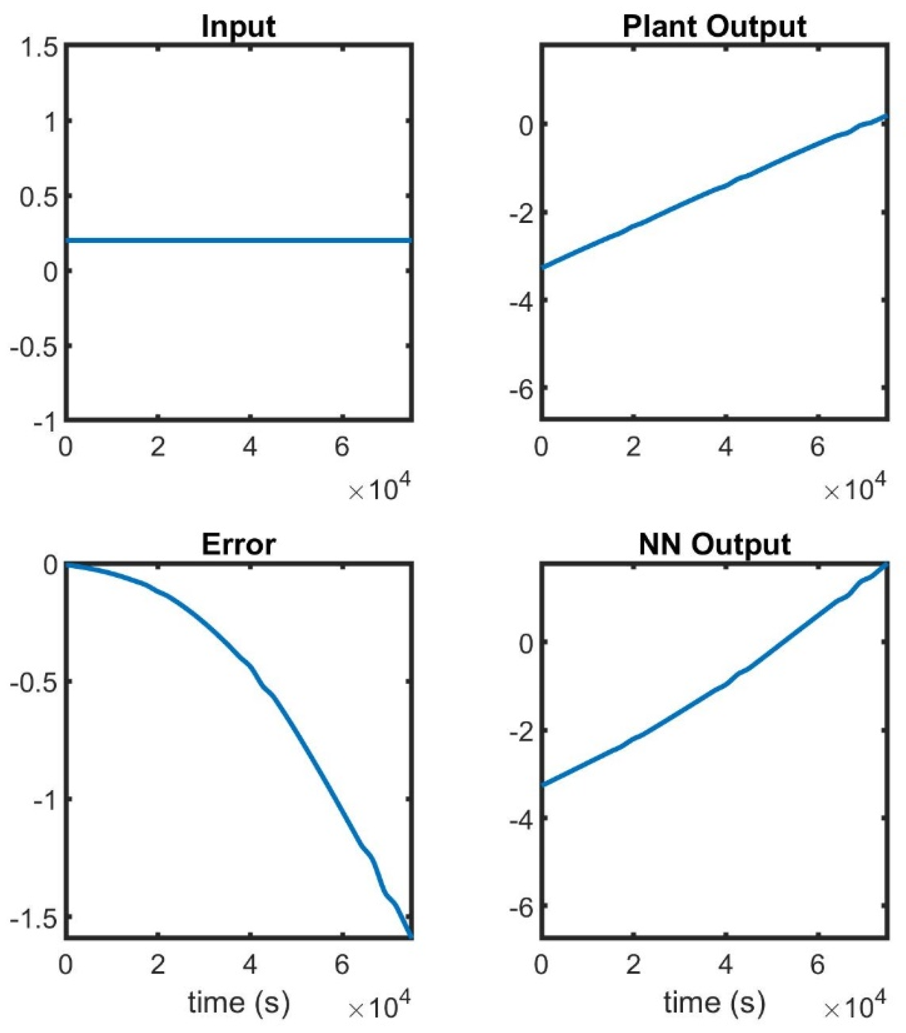
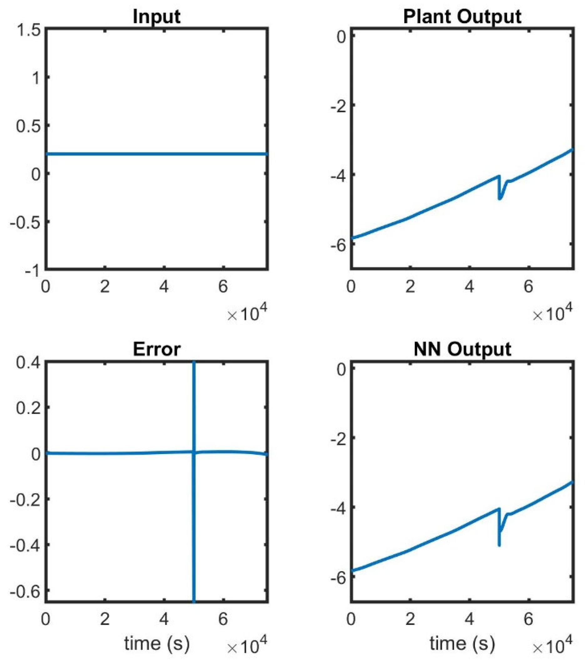
Figure 13,
Figure 14 and
Figure 15 present the input signals, plant outputs, prediction errors, and NN outputs during the training, testing, and validation phases, respectively. These figures demonstrate the NN’s ability to accurately predict system behavior across various operating conditions after training convergence, with minimal prediction error.
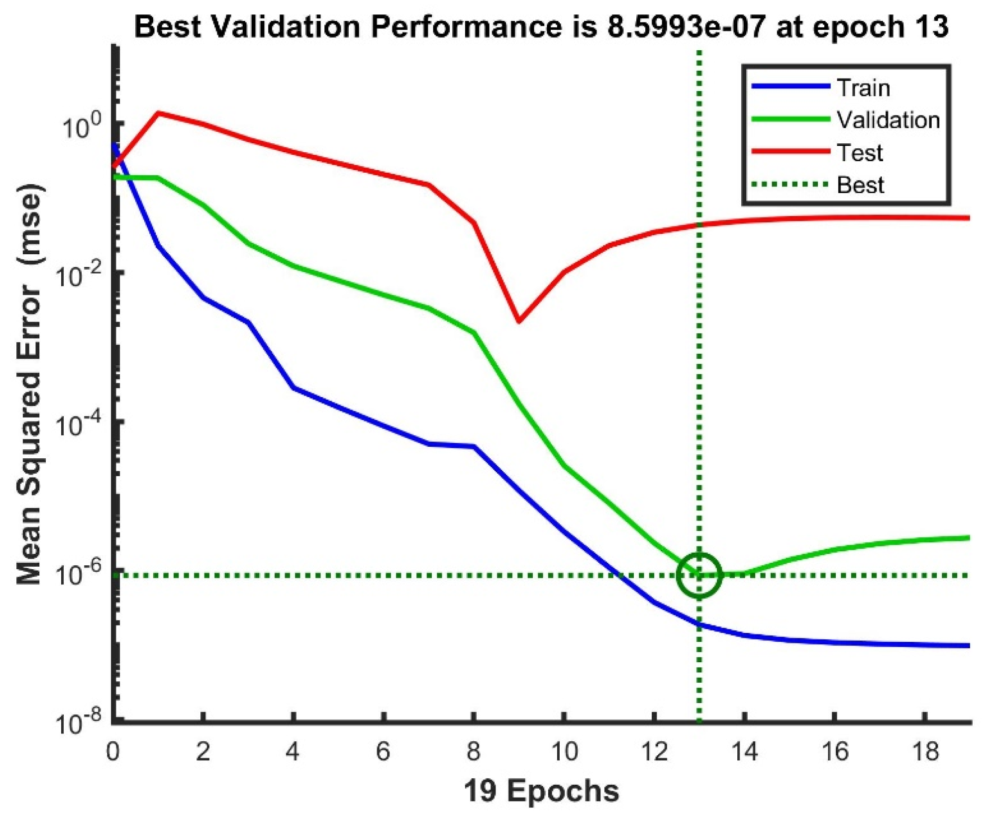
The mean squared error (MSE) was used as the primary performance metric during training, with its evolution over 19 epochs shown in
Figure 16. The training process exhibits a healthy learning curve, with the MSE decreasing rapidly in early epochs and then gradually stabilizing. The best validation performance occurred at epoch 13, achieving an MSE of 8.5993×10
−7, which indicates excellent prediction accuracy. The slight increase in validation and test errors beyond this point suggests the onset of overfitting, justifying the selection of the epoch-13 model for implementation.
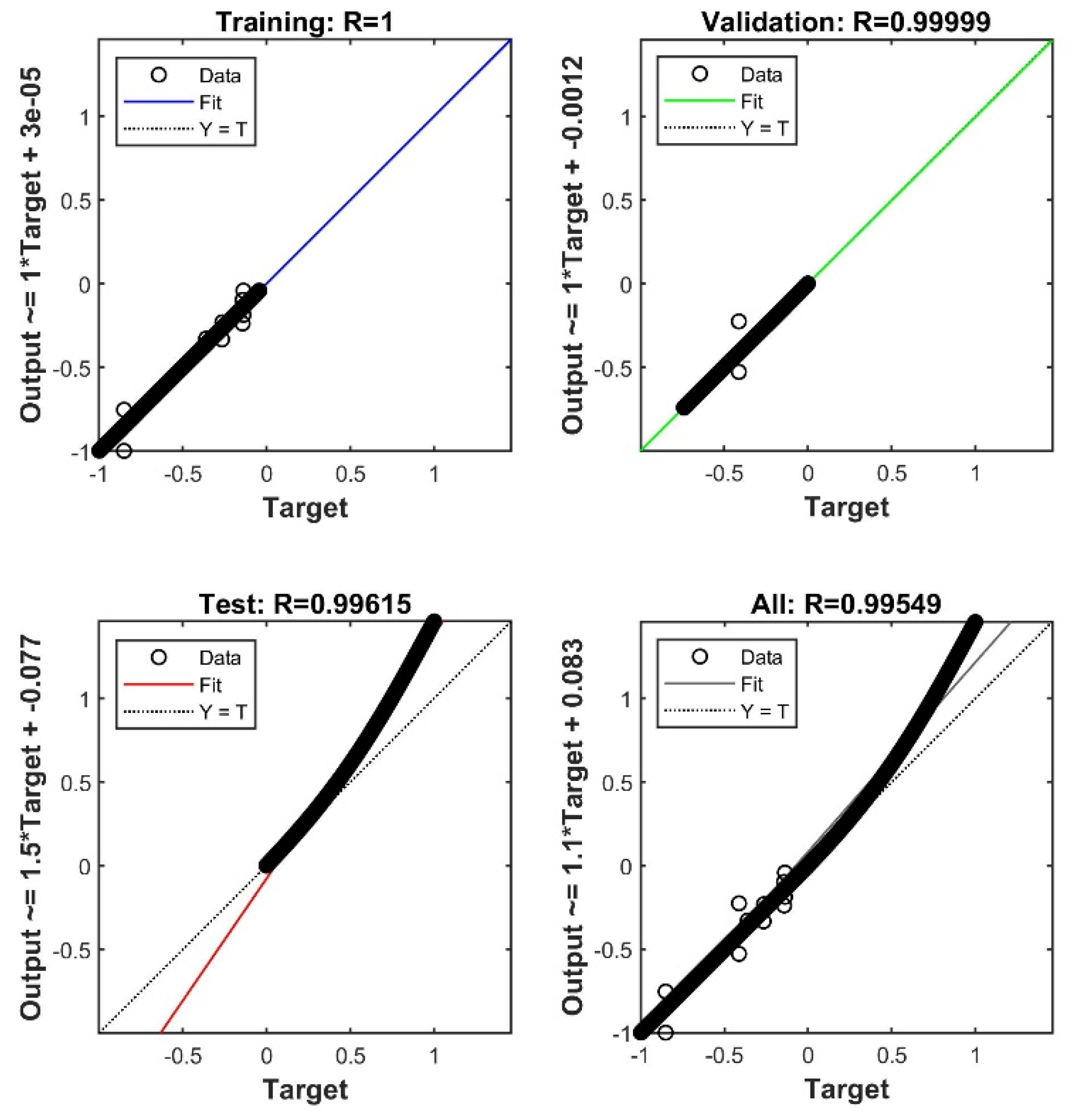
The regression plot in
Figure 17 further confirms the NN’s prediction quality, showing a strong correlation between targets and outputs across all datasets (training, validation, and testing). This comprehensive training approach ensures that the NN-MPC controller can effectively predict system behavior and optimize control actions across the various operational modes examined in subsequent sections.
After training and validating the NN model, it was integrated into the MPC framework to enable real-time prediction and control. The NN-MPC controller will now be tested in different operating modes to evaluate its performance in managing energy flow within the PV–battery–EV system. The following sections present the system’s behavior under each mode, and the results of NN-MPC are compared against those obtained with a conventional PI controller to highlight the improvements of the proposed approach.
4.2. Mode-1 (PV in Full Irradiance)
Mode-1 represents the system’s operation under optimal renewable generation conditions, with the PV array producing near its rated capacity at 1000 W/m
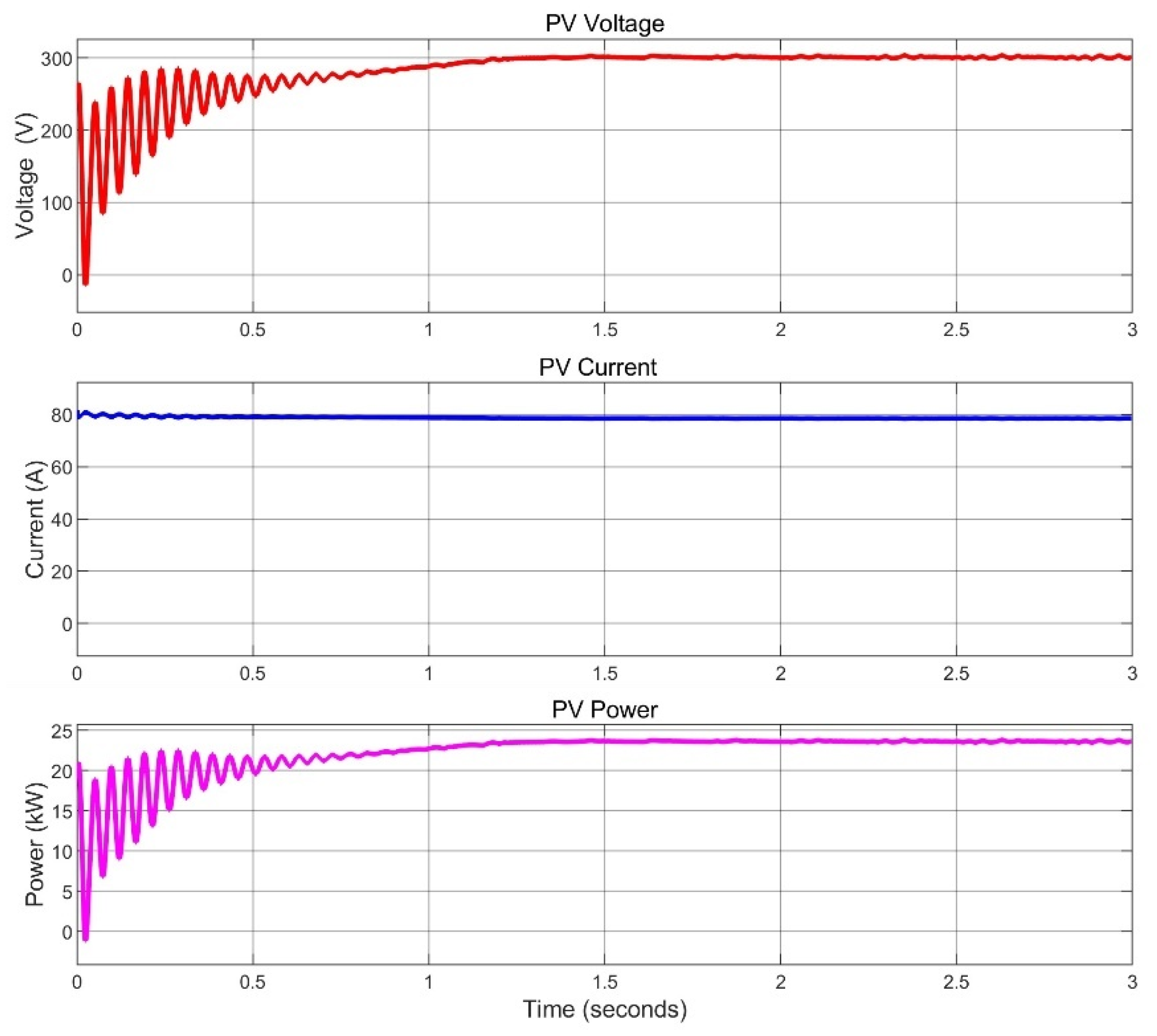
2. The implementation of P&O MPPT is essential in this mode, as it ensures maximum energy harvest despite variations in temperature and minor irradiance fluctuations. The measured power output of 23.63 kW from the 24.94 kW-rated PV array represents a 94.7% conversion efficiency. The power obtained is shared with the storage battery (SB) and EV battery for charging.
Figure 18 represents the PV parameters of Mode-1.
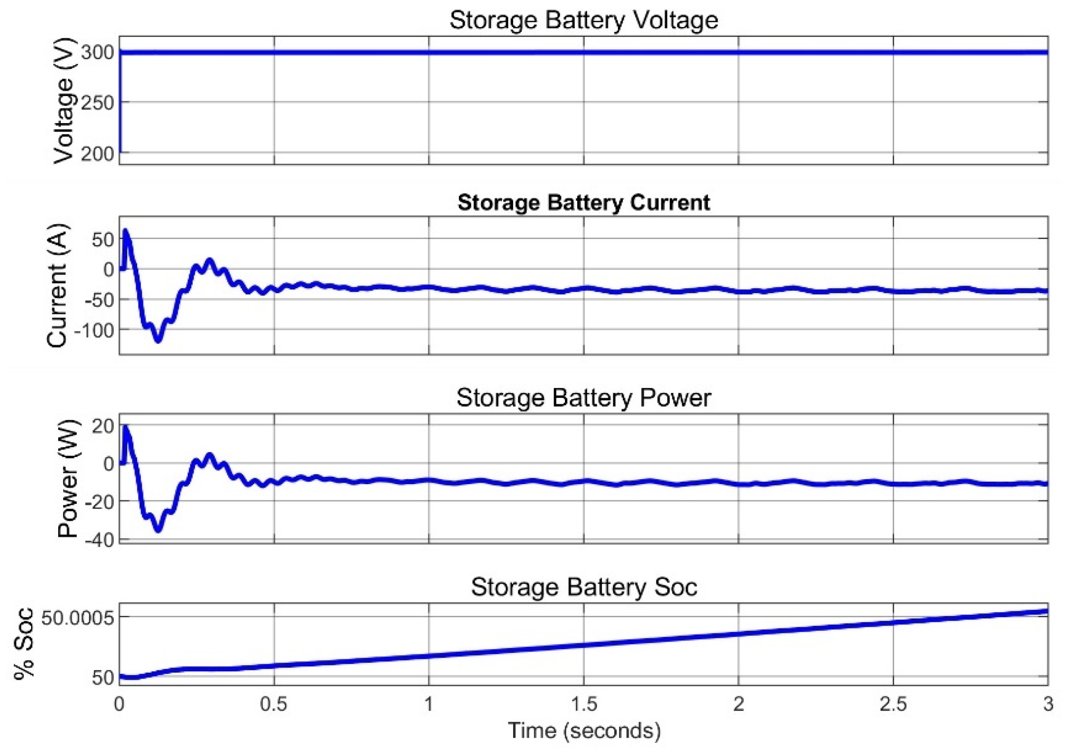
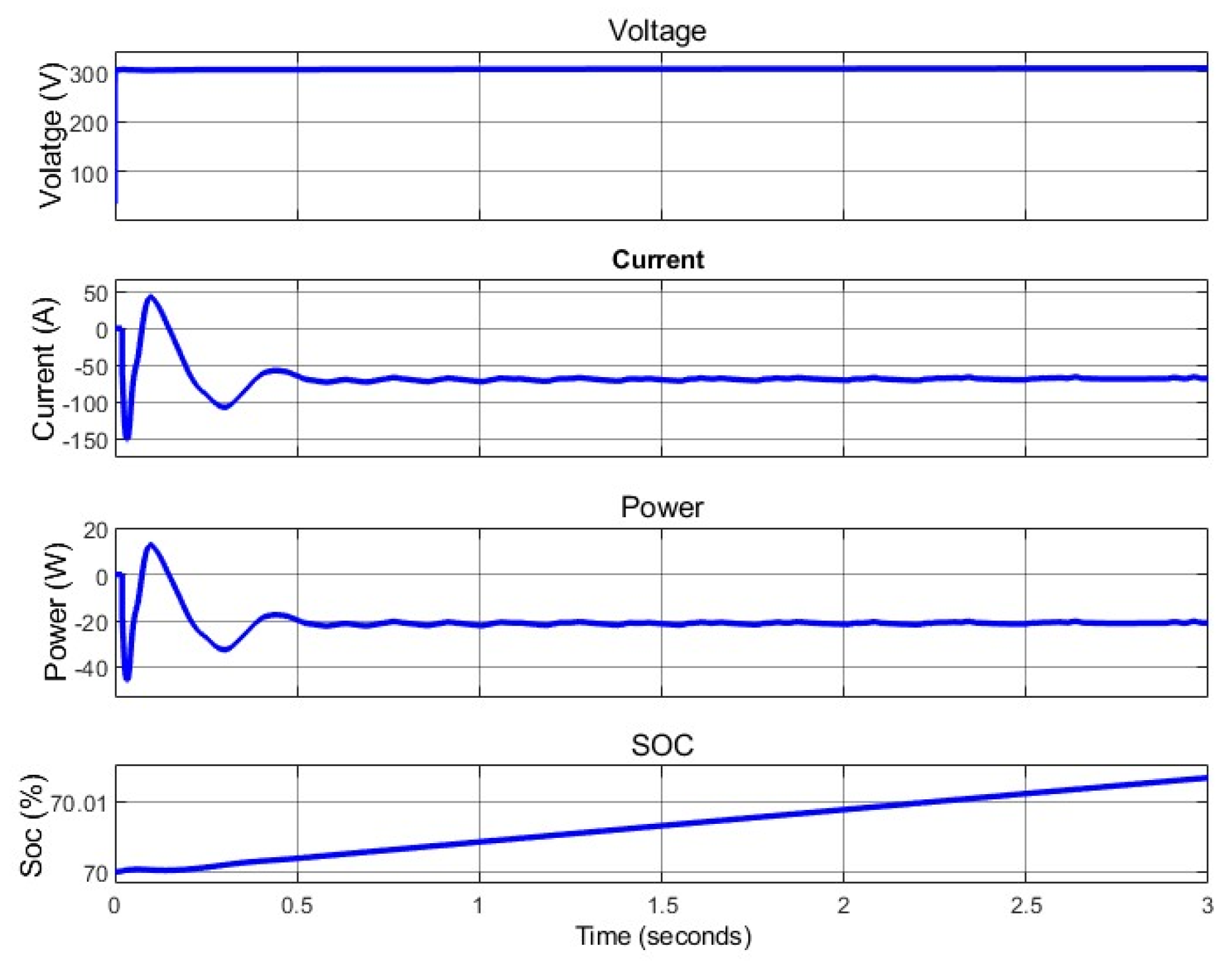
After visualizing the performance of PV operating at its maximum power in Mode-1, with a slight decrease due to conversion efficiency, the behavior of the storage battery (SB) operation is evaluated under this mode. To achieve this, the initial SOC of the storage battery is set to 50%, and the voltage, current, power, and SOC of the storage battery are measured and presented in
Figure 19. The results comply with the expected output, having a constant voltage of 300 V and a negative current and power, indicating that the battery is in a charging state and that the SOC is increasing over time.
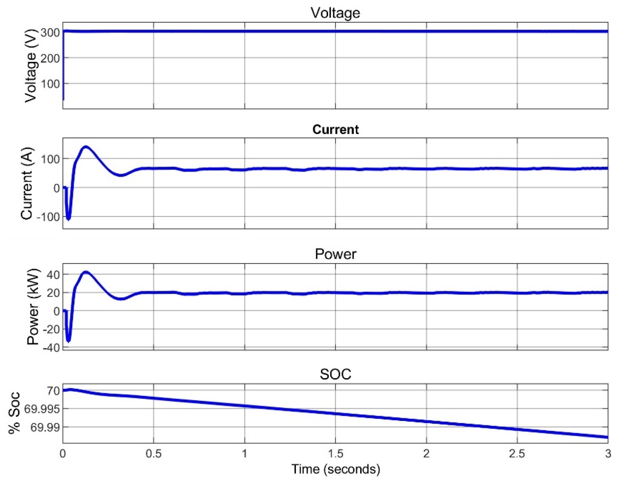
Similar to the storage battery, the same outputs are measured for the EV battery and given in
Figure 20, but with the initial SOC of the EV set to 70%. The results also show that the EV battery is charging under Mode-1.
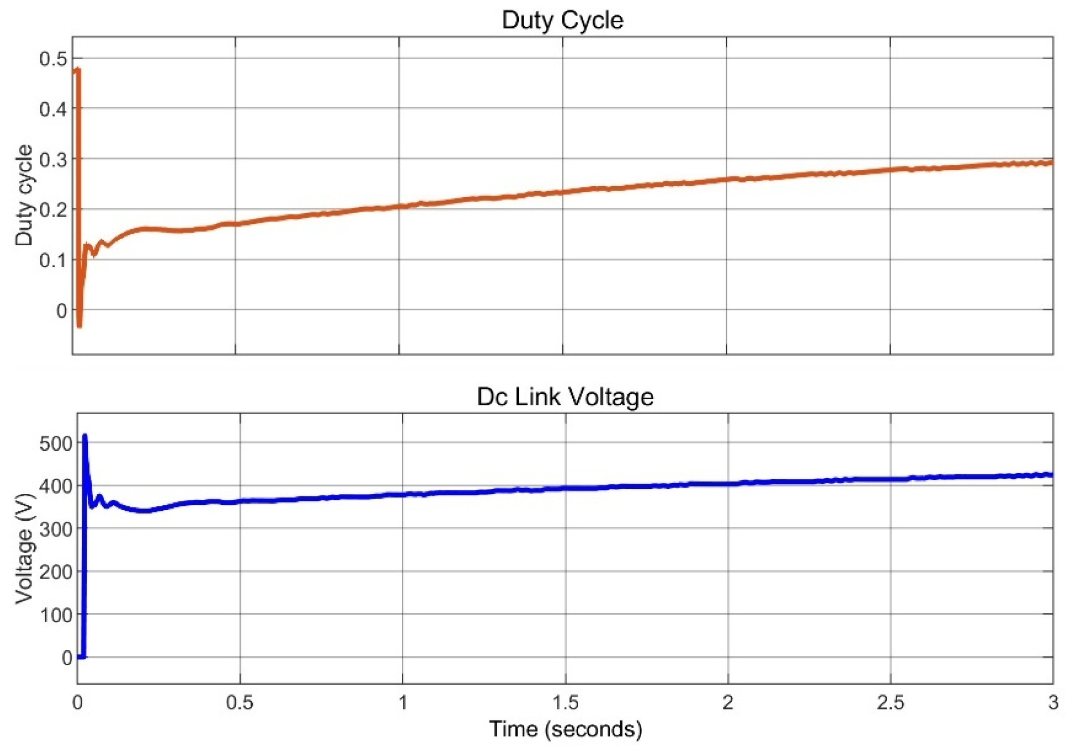
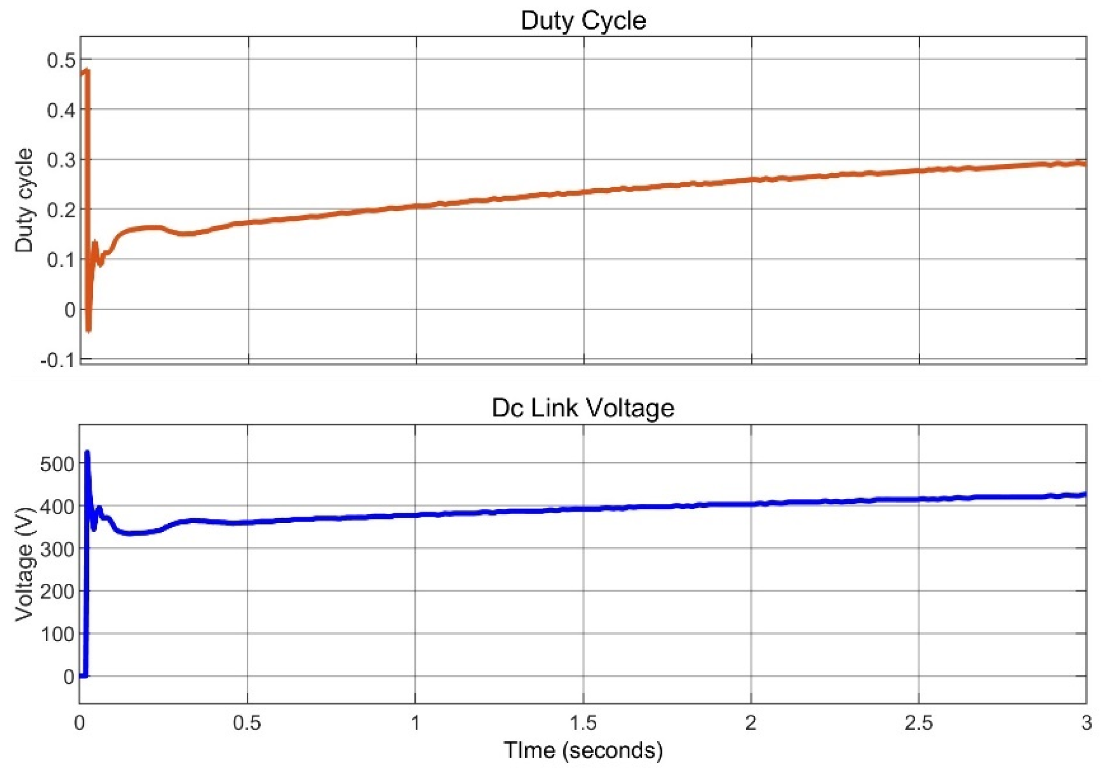
Figure 21 presents the duty ratio and the DC link voltage. The DC link voltage is maintained at 400 V.
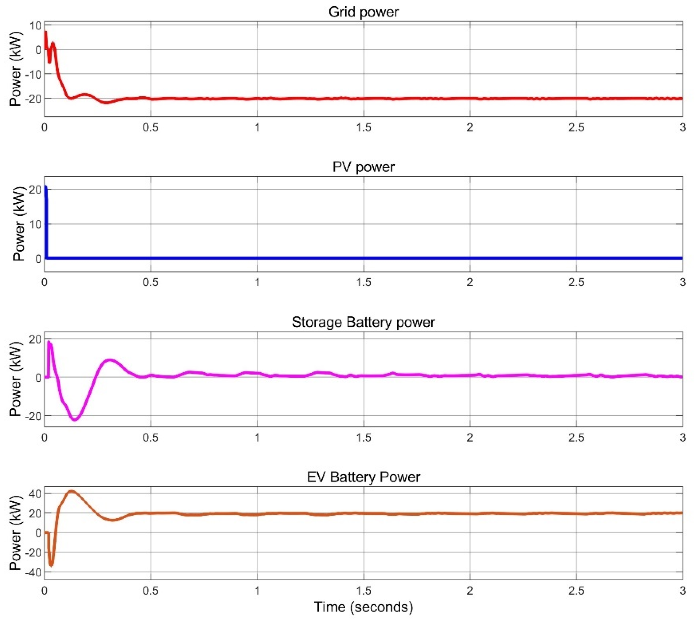
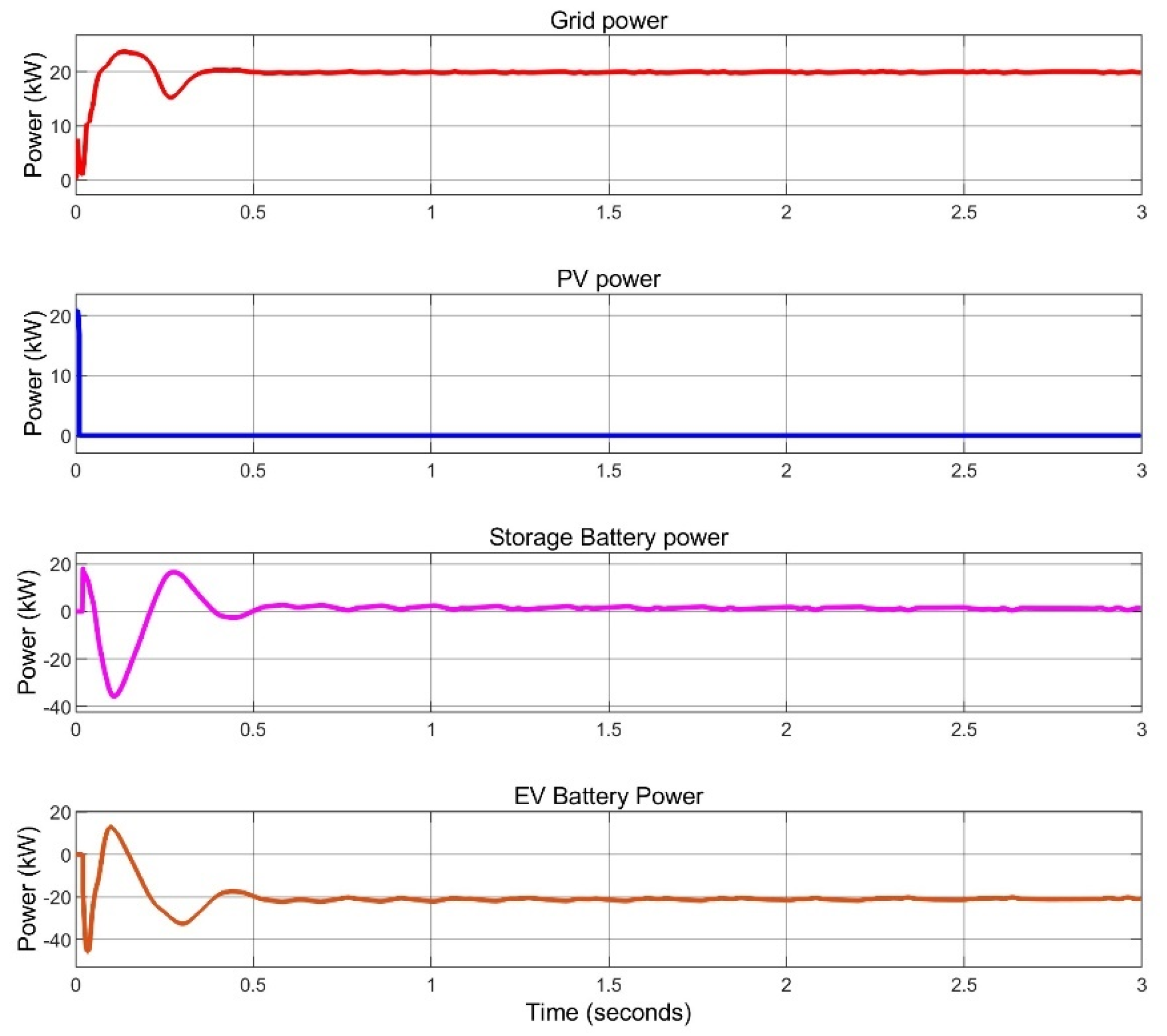
The power contributions from the grid, PV system, SB, and EV battery under Mode-1 operation are illustrated in
Figure 22. In this mode, the grid power remains zero while the PV operates at its maximum power point. The energy generated by the PV is utilized to simultaneously charge both the SB and the EV battery.
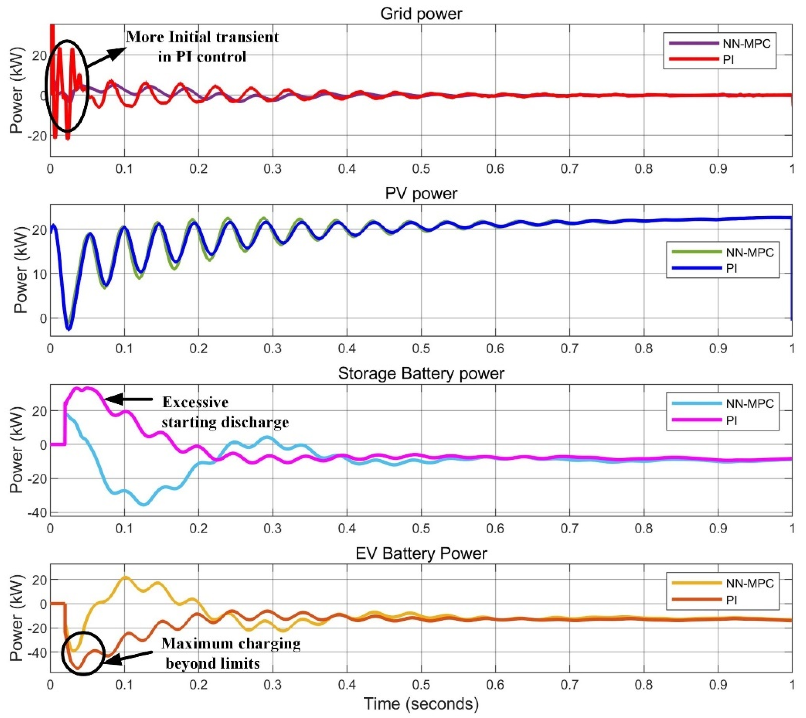
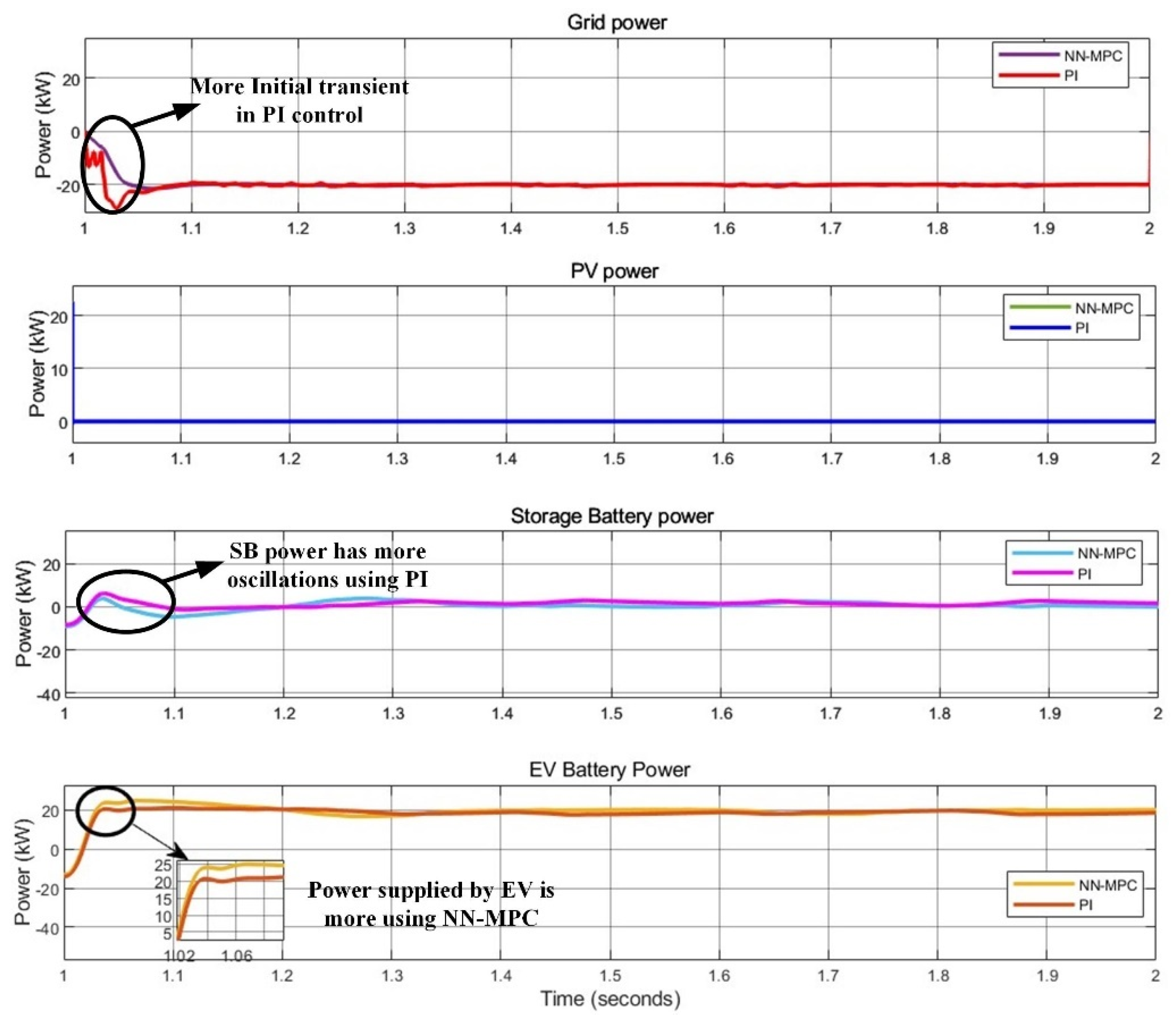
To evaluate the effectiveness of the proposed NN-MPC, a comparative analysis with the conventional PI controller under Mode-1 is presented in
Figure 23. Initially, the system controlled by the PI controller exhibits significant transients at the grid interface. Although the control strategy aims to draw power from the PV, the SB undergoes an initial discharge of approximately 25 kW, which can adversely impact its operational lifespan, considering that its maximum power capacity is limited to 40 kW. Under PI control, this initial discharge exceeds the permissible limit, surpassing 40 kW. In contrast, the EV battery remains within its maximum power boundaries. The NN-MPC, however, effectively mitigates these transients and maintains the SB discharge within safe operational limits. Therefore, the proposed NN-MPC demonstrates superior performance under Mode-1 conditions.
4.3. Mode-2 (V2G)
Mode-2 demonstrates the system’s capability to support grid operations by transferring power from electric vehicles to the grid when renewable generation is unavailable. This V2G functionality represents an increasingly important capability in modern power systems, where EVs can serve as distributed energy resources to support grid stability, provide peak shaving, or participate in ancillary service markets.
In this mode, when the PV power is zero, the mode is switched based on the requirement. Here, Mode-2 is activated as the grid needs power. Hence, the power is supplied from the V2G function. The EV battery parameters under Mode-2 are presented in
Figure 24. The power sent by the EV battery is 20.16 kW. Here, the SOC of the EV battery decreases from 70%. The grid receives power from the vehicle. The power received from the grid is 20.12 kW. The grid parameters under Mode-2 are illustrated in
Figure 25.
Figure 26 represents the duty cycle and DC link potential under Mode-2. Irrespective of the power flow from V2G, the DC link potential is kept constant at 400 V, enabling smooth power flow from V2G.
The power profiles of the grid, PV system, SB, and EV battery under Mode-2 are presented in
Figure 27. As previously discussed, the behavior of the EV battery was examined, where it delivers 20.16 kW to the grid. The grid receives 20.12 kW, while the PV contribution remains zero. A comparison between the proposed NN-MPC and the conventional PI controller under Mode-2 is illustrated in
Figure 28.
Initially, the grid suffers from excessive transients using PI control. The proposed NN-MPC provides smooth power transfer. In this mode, as the control is designed to receive power from vehicle to grid, using PI control, the power sent from the EV battery is around 17.86 kW, which is less than the NN-MPC control. Here, using PI, the SB also has some discharge, which affects the DC link voltage and makes the power flow complex. Hence, NN-MPC provides superior performance in Mode-2 by effectively transitioning power from an EV to the grid.
4.4. Mode-3 (G2V)
Mode-3 represents the G2V operation, where grid power is utilized to charge electric vehicles when renewable generation is unavailable. This functionality is essential for ensuring EV charging availability regardless of renewable resource conditions, making it a critical component of reliable EV charging infrastructure.
In this mode, when the PV power is zero, the mode is switched based on the requirement. Here, Mode-3 is activated as the EV battery needs power. Hence, the power is supplied from the G2V function. The EV battery parameters under Mode-3 are presented in
Figure 29. The power received by the EV battery is 20.05 kW, and the SOC of the EV battery rises from 70%, indicating the charging state. The power sent by the grid is 20.06 kW. The grid parameters under Mode-3 are illustrated in
Figure 30.
Figure 31 shows the duty cycle and DC link potential under Mode-3. The DC link potential remains at 400 V regardless of the power flow from the vehicle to the grid. This makes it possible for power to go smoothly from the V2G.
The power of the grid, PV, SB, and EV battery under Mode-3 are presented in
Figure 32. The grid sends 20.06 kW to the EV. The power received by the EV battery is 20.05 kW, and the PV power is nil. The comparison of the NN-MPC with conventional PI under Mode-3 is presented in
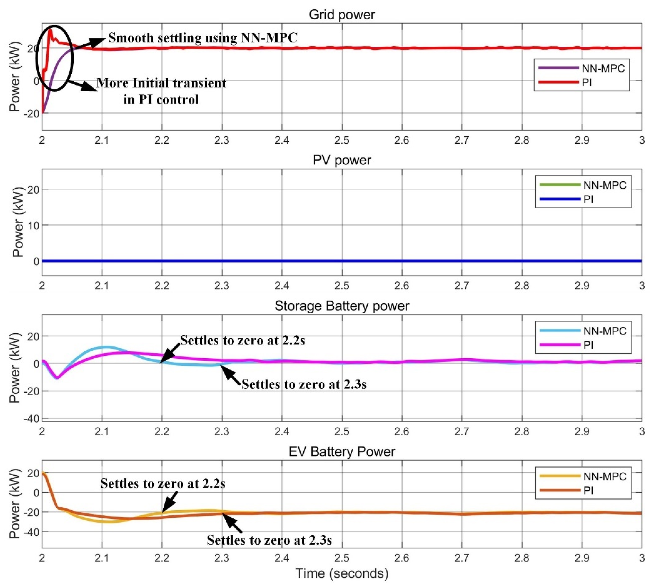
Figure 33. Initially, the grid suffers from excessive transients using PI control that affect the connected loads. The proposed NN-MPC provides smooth power transfer. In this mode, as the control is designed to receive power from the grid to the vehicle, using PI control, the settling time for the SB and EV power is longer, and the power received by the EV battery is around 20.05 kW. Here, the NN-MPC control offers less settling time than PI and provides smooth grid power without any transients.
4.5. Comparison of All Modes with PI and NN-MPC Control
The comparison of all the modes at different time intervals is represented in
Figure 34.
Table 3 compares the power flow among different components under the three modes using PI control and NN-MPC. The results illustrate the superior performance of NN-MPC in managing power flow and ensuring efficient energy utilization compared to conventional PI control. The sign convention in
Table 3 shows the direction of power flow; positive power values indicate discharging, while negative power values indicate charging.
Under Mode-1, where the PV operates at full irradiance (1000 W/m2), the total power generated is 23.56 kW, which is equally captured by both PI and NN-MPC controllers. However, the power distribution among the storage and EV batteries differs. Under NN-MPC, the storage battery receives 11.43 kW, slightly higher than 11.21 kW with PI, ensuring better power allocation. Similarly, the EV battery receives 12.13 kW under NN-MPC, compared to 11.24 kW with PI. This improved distribution highlights the controller’s enhanced capability to manage internal energy coordination, ensuring optimal charging.
Under Mode-2, when PV power is unavailable, the EV battery supplies power to the grid. A key difference emerges when the storage battery under PI control experiences an uncontrolled discharge of 2.12 kW, an unplanned and inefficient response that signals poor coordination between the storage and EV batteries. In contrast, NN-MPC completely avoids this issue. The EV battery, controlled by NN-MPC, delivers a higher 20.16 kW to the grid, compared to just 17.86 kW under PI, indicating that NN-MPC enhances power injection into the grid by 12.9%. This allows the EV to ensure grid support, meeting its demand while preserving the storage battery’s health. Furthermore, the grid receives slightly more power under NN-MPC, i.e., 20.12 kW versus 19.98 kW with PI, while ensuring better power stability and fewer transients. This clearly highlights NN-MPC’s advantage in maximizing EV participation and eliminating unnecessary stress on the storage reserves.
Under Mode-3, where the EV battery is charged from the grid due to the absence of PV generation, the power drawn from the grid is 20.06 kW for both PI and NN-MPC, ensuring stable operation. However, the EV battery charging performance improves with NN-MPC, as it receives 20.05 kW, compared to 20.03 kW under PI, pointing to lower system losses and tighter control during the charging process, reflecting NN-MPC’s ability to regulate power transfer efficiently while minimizing energy losses.
NN-MPC outperforms PI control in all modes by ensuring higher power transfer efficacy, reducing unwanted storage battery discharge, and maintaining grid voltage stability.
Analyzing the system performance across all three operational modes reveals several important insights about the proposed NN-MPC approach and its advantages over conventional control methods.
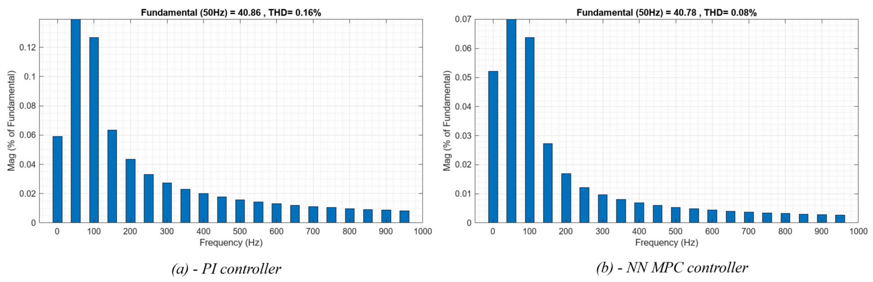
First, the NN-MPC demonstrates consistent superiority in transient response characteristics across all modes. The controller achieves settling times that are 38–40% faster than the PI control, with significantly reduced overshoot and oscillatory behavior. This improved transient performance is particularly valuable in renewable energy systems with EV integration, where changing environmental conditions and user requirements necessitate frequent transitions between operational modes. The power quality metrics show improvement with NN-MPC across all modes. The total harmonic distortion (THD) of the grid current shows a slight decrease, from 0.16% with PI control to just 0.08% with NN-MPC. This reduction contributes to smoother current waveforms and more stable grid interactions, which is important as distributed energy resources and EVs comprise a larger portion of the grid.
Figure 35 shows fast Fourier transform (FFT) analyses for both controllers to visualize the harmonic content in each case.
The NN-MPC demonstrates a superior ability to maintain system operation within safe limits across all modes. Unlike the PI controller, which allows power flows to exceed component ratings during transients, the NN-MPC consistently respects system constraints while still achieving optimal performance. This constraint-handling capability is a fundamental advantage of the MPC approach, enhanced by the neural network’s ability to accurately predict system behavior under various conditions. The efficiency of power conversion shows consistent improvement with NN-MPC across all modes. The controller achieves 2–5% higher efficiency compared to PI control, which translates to significant energy savings over the system’s operational lifetime. This efficiency improvement stems from the controller’s ability to optimize multiple objectives simultaneously, finding operating points that balance power transfer, losses, and component stress.
Finally, the NN-MPC demonstrates remarkable adaptability across different operational scenarios without requiring mode-specific tuning or parameter adjustments. This adaptability stems from the neural network’s ability to learn complex system dynamics and the MPC framework’s inherent flexibility in handling changing objectives and constraints. This “configure once, operate anywhere” capability represents a significant practical advantage for implementation in real-world systems, where manual retuning for different operational conditions would be impractical.
Table 4 summarizes the key system-level improvements of the NN-MPC controller over the PI controller, highlighting performance gains across various operational areas.
The superior performance of the NN-MPC approach across all operational modes has significant implications for the broader fields of renewable energy integration and EV charging infrastructure development. For renewable energy integration, the controller’s ability to efficiently manage power flows between multiple sources and storage elements addresses one of the fundamental challenges of high renewable penetration, namely the mismatch between generation and demand profiles. By optimizing the utilization of available storage capacity (both stationary and vehicle batteries) and maintaining high conversion efficiency, the system maximizes the effective utilization of renewable generation, reducing curtailment and increasing the economic viability of renewable installations.
For EV charging infrastructure, the bidirectional power flow capability with high efficiency and power quality opens new possibilities for vehicle–grid integration. The system’s ability to seamlessly transition between charging and discharging modes enables EVs to participate in grid services markets, potentially generating revenue for vehicle owners while supporting grid operations. The controlled charging and discharging processes also address concerns about battery degradation from V2G participation, potentially increasing the adoption of bidirectional charging capabilities.
From a grid operation perspective, the fast transient response and excellent power quality demonstrated by the NN-MPC approach help mitigate concerns about the impact of high EV penetration on distribution networks. By minimizing harmonic distortion and controlling ramp rates during mode transitions, the system reduces the potential for negative interactions with grid protection systems and other connected equipment.
The integration of advanced control strategies, like NN-MPC, with renewable energy systems and EV charging infrastructure represents an important step toward the realization of smart grid concepts, where distributed energy resources and flexible loads work in concert to enhance overall system efficiency, reliability, and sustainability.
5. Conclusions
This work presented an efficient EMS for an EV charging station integrating PV generation, battery storage, and bidirectional V2G and G2V power transfer using NN-MPC. The study demonstrated how NN-based forecasting, when combined with model predictive control, can improve real-time energy coordination under dynamic conditions. Three operating modes were used to assess the proposed NN-MPC technique against the traditional PI control. Effective power sharing between the storage and EV batteries was ensured by NN-MPC’s greater power extraction of 23.63 kW in Mode-1 when the PV works at full irradiance (1000 W/m2), as opposed to 23.45 kW with PI. Smoother power transitions and less needless storage battery discharge were ensured by NN-MPC, which transmitted 20.16 kW in Mode-2 (V2G Mode) when the EV battery discharged electricity to the grid. This represents 12.9% more than the 17.86 kW attained with PI. When the EV battery was charged from the grid in Mode-3, NN-MPC efficiently transmitted 20.05 kW instead of 19.67 kW under PI, preserving steady grid interaction. Across all modes, NN-MPC demonstrated superior dynamic response, reduced transients, and improved energy utilization, making it a viable solution for enhancing the performance of modern EV charging stations with grid integration.
While NN-MPC offers superior performance, it also has some limitations that must be addressed in future work. These include the need for significant computational resources, sensitivity to the neural network model’s accuracy, and the assumption of ideal communication and measurement conditions during operation. Future versions should explore model simplification and hardware acceleration for real-time embedded implementations. The proposed scheme should explore integration with other sources, such as wind or hydrogen fuel cells, test the scalability of the NN-MPC controller in larger grid models, and implement real-time experiments to validate practical feasibility. Future work will investigate hybrid RESs, including hydrogen fuel cells and wind, to improve system dependability and lessen reliance on the grid. Power flow may be further optimized, and system flexibility under changing load and grid circumstances may be enhanced by using sophisticated AI-based controllers, such as deep learning-based prediction models or reinforcement learning approaches. Hardware-in-the-loop testing and real-time implementation will be essential to validate the practical feasibility of NN-MPC for real-world EV charging infrastructure. Furthermore, integrating demand response strategies and smart grid capabilities will enable dynamic pricing mechanisms, vehicle-to-building (V2B) services, and optimal grid participation in V2G applications.


