Abstract
Wide-Area Power System Stabilizers (WAPSSs) are damping controllers used in power systems that employ data from Phasor Measurement Units (PMUs). WAPSSs are capable of providing high damping rates for the low-frequency oscillation modes, especially the inter-area modes. Oscillation modes can destabilize power systems if they are not correctly identified and adequately damped. However, WAPSS communication channels may be subject to failures or cyber-attacks that affect their proper operation and may even cause system instability. This research proposes a method based on an optimization model for the design of a WAPSS robust to multiple permanent communication failures. The results of applications of the proposed method in the IEEE 68-bus system show the ability of the WAPSS design to be robust to a possible number of permanent communication failures. Above this value, the combinations of failures and processing time are high and they make it difficult to obtain high damping rates for the closed-loop control system. The application and comparison of different optimization techniques are valid and showed a superior performance of the Grey Wolf Optimizer in solving the optimization problem.
1. Introduction
Power systems have become fundamental to the development of society and are constantly expanding. Generating, transmitting and distributing electricity continuously, without interruptions, with quality levels, without losses, without environmental damage and at the lowest economic cost are the main objectives of operating power systems. However, different types of contingencies and disturbances can occur and compromise the proper and desired operation of power systems [1,2,3,4].
Small disturbances and contingencies can cause the emergence of low-frequency oscillation modes associated with the electromechanical variables of the power system [5]. These oscillation modes can be called local if they are in the frequency range from 0.8 to 2.0 Hz or they can be called inter-area if they are in the frequency range from 0.1 to 0.8 Hz. If these oscillation modes have low damping rates, oscillations may arise in the dynamic variables of the system and, in the worst case, may cause a blackout in power systems [5].
Over the decades, different control strategies have been developed with the purpose of improving the damping rates of low-frequency oscillation modes in the field of small-signal stability studies [5]. The Power System Stabilizer (PSS) providing a control signal for the Automatic Voltage Regulator (AVR) in the excitation loop of synchronous generators proved to be effective in damping the oscillation modes, mainly the local modes [5]. Design techniques for PSSs were proposed by the scientific community and they proved the effectiveness of PSSs in guaranteeing stability and good dynamic performance of power systems [6,7,8].
PSSs are effective in improving the damping rates of local modes, but have limited effect in improving the damping rates of inter-area modes. The expansion of power systems in terms of increased generation and increased load causes the increase in inter-area oscillation modes with low damping ratios that can also be harmful in the operation of power systems. As PSSs are local and lack system-wide observability, they have difficulty acting on inter-area modes [5].
The development of Wide-Area Measurement Systems (WAMSs) provided great advances in improving the observability of power systems. WAMSs are equipped with Phasor Measurement Units (PMUs) installed in different buses of the system that measure three-phase signals of voltage in the buses and currents in the branches with high sampling rates and synchronization in time because they use Global Positioning System (GPS) [9]. Synchronized real-time data from power systems aroused the interest of the scientific community in developing different strategies to improve monitoring [10,11,12,13,14], control [15,16,17,18] and protection [19,20,21] of power systems.
In the field of power system control, Wide-Area Damping Controllers (WADCs) have been developed and consist of using data from remote system PMUs and providing additional control signals to improve the damping rates of the system’s oscillation modes. As the use of remote data allows a greater observability of the system, the WADC is effective in improving the inter-area modes of the system. The first control design proposals adopted a two-level control structure where the first level is PSS design and the second level is WADC design [22]. Thus, the operation of both PSSs and WADC improves both local and inter-area modes of power systems.
In recent years, different WADC designs have been proposed using different techniques such as linear matrix inequalities [23], linear quadratic regulators [24], metaheuristics [25], deep neural networks [26] and different controllers such as WAPSSs and FACTS. Unlike the traditional design of PSSs, the design of a WADC involves additional challenges: (i) determining the appropriate choice of remote signals for the WADC from a strategy, (ii) determining the choice of a model to represent and/or mitigate time delays in the transmission of data from PMUs from remote locations, and (iii) assessing strategies to deal with communication failures and cyber-attacks on communication channels or protocols.
With regard to the choice of remote signals, methods based on residuals, geometric measures [27] and metaheuristic [28] were proposed and the results were effective in the purpose of WADC to improve the dynamic performance of the system. The next challenge in WADC design is the handling of time delays in data transmission. The authors of [29] evaluated and concluded that time delays can worsen the dynamic performance of the system if they are not correctly treated in the design. Different proposals have been introduced over the years. The authors of [30] consider a fixed and maximum time delay in data transmission represented by Padé approximations. The authors of [31] proposed time delay compensators to act on the WADC in real time and mitigate possible problems. The authors of [32] sought to determine allowable time delay ranges that do not affect the control objective. The authors used artificial neural networks to estimate the time delay and use this estimation in the control design. Research carried out so far has been effective and contributes to the better performance of WADC in power systems.
Communication failures and cyber attacks are recent concerns in the scientific community in research dependent on PMU data. A recent cyber-attack in Ukraine caused a blackout in the country’s power system [33]. In the field of control design research, the authors of [34] showed that a denial-of-service attack can present a data sequence that interferes with PMU data communication channels and causes the loss of this communication channel. Thus, cyber-attacks or communication failures can affect the proper operation of a WADC and even destabilize the entire system. Some recent works have tried to solve some of these problems. The authors of [35,36,37,38,39] proposed methods to ensure that the designed WADC is robust to one permanent loss of communication. The authors of [40] propose a WADC design method that guarantees robustness to False Data Injection Attacks. The authors deal with transient data loss from PMUs. The authors of [41] proposed an approach to deal with Deceptions Attacks. The results are promising but challenges still persist and the work is still recent.
This article proposes a WADC design method capable of improving the damping rates of the system’s low-frequency oscillation modes and tolerating multiple WADC channel communication failures. The WADC will be of the WAPSS type where the representations of the gain of each transfer function of the controller will be the key for the design of WAPSSs which are robust to multiple communication losses. The closed-loop control system is described in Figure 1. The proposed method consists of solving an optimization model subject to constraints. Different metaheuristics such as Particle Swarm Optimization (PSO), Crow Search Algorithm (CSA) and Grey Wolf Optimizer (GWO) are applied and evaluated to solve the optimization problem. Case studies are performed and discussed for IEEE 68-bus. Furthermore, modal analysis and dynamic simulations are applied and evaluated. Thus, the contributions of this research can be summarized as follows:
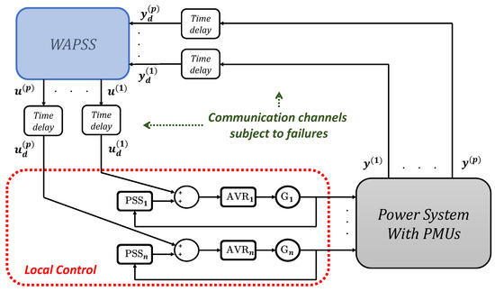
Figure 1.
Two-level control structure composed of PSSs and the WAPSS.
- A new optimization model is proposed for the design of a damping controller of the WAPSS type whose mathematical formulation is composed by a gain and a time constant.
- A mathematical formulation is included in the optimization model through the evaluation of the control structure gains to allow the WAPSS type controller to be robust to multiple permanent communication losses.
- The WAPSS project involves solving an optimization model and thus different metaheuristics are applied, evaluated and discussed in order to evaluate the feasibility of finding a WAPSS controller capable of tolerating multiple permanent communication losses.
The remainder of this article is organized as follows. Modeling of power systems, time delays and control structure are described in Section 2. The proposed WAPSS design method is presented in Section 3. Case studies are evaluated and discussed in Section 4. The conclusions of this research are presented in Section 5.
2. Modeling
2.1. Power System Model
Power systems are dynamic systems composed of synchronous and asynchronous generators, AVRs, PSSs, buses, transmission lines, transformers and other equipment whose operating principles can be represented by non-linear differential-algebraic equations. In control designs, these equations can be linearized around each operating point and represented by state-space Equations (1) and (2), where , and represent the vectors of state, output and input variables. Furthermore, matrices , and are called state, input and output matrices and .
In control projects whose objective is to improve damping rates, a modal analysis is performed on the state matrix to identify the eigenvalues with lower damping rates and which the controllers need to improve.
2.2. Time Delay Model
As mentioned, time delays are inherent in PMU data dependent devices. In this research, the second-order Padé approximation was applied [22] and can be modeled by the transfer function (3), where T is the time delay. In this research, time delays must be considered at the input and output of the WAPSS type controller.
As the power system and time delay models are known, it is possible to aggregate them and obtain a single model in state-space given by Equations (6) and (7), where each of the matrices , and are obtained from Equations (8)–(10), respectively.
Thus, the modal analysis can be conducted on the state matrix to evaluate eigenvalues and choose the signals that will compose the WAPSS.
2.3. Wide-Area Power System Stabilizer Model
The damping controller of this research will use data from velocity signals estimated by data from PMUs. The objective is to improve the damping rates of the oscillation modes, especially the inter-area oscillation modes that require a higher observability of the system. The damping controller used in this research has multiple inputs and outputs and thus can be represented by a matrix of transfer functions given by Equation (11), where each matrix element is given by Equation (12), where is the gain and , , and are time constants.
From the transfer function matrix and using Jordan’s observable canonical form, it is possible to obtain the state-space equations defined by (13) and (14) that will be useful in the formulation of the closed-loop control system.
PMUs measure voltage and current in electrical systems and the WAPSS damping controller applied in this research uses speed signals as input. There are methods in the literature that estimate velocity signals from PMU data [42,43]. For these estimates to be effective, it is necessary that PMUs be installed as close to the generators as possible, so it was considered in this research that there is a PMU on each bus where a generator is located.
2.4. Closed-Loop Control System Model
In control design, the design of the WAPSS is as important as its behavior in the closed-loop control system. Different indices can be evaluated in the control system to evaluate if the performance criteria are satisfactory and sufficient for an adequate operation of the WAPSS.
The closed-loop control system comprises the WAPSS-type controller to be designed (11) and the open-loop system (6) and (7). In control designs, it is usual to assess whether the closed-loop control system meets the desired performance requirements with the WAPSS candidate. In this research, the desired performance requirement is to ensure that all eigenvalues of the closed-loop control system present damping rates greater than 5%, a satisfactory index value in small-signal stability studies [44].
Thus, if we define the vector of the closed-loop system as (15), the system of equations in state space is given by (16), where the closed-loop matrix is given by (17). From matrix it is possible to evaluate the damping rates of all eigenvalues of the closed-loop control system through the Formula (18).
Index (18) will be essential for the WAPSS controller design and will be used in the optimization model to achieve a desired performance criterion for the system.
2.5. Multiple Permanent Communication Failure Problem
In control projects where there is no risk of communication failures between the WAPSS communication channels, one can design the WAPSS and evaluate the closed-loop control system defined by (16). However, when permanent communication failures occur, the control system may not operate as desired. Consider the WAPSS control action defined by (19), where are the measured speed signals for the p generators of the system and that are the WAPSS inputs and are the control signals supplied by the WAPSS to the p comparators of the automatic voltage regulators. When the i-th WAPSS input channel is lost , the i-th WAPSS column has no effect under the control action, and when the j-th WAPSS output channel is lost , the j-th WAPSS row has no effect under the control action. Thus, the permanent loss of a WAPSS channel involves zeroing a row or column of the WAPSS transfer function matrix. As WAPSS is composed of -gain transfer functions (see (12)), the permanent loss of a WAPSS channel involves resetting a -gain row or column of the WAPSS transfer function matrix to zero.
WAPSS designs robust to multiple communication failures consist of considering a combination of communication failures in the closed-loop control system evaluations. If the control system does not present communication failures, the closed-loop control system defined by (1) is evaluated. If the control system has p inputs and p outputs and one possible communication failure occurs, then there are 2p possible failures of a communication channel. If the control system has p inputs and p outputs and two possible communication failures occur, then the total number of possible failures of a communication channel is given by Equation (20), where is the number of communication channels and is the number of faults that can occur simultaneously. If a control system has five input and five output signals , then there are ten possible combinations of one communication channel loss , 45 possible combinations of two communication channel losses , and 120 possible combinations of three communication channel losses . Thus, the greater the number of possible communication failures, the greater the number of combinations that must be considered in the control design. Furthermore, the greater the number of possible permanent failures, the greater the difficulty in finding a WAPSS-type controller that provides high damping rates, as it must cover different combinations of losses.
3. Proposed Method
The objective is to design a WAPSS-type controller that guarantees damping rates greater than 5% for the eigenvalues of the closed-loop control system considering multiple permanent WAPSS communication failures. The number of possible failures must be defined by the designer and will be the objective of evaluation in this article. The WAPSS design can be formulated as an optimization problem subject to constraints.
In the optimization problem, is the vector of variables that define the WAPSS type controller according to (21), is the objective function whose inputs are the vector and the parameter that defines the number of failure combinations to be considered in the design and the output is the smallest damping rate among all combinations of communication failures and the system without communication failures (see (22)). The restrictions (23)–(25) correspond to the minimum and maximum values of the vector variables. In this research it was decided that the time constants and related to the WAPSS poles will be fixed during the search problem to facilitate the convergence of the proposed method.
After defining the vector of variables , the objective function and the set of constraints, the optimization problem for the design of a WAPSS is described in (26).
The optimization problem can be solved by different types of metaheuristics available in the scientific community. Particle Swarm Optimization (PSO) [45], Crow Search Algorithm (CSA) [46] and Grey Wolf Optimizer (GWO) [47] were the chosen metaheuristics to be evaluated and evaluate the difficulty of the optimization problem. These metaheuristics were chosen because they perform well in engineering problems [48,49,50,51,52,53].
4. Results
The proposed method based on an optimization model described in Section 3 to design a robust WAPSS was evaluated in a test system: the IEEE 68-bus system [54]. It is a system composed of 16 generators, but only generators 1 to 12 have an AVR in the excitation loop. Thus, in principle, the WAPSS could have 16 input signals coming from the measurement of the speed signal of the 16 generators and 12 output signals that would be WAPSS control signals sent to the 12 comparators of the 12 AVRs. Although there are this set of signals available, it is desirable to work with few signals to avoid too many design variables of the optimization problem.
Table 1 provides information about the oscillation modes with lower damping rates than the case reported in [54]. One can observe the presence of two conjugated pairs of eigenvalues with damping rates lower than 5%. A WAPSS design is recommended for improving the damping rates of the eigenvalues of this test system.

Table 1.
Eigenvalues with damping ratios less than 5%.
The choice of WAPSS input and output signals to be designed was performed using the theory of geometric measures under the eigenvalues reported in Table 1. Using the geometric measures of observability, the speed signals of generators 12, 13, 14, 15 and 16 were chosen to be the WAPSS input signals. Applying the geometric measures of controllability, the AVRs of generators 5, 9, 10, 11 and 12 were chosen to receive the WAPSS control signals. Thus, the WAPSS to be designed has five input signals and five output signals .
The WAPSS design must be robust to multiple communication failures, but there is a limit to this number of failures as it is not possible to consider many combinations of failures and still guarantee a damping rate greater than 5% for all eigenvalues of the control system closed loop. Thus, the number of failures will be the objective of evaluation in this section. From Equation (20), if we do not consider communication failures , then WAPSS will have one working combination . If we consider one permanent communication failure, then the WAPSS will have 11 operating combinations , as it must be considered that WAPSS must operate without failures and with one permanent failure . If we consider two permanent communication failures, then the WAPSS will have 56 working combinations since it must be considered that WAPSS must operate without failures , with one permanent failure and with two permanent failures . If we consider three permanent communication failures, then the WAPSS will have 176 working combinations because it must be considered that WAPSS must operate without failures , with one permanent failure , with two permanent failures and with three permanent failures .
After defining the signals that will compose the WAPSS, the WAPSS design can be started. Three metaheuristics, Particle Swarm Optimization (PSO) [45], Crow Search Algorithm (CSA) [46] and Grey Wolf Optimizer (GWO) [47], were applied separately on the optimization model to assess design difficulties. The parameters of these three metaheuristics are the same as those of the referenced articles. The maximum time delay allowed on communication channels has been set to 100 ms . The WAPSS poles were defined at −25, that is, and . The stopping criterion for the metaheuristics was the number of epochs defined in 2000. One hundred simulations of the proposed method were performed using each metaheuristic in four different scenarios: (S1) WAPSS without communication failures, (S2) WAPSS with up to one communication failure, (S3) with up to two communication failures and (S4) with up to three communication failures. Table 2 provides the results of the hundred simulations in terms of minimum damping rate (final result of the objective function) and average simulation time .

Table 2.
Results of 100 simulations of the proposed method for different scenarios and metaheuristics.
The results reported in Table 2 allow the following assessments to be made:
- As the number of miscommunication combinations increases, the damping rates achieved for the closed-loop control system by the proposed method decrease. Thus, there are limits to possible communication failures so as not to affect the desired minimum rate of 5%. In this test system, it was possible to achieve damping rates greater than 5% for scenarios S1 and S2 for the one hundred simulations of the three metaheuristics. However, not all cases of scenario S3 provided damping rates greater than 5%. For scenario S4, the proposed method was not able to design a WAPSS that provides all eigenvalues with damping ratios greater than 5%. Thus, a successful WAPSS project was possible in this test system only considering up to two possible communication failures.
- The average time required for the proposed method to converge to the same stopping condition increases with the number of WAPSS operation combinations. While scenario S1 required an average time of 351.61 s for the PSO algorithm for one WAPSS operation combination, scenario S4 required an average time of 62,339.12 s for the PSO algorithm for 176 WAPSS operation combinations.
- The GWO metaheuristic provided the best minimum, maximum and average damping rate results among all analyzed scenarios. This shows the ability of the metaheuristic to solve the proposed method based on a constrained optimization model.
The method proposed in this research was evaluated by another existing method in the literature described in [55]. In [55], the authors proposed a method composed of two stages where the first stage is a method based on the theory of Linear Quadratic Regulator (LQR) that designs a WADC robust to variations in the load level of the test system and the second stage based on in the theory of Linear Matrix Inequality (LMI) that designs a WADC robust to the loss of a communication channel using the WADC of the first stage as an initial condition. This method was applied to the test system of this research using the parameters suggested by the authors in [55] and the two poles defined and fixed at −25. The main limitation of this method is that it does not consider multiple communication losses. Furthermore, the method depends on good initial conditions for good convergence in terms of high damping ratio values. Table 3 provides the oscillation modes of the test system with the WADC type controller designed by method [55] and Table 4 provides the damping controller parameters which in this case are the numerators of the transfer functions. In the case of operation without failures (S1) and in the case where at most one communication failure occurs (S2), the designed WADC controller provided good damping rates but when two communication failures occur (S3), the damping rates decrease a lot. This behavior was expected since the method [55] does not consider multiple WADC communication failures in the operation of the control system.

Table 3.
Oscillation modes with lower damping ratios for the WADC projected by method [55].

Table 4.
WADC parameters by method [55].
Control design is based on a linearized model of power systems, but power systems are non-linear in nature. Thus, it is recommended to evaluate the performance of the closed-loop control system in the nonlinear system subject to contingencies. WAPSSs from the S3 scenario were chosen from each of the metaheuristics that provided the highest damping rates. Table 5, Table 6 and Table 7 provide the WAPSS parameters derived from the PSO, CSA and GWO metaheuristics in solving the proposed method, respectively.

Table 5.
WAPSS parameters by PSO metaheuristic.

Table 6.
WAPSS parameters by CSA metaheuristic.

Table 7.
WAPSS parameters by GWO metaheuristic.
A three-phase fault was applied to bus 40 of the test system during 100 milliseconds with the designed WAPSS controllers. Figure 2, Figure 3, Figure 4 and Figure 5 provide the angular responses of the generator 14 for the base case considering the WAPSS operating without failures, operating with the permanent loss of the speed signal from the generator 14, operating with the permanent loss of the control signal for the AVR 5, operating with the permanent losses of the speed signal from the generator 14 and the control signal for the AVR 5, respectively. Figure 6, Figure 7, Figure 8 and Figure 9 provide the angular responses of the generator 14 for the base case with disconnection of the transmission line 33–54 considering the WAPSS operating without failures, operating with the permanent loss of the speed signal from the generator 14, operating with the permanent loss of the control signal for the AVR 5, operating with the permanent losses of the speed signal from the generator 14 and the control signal for the AVR 5, respectively. It is observed that angular responses are well-damped with the presence of WAPSS. The WAPSS designed by the GWO metaheuristic performs slightly better than other WAPSSs in terms of angular response. The angular responses are well-damped, even when one or two communication failures occur in the test system. However, the WADC controller (WADC (Ref)) designed by the [55] method performed satisfactorily only when the WADC controller operates with even one communication failure. When two communication failures occurred, the angular responses were poorly damped for the system with the WADC controller (WADC (Ref)).
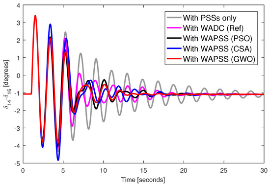
Figure 2.
Angular response from generator 14.
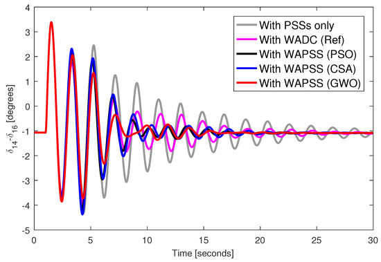
Figure 3.
Angular response from generator 14 with permanent loss of speed signal from generator 14.
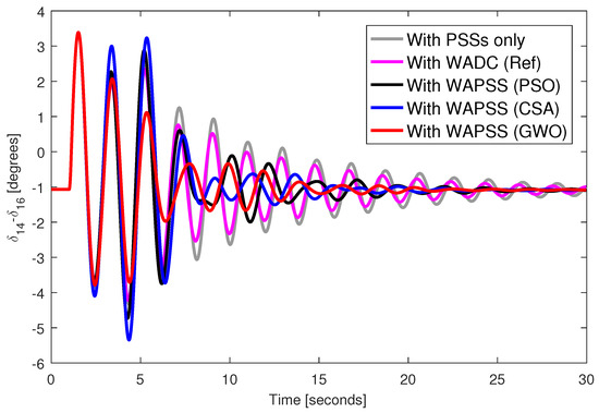
Figure 4.
Angular response from generator 14 with permanent loss of control signal to AVR from generator 5.
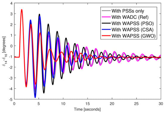
Figure 5.
Angular response from generator 14 with permanent loss of control signal to AVR from generator 5 and speed signal from generator 14.
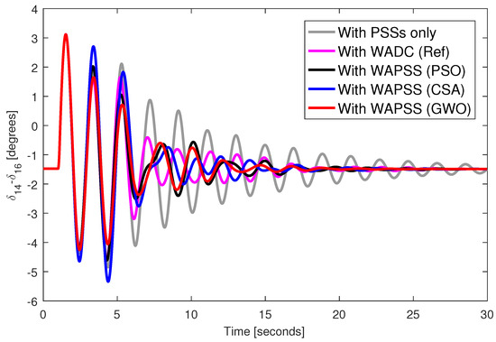
Figure 6.
Angular response from generator 14 and disconnection of the transmission line 31–53.
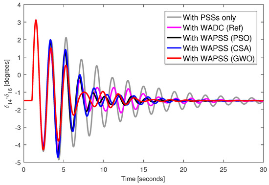
Figure 7.
Angular response from generator 14 with permanent loss of speed signal from generator 14 and disconnection of the transmission line 31–53.
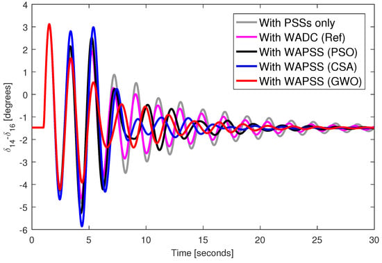
Figure 8.
Angular response from generator 14 with permanent loss of control signal to AVR from generator 5 and disconnection of the transmission line 31–53.
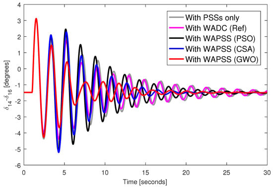
Figure 9.
Angular response from generator 14 with permanent loss of control signal to AVR from generator 5 and speed signal from generator 14 and disconnection of the transmission line 31–53.
5. Conclusions
This work proposes a WAPSS design method robust to multiple communication failures based on an optimization model. The developed method and the results showed the possibility of considering multiple communication failures, but the greater the number of combinations of communication failures, the longer the simulation time of the algorithm and the lower the damping rates of the eigenvalues of the closed-loop control system. Thus, it is not possible to consider several communication failures because the design and performance of the WAPSS will not be viable. The metaheuristics applied in the optimization model for the WAPSS design were effective with a slight superiority of the GWO. It was observed through the achieved results that the random initial conditions of the variables of the optimization problem result in WAPSS-type controllers with different performances and thus different simulations may be necessary to reach a desired WAPSS. Furthermore, different metaheuristics provide different performance and thus the choice of metaheuristic is fundamental for solving the optimization model. Dynamic simulations showed the ability of the closed-loop control system to present well-damped angular responses even in the event of permanent communication failures.
Funding
This research was funded by the Coordenação de Aperfeiçoamento de Pessoal de Nível Superior—Brasil (CAPES)—Finance Code 001.
Institutional Review Board Statement
Not applicable.
Informed Consent Statement
Not applicable.
Data Availability Statement
Not applicable.
Conflicts of Interest
The authors declare no conflict of interest. The funders had no role in the design of the study; in the collection, analyses, or interpretation of data; in the writing of the manuscript; or in the decision to publish the results.
Abbreviations
The following abbreviations are used in this manuscript:
| AVR | Automatic Voltage Regulator |
| CSA | Crow Search Algorithm |
| GWO | Grey Wolf Optimizer |
| LMI | Linear Matrix Inequality |
| LQR | Linear Quadratic Regulator |
| PMU | Phasor Measurement Unit |
| PSO | Particle Swarm Optimization |
| PSS | Power System Stabilizer |
| WADC | Wide-Area Damping Controller |
| WAPSS | Wide-Area Power System Stabilizer |
References
- Nazir, Z.; Bollen, M.H.J. Graphical Ways to Visualize Operational Risk Results for Transmission System Contingencies. Electricity 2022, 3, 442–462. [Google Scholar] [CrossRef]
- Rwamurangwa, E.; Gonzalez, J.D.; Butare, A. Integration of EV in the Grid Management: The Grid Behavior in Case of Simultaneous EV Charging-Discharging with the PV Solar Energy Injection. Electricity 2022, 3, 563–585. [Google Scholar] [CrossRef]
- Guerrero, J.D.A.; Acker, T.L.; Castro, R. Power System Impacts of Electric Vehicle Charging Strategies. Electricity 2022, 3, 297–324. [Google Scholar] [CrossRef]
- Nazir, Z.; Bollen, M.H.J. Investigating Various Severity Factor Behaviors for Operational Risk Assessment. Electricity 2022, 3, 325–345. [Google Scholar] [CrossRef]
- Rogers, G. Power System Oscillations; Springer: New York, NY, USA, 2000. [Google Scholar] [CrossRef]
- Peres, W.; Coelho, F.C.R.; Costa, J.N.N. A pole placement approach for multi-band power system stabilizer tuning. Int. Trans. Electr. Energy Syst. 2020, 30, e12548. [Google Scholar] [CrossRef]
- Bento, M.E.C.; Dotta, D.; Kuiava, R.; Ramos, R.A. Robust design of coordinated decentralized damping controllers for power systems. Int. J. Adv. Manuf. Technol. 2018, 99, 2035–2044. [Google Scholar] [CrossRef]
- Bayu, E.S.; Khan, B.; Ali, Z.M.; Alaas, Z.M.; Mahela, O.P. Mitigation of Low-Frequency Oscillation in Power Systems through Optimal Design of Power System Stabilizer Employing ALO. Energies 2022, 15, 3809. [Google Scholar] [CrossRef]
- Alhelou, H.H.; Abdelaziz, A.Y.; Siano, P. (Eds.) Wide Area Power Systems Stability, Protection, and Security; Power Systems; Springer International Publishing: Cham, Switzerland, 2021. [Google Scholar] [CrossRef]
- Bento, M.E.C. Monitoring of the power system load margin based on a machine learning technique. Electr. Eng. 2022, 104, 249–258. [Google Scholar] [CrossRef]
- Bento, M.E.C.; Ramos, R.A. An approach for monitoring and updating the load margin of power systems in dynamic security assessment. Electr. Power Syst. Res. 2021, 198, 107365. [Google Scholar] [CrossRef]
- Bento, M.E.C. A method for monitoring the load margin of power systems under load growth variations. Sustain. Energy Grids Netw. 2022, 30, 100677. [Google Scholar] [CrossRef]
- Ibarra, L.; Aviles, J.; Guillen, D.; Mayo-Maldonado, J.; Valdez-Resendiz, J.; Ponce, P. Optimal micro-PMU placement and virtualization for distribution network changing topologies. Sustain. Energy Grids Netw. 2021, 27, 100510. [Google Scholar] [CrossRef]
- Bento, M.E.C. Physics-Guided Neural Network for Load Margin Assessment of Power Systems. IEEE Trans. Power Syst. 2023, 1, 1–12. [Google Scholar] [CrossRef]
- Lopez, G.J.; González, J.W.; Isaac, I.A.; Cardona, H.A.; Vasco, O.H. Voltage Stability Control Based on Angular Indexes from Stationary Analysis. Energies 2022, 15, 7255. [Google Scholar] [CrossRef]
- Bento, M.E.C.; Dotta, D.; Ramos, R.A. Performance analysis of Wide-Area Damping Control Design methods. In Proceedings of the 2016 IEEE Power and Energy Society General Meeting (PESGM), Boston, MA, USA, 17–21 July 2016; IEEE: Piscataway, NJ, USA, 2016; pp. 1–5. [Google Scholar] [CrossRef]
- Yaqub, R. Phasor Measurement Unit Assisted Inverter—A Novel Approach for DC Microgrids Performance Enhancement. Electricity 2021, 2, 330–341. [Google Scholar] [CrossRef]
- Bento, M.E.C. An Optimization Approach for the Wide-Area Damping Control Design. In Proceedings of the 2018 13th IEEE International Conference on Industry Applications (INDUSCON), Sao Paulo, Brazil, 12–14 November 2018; pp. 269–276. [Google Scholar] [CrossRef]
- Azhar, I.F.; Putranto, L.M.; Irnawan, R. Development of PMU-Based Transient Stability Detection Methods Using CNN-LSTM Considering Time Series Data Measurement. Energies 2022, 15, 8241. [Google Scholar] [CrossRef]
- Imris, P.; Taylor, G.A.; Bradley, M.E.; Li, Y. A Novel Hardware-in-the-Loop Approach to Investigate the Impact of Low System Inertia on RoCoF Relay Settings. Energies 2022, 15, 6386. [Google Scholar] [CrossRef]
- Hurtado, A.A.P.; Carrasco, E.M.; Martinez, M.T.V.; Saldana, J. Application of IIA Method and Virtual Bus Theory for Backup Protection of a Zone Using PMU Data in a WAMPAC System. Energies 2022, 15, 3470. [Google Scholar] [CrossRef]
- Dotta, D.; e Silva, A.S.; Decker, I.C. Wide-Area Measurements-Based Two-Level Control Design Considering Signal Transmission Delay. IEEE Trans. Power Syst. 2009, 24, 208–216. [Google Scholar] [CrossRef]
- Dehghani, M.; Rezaei, M.; Shayanfard, B.; Vafamand, N.; Javadi, M.; Catalao, J.P.S. PMU-Based Power System Stabilizer Design: Optimal Signal Selection and Controller Design. IEEE Trans. Ind. Appl. 2021, 57, 5677–5686. [Google Scholar] [CrossRef]
- Prakash, A.; Kumar, K.; Parida, S.K. A Modal Transformation Approach to Design Reduced Order Functional Observer-Based WADC for Low-Frequency Oscillations. IEEE Trans. Power Syst. 2022, 1, 1–12. [Google Scholar] [CrossRef]
- Bento, M.E.C. Design analysis of wide-area damping controllers using genetic algorithms. In Proceedings of the 2016 12th IEEE International Conference on Industry Applications (INDUSCON), Curitiba, Brazil, 20–23 November 2016; pp. 1–8. [Google Scholar] [CrossRef]
- Gupta, P.; Pal, A.; Vittal, V. Coordinated Wide-Area Damping Control Using Deep Neural Networks and Reinforcement Learning. IEEE Trans. Power Syst. 2022, 37, 365–376. [Google Scholar] [CrossRef]
- Prakash, A.; Singh, P.; Kumar, K.; Parida, S.K. Design of a Reduced-Order WADC for Wind Turbine System-Integrated Power System. IEEE Trans. Ind. Appl. 2022, 58, 3250–3260. [Google Scholar] [CrossRef]
- Bento, M.E.C. A procedure to design wide-area damping controllers for power system oscillations considering promising input–output pairs. Energy Syst. 2019, 10, 911–940. [Google Scholar] [CrossRef]
- Milano, F.; Anghel, M. Impact of Time Delays on Power System Stability. IEEE Trans. Circuits Syst. I Regul. Pap. 2012, 59, 889–900. [Google Scholar] [CrossRef]
- Saraf, P.; Balasubramaniam, K.; Hadidi, R.; Makram, E. Design of a wide area damping controller based on partial right eigenstructure assignment. Electr. Power Syst. Res. 2016, 134, 134–144. [Google Scholar] [CrossRef]
- Darabian, M.; Bagheri, A. Design of adaptive wide-area damping controller based on delay scheduling for improving small-signal oscillations. Int. J. Electr. Power Energy Syst. 2021, 133, 107224. [Google Scholar] [CrossRef]
- Darabian, M.; Bagheri, A. Stability improvement of large-scale power systems including offshore wind farms and MTDC grid aiming at compensation of time delay in sending robust damping signals. Int. J. Electr. Power Energy Syst. 2022, 143, 108491. [Google Scholar] [CrossRef]
- Liang, G.; Weller, S.R.; Zhao, J.; Luo, F.; Dong, Z.Y. The 2015 Ukraine Blackout: Implications for False Data Injection Attacks. IEEE Trans. Power Syst. 2017, 32, 3317–3318. [Google Scholar] [CrossRef]
- Liu, S.; Liu, X.P.; Saddik, A.E. Denial-of-Service (dos) attacks on load frequency control in smart grids. In Proceedings of the 2013 IEEE PES Innovative Smart Grid Technologies Conference (ISGT), Washington, DC, USA, 24–27 February 2013; IEEE: Piscataway, NJ, USA, 2013. [Google Scholar] [CrossRef]
- Bento, M.E.C. Fixed Low-Order Wide-Area Damping Controller Considering Time Delays and Power System Operation Uncertainties. IEEE Trans. Power Syst. 2020, 35, 3918–3926. [Google Scholar] [CrossRef]
- Bento, M.E.C.; Ramos, R.A. A Method Based on Linear Matrix Inequalities to Design a Wide-Area Damping Controller Resilient to Permanent Communication Failures. IEEE Syst. J. 2021, 15, 3832–3840. [Google Scholar] [CrossRef]
- Bento, M.E.C. Design of a wide-area damping controller to tolerate permanent communication failure and time delay uncertainties. Energy Syst. 2022, 13, 235–264. [Google Scholar] [CrossRef]
- Bento, M.E.C.; Dotta, D.; Kuiava, R.; Ramos, R.A. A Procedure to Design Fault-Tolerant Wide-Area Damping Controllers. IEEE Access 2018, 6, 23383–23405. [Google Scholar] [CrossRef]
- Bento, M.E.C. Resilient Wide-Area Damping Controller Design Using Crow Search Algorithm. IFAC-PapersOnLine 2022, 55, 938–943. [Google Scholar] [CrossRef]
- Liu, S.; Zenelis, I.; Li, Y.; Wang, X.; Li, Q.; Zhu, L. Markov Game for Securing Wide-Area Damping Control Against False Data Injection Attacks. IEEE Syst. J. 2021, 15, 1356–1365. [Google Scholar] [CrossRef]
- Yao, W.; Nan, J.; Zhao, Y.; Fang, J.; Ai, X.; Zuo, W.; Wen, J.; Cheng, S. Resilient Wide-Area Damping Control for Inter-Area Oscillations to Tolerate Deception Attacks. IEEE Trans. Smart Grid 2021, 12, 4238–4249. [Google Scholar] [CrossRef]
- Jha, M.; Chakrabarti, S.; Kyriakides, E. Estimation of the rotor angle of a synchronous generator by using PMU measurements. In Proceedings of the 2015 IEEE Eindhoven PowerTech, Eindhoven, The Netherlands, 29 June–2 July 2015; pp. 1–6. [Google Scholar] [CrossRef]
- Kumar, M.; Affijulla, S. On-line estimation of alternators rotor angle dynamics in the modern power system. Int. J. Electr. Power Energy Syst. 2022, 134, 107314. [Google Scholar] [CrossRef]
- Parreiras, T.J.M.A.; Gomes, S.; do Amaral, T.S.; da Costa, M.R.; Netto, N.A.R.L. Online Monitoring of Oscillation Modes for Small-signal Security Assessment. IEEE Trans. Power Syst. 2023, 1, 1–10. [Google Scholar] [CrossRef]
- Kennedy, J.; Eberhart, R. Particle swarm optimization. In Proceedings of the ICNN95—International Conference on Neural Networks, Perth, WA, Australia, 27 November–1 December 1995; IEEE: Piscataway, NJ, USA, 1995. [Google Scholar] [CrossRef]
- Askarzadeh, A. A novel metaheuristic method for solving constrained engineering optimization problems: Crow search algorithm. Comput. Struct. 2016, 169, 1–12. [Google Scholar] [CrossRef]
- Mirjalili, S.; Mirjalili, S.M.; Lewis, A. Grey Wolf Optimizer. Adv. Eng. Softw. 2014, 69, 46–61. [Google Scholar] [CrossRef]
- Al-Tameemi, Z.H.A.; Lie, T.T.; Foo, G.; Blaabjerg, F. Optimal Coordinated Control of DC Microgrid Based on Hybrid PSO-GWO Algorithm. Electricity 2022, 3, 346–364. [Google Scholar] [CrossRef]
- Islam, J.; Rahaman, M.S.A.; Vasant, P.M.; Negash, B.M.; Hoqe, A.; Alhitmi, H.K.; Watada, J. A Modified Niching Crow Search Approach to Well Placement Optimization. Energies 2021, 14, 857. [Google Scholar] [CrossRef]
- Maihemuti, S.; Wang, W.; Wu, J.; Wang, H.; Muhedaner, M. New Energy Power System Static Security and Stability Region Calculation Research Based on IPSO-RLS Hybrid Algorithm. Energies 2022, 15, 9655. [Google Scholar] [CrossRef]
- Rajagopalan, A.; Nagarajan, K.; Montoya, O.D.; Dhanasekaran, S.; Kareem, I.A.; Perumal, A.S.; Lakshmaiya, N.; Paramasivam, P. Multi-Objective Optimal Scheduling of a Microgrid Using Oppositional Gradient-Based Grey Wolf Optimizer. Energies 2022, 15, 9024. [Google Scholar] [CrossRef]
- Xu, W.; Yu, B.; Song, Q.; Weng, L.; Luo, M.; Zhang, F. Economic and Low-Carbon-Oriented Distribution Network Planning Considering the Uncertainties of Photovoltaic Generation and Load Demand to Achieve Their Reliability. Energies 2022, 15, 9639. [Google Scholar] [CrossRef]
- Chen, K.; Peng, H.; Gao, Z.; Zhang, J.; Chen, P.; Ruan, J.; Li, B.; Wang, Y. Day-Ahead Operation Analysis of Wind and Solar Power Generation Coupled with Hydrogen Energy Storage System Based on Adaptive Simulated Annealing Particle Swarm Algorithm. Energies 2022, 15, 9581. [Google Scholar] [CrossRef]
- Canizares, C.; Fernandes, T.; Geraldi, E.; Gerin-Lajoie, L.; Gibbard, M.; Hiskens, I.; Kersulis, J.; Kuiava, R.; Lima, L.; DeMarco, F. Benchmark Models for the Analysis and Control of Small-Signal Oscillatory Dynamics in Power Systems. IEEE Trans. Power Syst. 2017, 32, 715–722. [Google Scholar] [CrossRef]
- Bento, M.E.C. A hybrid procedure to design a wide-area damping controller robust to permanent failure of the communication channels and power system operation uncertainties. Int. J. Electr. Power Energy Syst. 2019, 110, 118–135. [Google Scholar] [CrossRef]
Disclaimer/Publisher’s Note: The statements, opinions and data contained in all publications are solely those of the individual author(s) and contributor(s) and not of MDPI and/or the editor(s). MDPI and/or the editor(s) disclaim responsibility for any injury to people or property resulting from any ideas, methods, instructions or products referred to in the content. |
© 2023 by the author. Licensee MDPI, Basel, Switzerland. This article is an open access article distributed under the terms and conditions of the Creative Commons Attribution (CC BY) license (https://creativecommons.org/licenses/by/4.0/).