1. Introduction
The following paper shows an initial process concept for the reengineered Pedersen Process [
1]. The design capacity for the investigated case is 500 kt of industrial-grade alumina. The present data are based on the last three and a half years of research within the European Commission-funded ENSUREAL project. The presented process flow diagram is a preliminary concept developed during an ongoing upscaling procedure. Generated know-how is used to identify appropriate industrial scale process equipment.
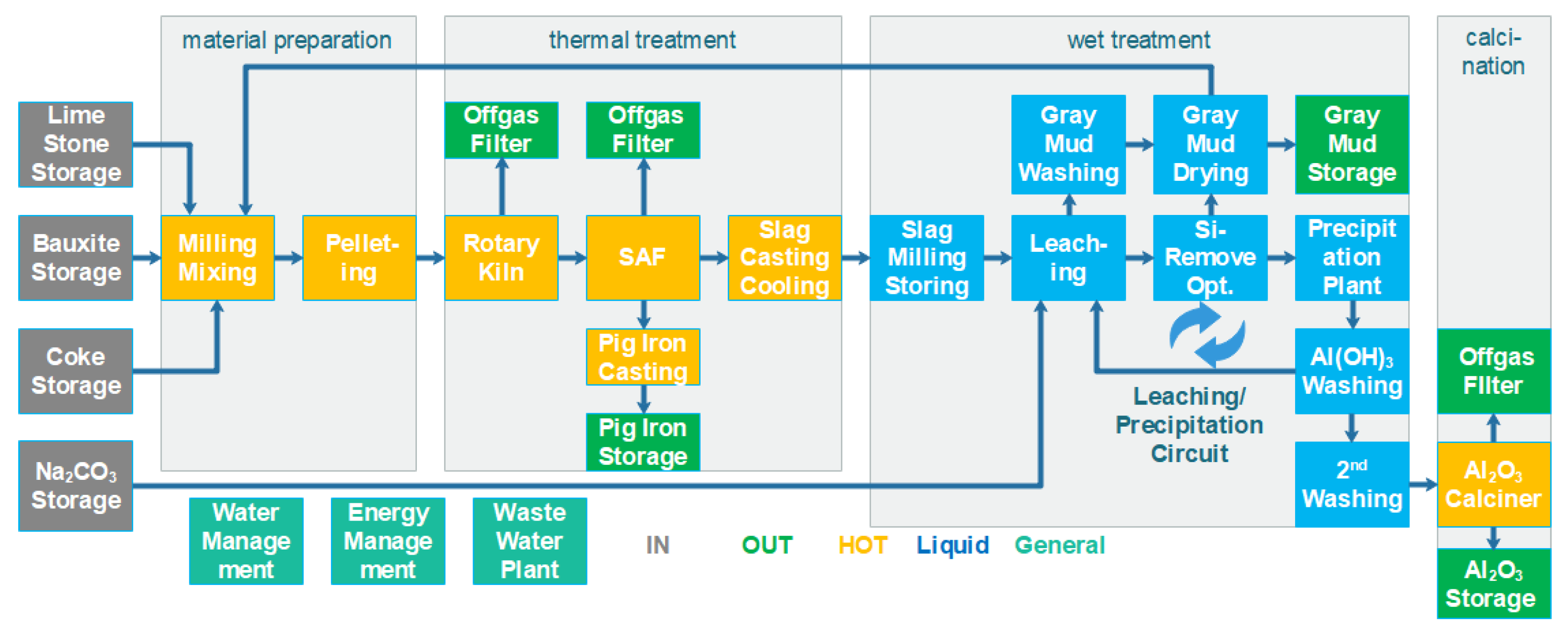
The industrial concept consists of four main sections: material preparation, thermal treatment, wet treatment and calcination. The block flow concept is shown in
Figure 1.
Within the material preparation phase, bauxite or bauxite residue, limestone, coke and an internally recycled gray mud stream are mixed, milled and formed into pellets. The reason for pellet generation is to have a homogenous feed stream to the hot section and a reduced dust load within the process.
During the thermal treatment, the pellets are dried and hardened inside the preheating kiln and the iron fraction is partly reduced to metallic iron. The hot pellets are then directly transferred to the electrical furnace where, at >1500 °C, pig iron and a CaAl slag with specific properties are produced. The pig iron is the first product of the process and the CaAl slag is cooled down at rates that allow formation of leachable crystal phases.
Within the wet section, leaching of the CaAl slag using a recycled Na2CO3 solution takes place. During leaching, solid gray mud (CaCO3) and dissolved NaAlO2 are formed. This is the key purification step. The NaAlO2 solution is then treated with CO2 so that dissolved Na2CO3 and solid Al(OH)3 are formed. By transferring the Na2CO3 solution back to the leaching stage, the wet cycle is closed.
Lastly, generated Al(OH)3 is transferred to the calcination step where a proven fluidized bed process produces smelter-grade alumina.
The advantage of the Pedersen Process is flexibility in the raw materials used. It is also a zero-waste process. Through smart CO2 management, the Pedersen Process can even become a CO2-negative process.
2. Materials and Methods
The basement of each industrial scale process development is a deep process understanding. A preliminary mass and energy balance allowing the testing of single process parameters is essential. One of the pillars of this work is a mass and energy balance model which was developed in the Outotec HSC environment that has previously been presented at the BR2020 Conference [
2].
The current concept assumes tropical bauxite and limestone as main feed materials. A standard coke prepares the reduction potential for treating the iron fraction and producing pig iron. The gray mud backflow is fixed by definition at 40%, which means that the calcium source (limestone + gray mud) is 60% m/m limestone and 40% m/m gray mud. The chemical composition of the streams is shown in
Table 1. The given numbers are not fixed permanently; they are based on a normal variation of the chemistry of natural resources and the gray mud recycle will vary significantly.
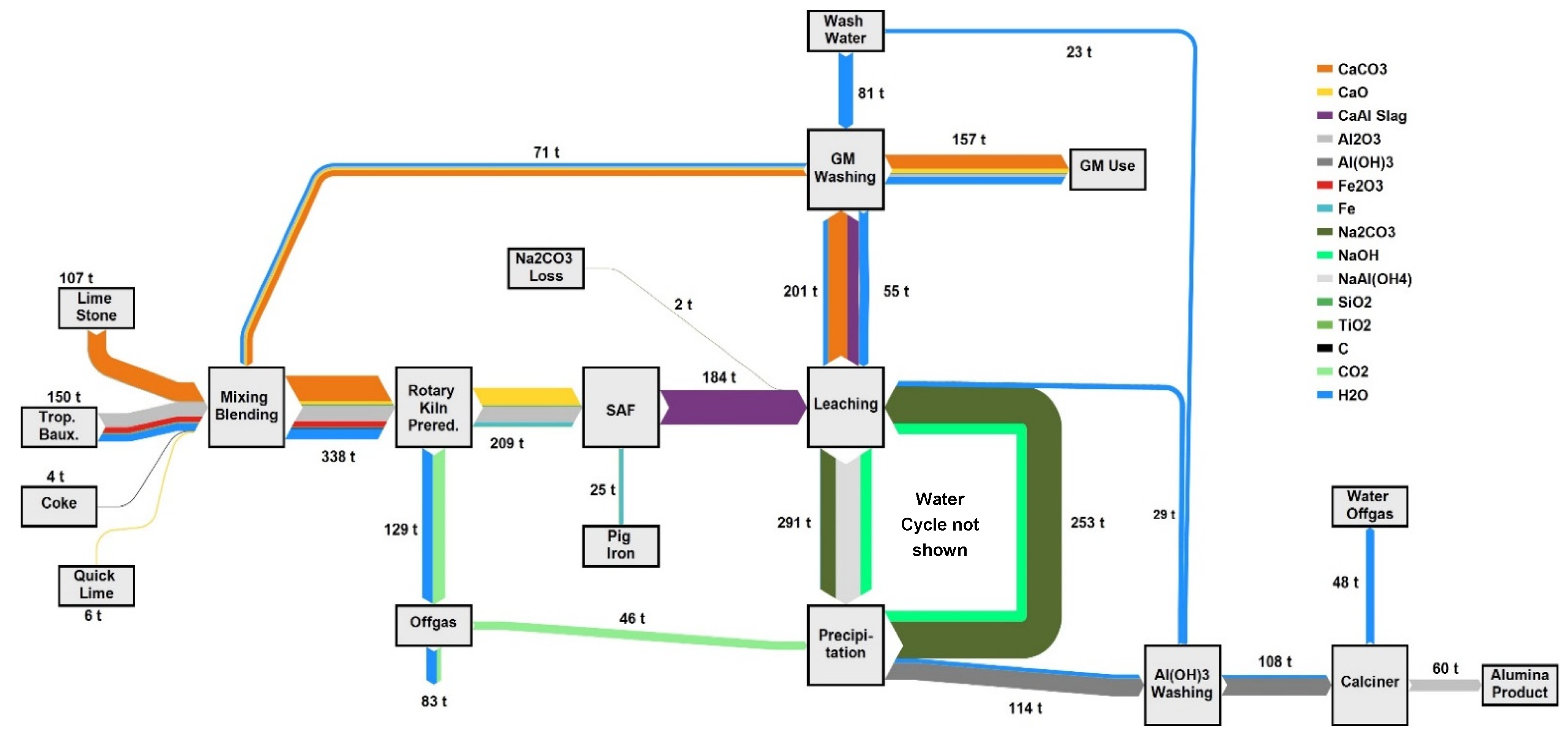
For the design of a process, the absolute number is not of great importance. Defining the accepted range for certain process parameters is the key to equipment decisions and process design. The mass stream results of one design case are shown in the Sankey diagram in
Figure 2. To reach an annual alumina output of 500,000 t Al
2O
3 and assuming an annual process availability of 95%, the product output must be fixed at 60 t/h. Considering the lab tests at NTUA and NTNU show a leaching efficiency of 70%, a precipitation efficiency of >99% and the previously mentioned gray mud backflow, 107 t/h limestone, 150 t/h tropical bauxite, 4 t/h coke and 6 t/h quicklime must be fed to the plant. The quicklime is used to improve the pelleting process
The gray mud also contains some alumina that is not leached, and by having a recycling stream, this alumina portion is held within the process boundaries and the overall alumina yield is increased to 79%.
3. Results
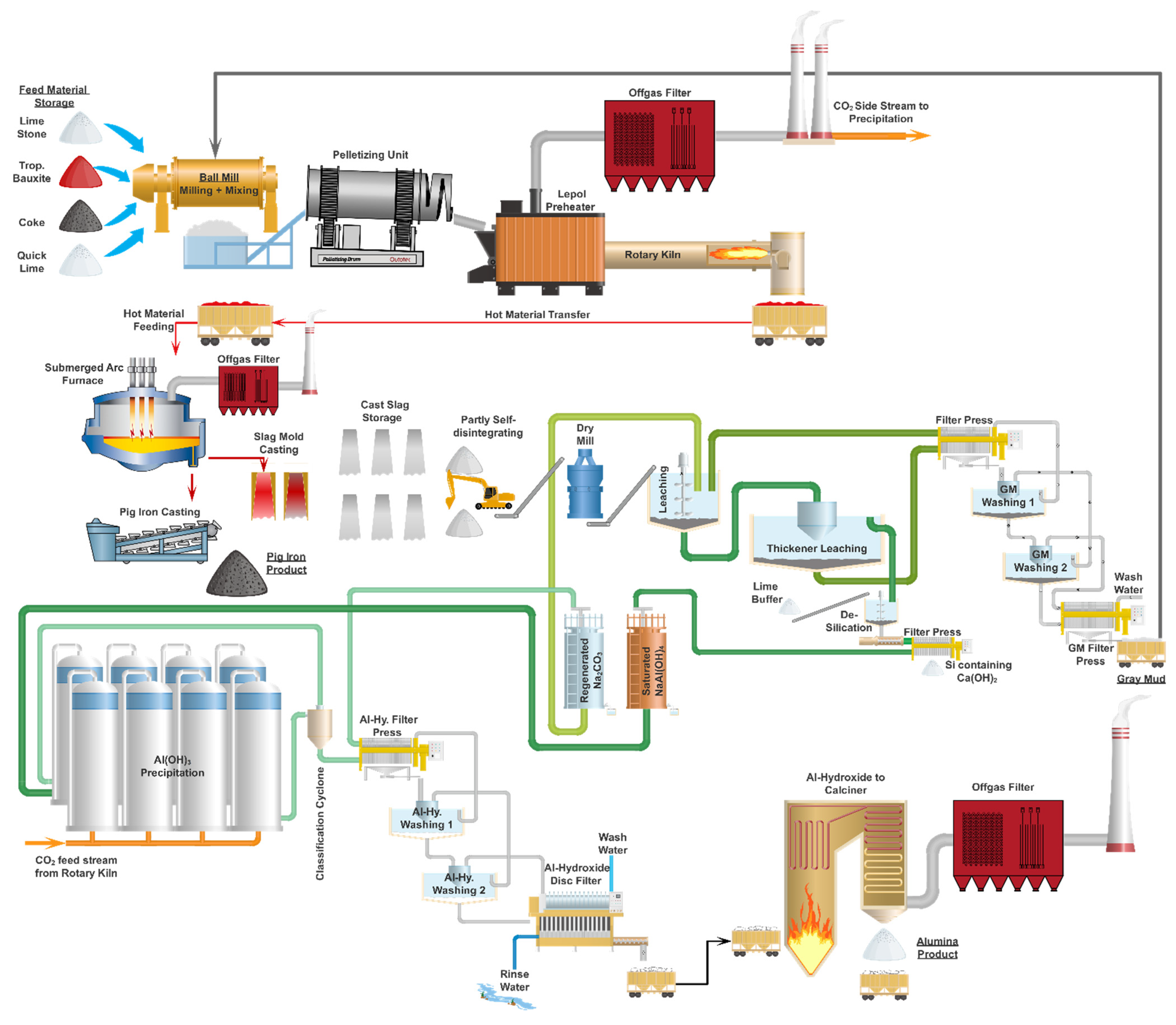
The illustrated process concept in
Figure 3 is the current result of the ongoing development work. The following subtasks describe the key process steps, equipment used as well as the industrial scale concept.
3.1. Milling
Bauxite, limestone, coke, quicklime and the water containing gray mud backflow are continuously fed to the ball mill. To handle the total mass flow of more than 300 t/h, two parallel lines will be installed. The ball mill mills and mixes the material until fractions are fine enough for the next processing step and a homogenous mixture is reached. Wide particle size distribution is also important for a stable pelleting process. The milling is a dry process and a maximum moisture level in the input materials will be determined and fixed during a later detail engineering process.
3.2. Pelleting
Handling powdery material is an especially challenging task in the smelting process, as it carries the risk of discharging material to the filter system. By adding a mixture of materials with different specific gravities and particle sizes, there is the additional risk that only specific material fractions will be discharged, negatively affecting the process recipe.
To overcome this issue, a pelleting process will be implemented. The aim is to ensure that the feed material has a pellet size between 5 and 20 mm and that it reaches a defined composition. The pelleting will take place in two parallel-operated disk or drum pelletizing units. The quicklime combined with a fine water spray will lead to a controlled pelleting process. It is crucial to achieve a certain green strength within the pellets to prevent them from breaking during a handling procedure. Storage of the green pellets is not possible due to a limited pouring height; additionally, a potential drying-out of the pellets during storage would result in reduced strength and transportability.
3.3. Calcination
The produced pellets are transferred to the calcination system, which consists of two parallel lines consisting of a Lepol preheater and a rotary kiln. The Lepol preheater is a moving belt system that uses the hot gases from the rotary kiln to dry and preheat the pellets under controlled conditions, applying minimal mechanical stress and allowing them to generate mechanical strength.
After the preheating, pellets are directly delivered to the rotary kiln. The kiln is operated in a temperature range between 600 and 1200 °C where at least a partial reduction of the iron phase and a calcination of the calcium phase take place. The CO2-enriched gases are treated in a filter and then used in the precipitation stage (Stage 3.9 below). The overall CO2 balance benefits from this internal process loop. There is no product cooler installed within that system; a hot material transfer to the submerged arc furnace (SAF) occurs.
3.4. Slag Engineering
The slag engineering occurs in two parallel-operated SAFs [
3]. The hot pre-calcined material is fed to the system and, at temperatures above 1500 °C, the iron phase is fully melted and separated as pig iron. The pig iron is cast as the first product of the reengineered Pedersen Process.
The basic recipe for the slag is already defined within Stage 3.1. A fine-tuning of the slag during the smelting procedure in the industrial process might be possible and must be further investigated. After finalizing the defined smelting procedure, the hot slag is cast into molds.
3.5. Slag Cooling
The cooling step is a critical step in the process; the formed crystal structure significantly affects later leaching behavior. In general, a slow cooling is preferred. By using molds of a certain size and not applying forced cooling, the stored energy is sufficient for a slow cooling process.
Once a certain mechanical stability is achieved at the end of the first cooling period, the molds are separated from the slag ingot and directly used for the next casting procedure. The slag cools further; a self-disintegration process will also take place. Within the current development stage, a 100% self-disintegration cannot be guaranteed, so a flexible wheel loader will be utilized to transfer the slag to the next processing step.
3.6. Milling
During the milling step, the partially self-disintegrated slag is brought to a particle size < 200 µm so that a homogeneous and easy-to-handle material can be treated within the hydrometallurgical process section.
3.7. Leaching
The leaching is executed in the recycled sodium carbonate Na
2CO
3 solution coming from the precipitation stage (Stage 3.9 below) [
4]. The slag is a mixture of different CA phases, and formula 1 shows one case of dissolving a specific phase as an example [
5].
All the dissolving reactions of the main components result in sodium aluminate NaAl(OH)
4 and solid calcium carbonate CaCO
3. The temperature range for the leaching is 70 to 90 °C and the setup must consist of at least one leaching reactor and one settling reactor, which also generates retention time. This aligns with the original Pedersen Process [
6]. A two-stage counter-current leaching setup for the industrial process concept is under discussion; the final decision has not yet been made. The two-stage concept was previously investigated by the U.S. Bureau of Mines [
7]. Sodium losses, which mainly take place via formed sodium silicates Na
2SiO
3, are offset by adding extra Na
2CO
3 into the leaching reactor. The generated CaCO
3, called gray mud (GM), is separated from the solution and treated in multiple counter-current washing stages to reduce the loss of reactive chemicals. The current Al yield is around 70%, but by adjusting the GM backflow volume, the process Al yield can exceed 80%. A full internal GM recycling is not possible due to the enrichment of trace elements such as Si and Ti. The non-recycled GM is the second product of the process and can be used as fertilizer or in the cement industry.
3.8. Silica Removal
Depending on the raw material used [
7], a silica removal step might be required to reach the necessary alumina purity. The silica removal is carried out by adding quicklime to the pregnant sodium aluminate solution. The filter cake generated within this process step will be discharged and united with the GM product. During the silica removal, regenerated Al losses will be an important topic for further optimization procedures.
3.9. Precipitation
The purified pregnant NaAl(OH)
4 solution is treated with CO
2 gas to form alumina hydroxide Al(OH)
3 and the regenerated Na
2CO
3 solution. This process step follows in formula 2:
The precipitation will be executed at a temperature level below 40 °C to generate the phase shown. As a CO2 source it is possible to use the off-gas from Stage 3.3 to reduce the overall CO2 emission level. The particle size and mechanical stability are of special importance within the industrial process. Similar to the Bayer Process, a large holdup volume will be required to give the particles the required time to grow. After precipitation, a hydrocyclone size classification is executed and the fines are recirculated and used as seeds for the precipitation. The particles of the proper size are further treated in the counter-current-operated washing section. Within a final disc filter system, the Al(OH)3 is separated as filter cake with relatively low remaining moisture due to the large particle size.
3.10. Calcination
To produce the final alumina Al2O3, a standard circulating fluidized bed system will be used. Through intensive preheating and energy recovery steps, the required energy consumption will be brought to a minimum. As an important precondition for this final treatment step, the produced Al(OH)3 particle requires a certain size and mechanical resistance.
4. Discussion
The presented Pedersen Process concept is an interesting starting point and also offers the advantage of several further improvement steps. Compared with the Bayer Process, the raw material (bauxite) will be valorized to a much higher percentage since the iron fraction becomes a product instead of waste. Additionally, other aspects might be useful for a more sustainable future in alumina processing. Within the ENSUREAL project, some tests for the use of low CO2 off-gases for the precipitation were performed. Assuming a symbiosis of different industries, it might be possible for the Pedersen Lepol and rotary kiln to be executed as an oxyfuel process that generates an off-gas which allows an easy carbon capture and storage CCS approach. By using another off-gas for the precipitation step, the CO2 balance can be reduced or even become negative.
Additionally, within the ENSUREAL project, the use of bauxite residues as feed material was successfully demonstrated. A possible further commercialization of the process using bauxite residues and a parallel installation of a Bayer and a Pedersen Process line could be an interesting opportunity.
5. Conclusions
The Pedersen Process is an interesting and promising alternative or addition to the Bayer Process route to produce metallurgical-grade alumina. Reflecting the ongoing trend toward electrification [
8] and assuming the use of renewables, the Pedersen Process is in line with current developments. The ENSUREAL project developed and revitalized a solid base of knowledge required for following steps. The team is looking forward to realizing an industrial alumina plant based on this technology, operating for more than 8300 h per year continuously for decades to come.


 ,
, 

