Abstract
The Pedersen process is an alumina production process, which combines pyrometallurgical and hydrometallurgical methods. In the pyrometallurgical stage, limestone is calcined and CO2 is generated. This off-gas can be captured with a high CO2 concentration. At the end of the hydrometallurgical process, aluminum hydroxides, like bayerite, are precipitated using CO2. In this paper, experimental work on precipitation of aluminum hydroxides through the addition of a mixture of CO2, O2 and N2 is presented. The parameters varied, as were the percentages of each gas and the temperature. The indicators measured were the time until the beginning of precipitation and the time that the precipitation lasts. These tests simulate the use of a smelter furnace off-gas in the precipitation stage of the Pedersen process and have shown promising results.
1. Introduction
The objective of the presented work is to study the precipitation of aluminum hydroxides through the addition of a mixture of CO2, O2 and N2. Experiments took place using a range of percentages of each gas, at temperatures of 40, 50 and 60 °C. Following the conditions of each experiment, the time until precipitation start, after the carbonation, varies. Another indicator measured was the time from start to the end of the precipitation. This research was done in the framework of the ENSUREAL project, the aim of which is to ensure the zero-waste production of alumina in Europe [1,2,3]. The integration of carbon capture and usage from an industrial off-gas with low CO2 concentration into the Pedersen process is a major innovation compared to the original process and can make it competitive with the Bayer process.
2. Materials and Methods
The solution was produced by leaching a slag with a composition listed in Table 1. The slag was made by smelting bauxite ore, provided by Aluminium of Greece (AoG), mixed with CaO. The slag was produced by SINTEF, as a part of a set of pilot-scale experiments. The slag consisted mostly of Al and Ca in the form of mayenite Ca12Al14O33 and a small amount of tri-calcium aluminate minerals Ca3Al2O6, Ca-silicates and perovskite. The slag was leached using 60 g/L Na2CO3 solution at 90 °C for 1 h using a solid to liquid ratio of 300 g of slag to 2 L of solution. The resulting solution has chemistry, described in detail in Table 2 below. The solution was not desilicated, and this explains the high value of Si. The precipitation experiments were conducted in a 1 L jacketed glass reactor. The gas mixtures were sparged into the solution at a rate of 1.5 L/min through plastic tubing that entered the reactor through an inlet port on the reactor lid. The temperature is controlled by circulating heated silicon oil, through the reactor jacket. The volume of the solution at elevated temperatures was maintained using a water cooled condenser and the temperature of the solution was monitored using a temperature probe. The entire set up can be seen in Figure 1.

Table 1.
XRF analysis of the leached slag (wt%).
Table 2.
Solution’s composition.
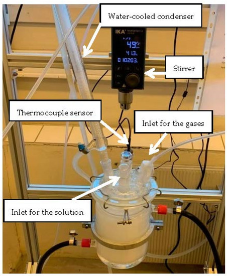
Figure 1.
Reactor.
When the desired temperature is reached, gases are injected at a constant flow, controlled by a gas flowmeter. The study consisted of 13 experiments, listed in Table 3.
Table 3.
Experimental plan: Gas composition and temperatures.
All 13 experiments followed the same procedure. The solution in the reactor was heated to a temperature of 40 °C. This took one hour or more. A sample was taken to be analyzed by ICP-MS method. When the temperature reached 30 °C the water flow through the condenser was allowed. When the temperature reached 40 °C the mixture of gases was injected into the solution. The time until the precipitation starts was measured. After the precipitation started, the carbonation was allowed to proceed for a certain period of time. After this, the gas flow to the solution was stopped. The solution with the newly formed precipitate was allowed to stand for a period of 24 h, a process referred to as aging. This step is necessary to convert the precipitates, mostly in the form of boehmite, to the desired aluminium tri-hydroxides. After this, the slurry was vacuum filtered in order to separate the solution from the precipitates. The volume of the solution (after the filtration) was measured and another sample was taken for ICP-MS analysis. The filter cake was washed with deionized water. After this procedure, the filter cake was placed in a drier at 60 °C, for 48 h. After two days, the produced filter cake was weighed and sent for XRD, XRF and PSD analyses.
3. Results
The time till the precipitation starts varies in each experiment from 40 min to 2 h and 10 min. It was observed in the first three experiments that the time before the precipitation started was approximately 2 h, whereas in the next two experiments, in which the percentage of CO2 was higher and there was also O2, the time was 45 min. In the 6th experiment, where the CO2 percentage was 8%, the time until the precipitation started was more than 1 h, whereas in the 7th experiment with 12% of CO2, the time was less than 1 h. This means that the higher the percentage of CO2 was, in combination with the presence of O2 gas, the faster the precipitation took place. In the 8th and 9th experiment, with 5% of CO2, even though the temperature was 50 °C and 60 °C respectively, the time before the precipitation started was almost 2 h. In the last four experiments, it was observed that the higher percentages of CO2, with the combination of the high temperatures, made the precipitation commence after less than 1 h. The mass of the precipitate is listed in Table 4 and the results of the XRD analysis are listed in Table 5. The dominant phase in experiments E1–E9 is bayerite, which is the desired phase for the results of the experiments. In experiments E9 to E13, there is a considerable amount of boehmite as well. The results of the XRF method for all the samples can be seen in Table 6. The aim of this analysis is to check the levels of the major contaminants. In an industrial process, a desilication step would be practiced between the leaching and the precipitation step. This has not been done in this small scale set-up. Therefore, the Si content was far above the limit. The results of particle size distribution from the experiments are listed in Table 7, as the D90 and D75 of the particles. On basis of the ICP measurements of the solution before and after the precipitation, the aluminium recovery was calculated. The results are listed in Table 8.
Table 4.
Final mass of precipitate.
Table 5.
XRD results (wt%).
Table 6.
XRF results of main contaminants.
Table 7.
Results from particle size distribution measurements (μm).
Table 8.
Al recovery.
4. Discussion
Regarding the XRF analysis (Table 6), it was observed that especially Si has a higher concentration than the specified limit. In an industrial process, a desilication step with Ca, before precipitation, will be implemented to avoid this high Si content in the precipitates [4]. As far as the particle size distribution is concerned, the desired distribution is that 50% of the particles should be larger than 44 μm. From Table 7, it can be seen that this value has not been reached. The reactor used was small and the particles had not much time to grow before they reached the bottom. From the Bayer process, it is known that the growing of the precipitates is a time consuming process. Therefore, the small size of the reactor has probably contributed to the small size of the precipitates. A larger reactor size will probably increase the particle size. Moreover, seeding with fine-grained aluminum hydroxide crystals, as done in the Bayer process, might increase the size of the particles, as well as decrease the time until the precipitation starts. There is a clear influence of oxygen on the precipitation. Comparison between test 1 to 4 shows that the time until precipitation starts, decreases when oxygen is present. Moreover, the aluminum recovery is improved significantly. The oxygen is most likely not to take part in any chemical reaction but has a catalysing effect on the precipitation. An increased precipitation temperature seems to improve the aluminum recovery rate and also enhances the formation of other phases than bayerite, which is undesirable, as shown in the XRD analysis, from Table 5. The same has been observed previously [5,6], with the formation of other oxides, such as dawsonite.
In order to achieve a higher aluminum recovery, a more thorough investigation needs to be conducted. A longer aging duration would probably lead to a higher recovery and larger particles.
5. Conclusions
The most important finding in this work is that the precipitation of aluminum hydroxides is accelerated by the presence of oxygen. Under the present experimental program, the best conditions for precipitation were: 40 °C, 15% of CO2, 16% of O2 and 69% of N2. In the experiment with these conditions, the percentage of bayerite was 97% wt and the Al recovery was 58.5%. The combination of carbonation and aging has shown that it can produce the desired Al tri-hydroxide precipitates. Longer aging periods are likely to result in an improved precipitation yield of the Al from the solution. As far as the chemical analysis is concerned, it is obvious that further work is needed in order to reduce the concentration of contaminants, but this was outside the scope of this work.
This work has shown that it is possible to use an industrial off-gas for the precipitation stage in the Pedersen process.
In general, this process seems to be very promising for the improvement of the Pedersen process, but it leaves room for further investigation.
Acknowledgments
This project has received funding from the European Union’s Horizon 2020 research and innovation programme under grant agreement No. 767533.
References
- Azof, F.I.; Vafeias, M.; Panias, D.; Safarian, J. The leachability of a ternary CaO-Al2O3-SiO2 slag produced from smelting-reduction of low-grade bauxite for alumina recovery. Hydrometallurgy 2020, 191, 105184. [Google Scholar] [CrossRef]
- Azof, F.I.; Safarian, J. Leaching kinetics and mechanism of slag produced from smelting-reduction of bauxite for alumina recovery. Hydrometallurgy 2020, 195, 105388. [Google Scholar] [CrossRef]
- Lazou, A.; van der Eijk, C.; Tang, K.; Balomenos, E.; Kolbeinsen, L.; Safarian, J. The Utilization of Bauxite Residue with a Calcite-Rich Bauxite Ore in the Pedersen Process for Iron and Alumina Extraction. Metall. Mater. Trans. B 2021, 52, 1255–1266. [Google Scholar] [CrossRef]
- Mwase, J.; Safarian, J. Production of Aluminium Tri-hydroxides from Secondary Bauxite Materials. In Proceedings of the for EMC 2021 European Metallurgical Conference, Virtual Conference, 27–30 June 2021. [Google Scholar]
- Marinos, D.; Vafeias, M.; Sparis, D.; Kotsanis, D.; Balomenos, E.; Panias, D. Parameters affecting the precipitation of Al-phases from aluminate solutions of the Pedersen process. In Proceedings of the 3rd International Bauxite Residue Valorisation and Best Practices Conference, Virtual Event, 29 September–1 October 2020. [Google Scholar]
- Marinos, D.; Kotsanis, D.; Alexandri, A.; Balomenos, E.; Panias, D. Carbonation of sodium aluminate/sodium carbonate solutions for precipitation of alumina hydrates avoiding the dawsonite formation. Crystals 2021, 11, 836. [Google Scholar] [CrossRef]
Publisher’s Note: MDPI stays neutral with regard to jurisdictional claims in published maps and institutional affiliations. |
© 2021 by the authors. Licensee MDPI, Basel, Switzerland. This article is an open access article distributed under the terms and conditions of the Creative Commons Attribution (CC BY) license (https://creativecommons.org/licenses/by/4.0/).