Published: 18 February 2021
1. Introduction
Throughout extrusion, the exit temperature of the profile changes because of the thermodynamic characteristics of the process: predominantly, the temperature of the material increases, causing a nonuniformity of the alloy properties and of the dimension of the profile along the product length. The microstructure of the final length that has been extruded may be characterized by grains with greater dimension than the ones in the other extremity—affecting consequently the mechanical properties—and, if the exit temperature exceeds the alloy melting temperature, the product surface will be marked by surface defects [
1,
2]. Therefore, it is crucial that the exit temperature of the profile is accurately monitored and, if possible, kept constant.
For these reasons isothermal extrusion has been developed [
3,
4]. The billets can be taper-heated, so their temperature changes lengthways—the billet head, the first fraction of material that is deformed, is warmer than the billet foot. Additionally, through a suitable process control, the extrusion speed can be progressively decreased: the regulation on the ram speed is done considering the exit temperature of the product, which is acquired at the outlet of the press [
5,
6]. Moreover, a constant temperature profile can be obtained through a cooling of the die, usually done by means of liquid nitrogen [
7,
8,
9].
Extrusion speed variation technique allows the amount of heat generated to be controlled while with nitrogen cooling systems the exceeding heat is removed: considering the billet taper heating, a proper temperature gradient is able to balance the amount of heat generated during the extrusion process and so the exit temperature of the product will be constant [
10]. Once the best extrusion speed for the selected die is defined, this practice permits an isothermal extrusion keeping the speed constant and so without compromising the plant productivity and the product quality.
During an extrusion process, the amount of generated heat is characterized by two contributing factors, one related to the friction phenomena and one associated with the material deformation. Furthermore, conductive and convective phenomena are established: these phenomena are responsible for heat transfers through the press-system.
Many simulation models were proposed to predict the extrusion process. Abdul-Jawwad et al. [
11] used the statistical design of experiments (DOE) and found that initial billet temperature, ram speed, extrusion ratio, profile average thickness, and number of die cavities influenced the resulting profile exit temperature. The integral profile approach [
12,
13,
14] assumes a temperature profile surrounding the heat source to be given by the expression ∆T = a + bx + cx
2, where a, b, and c are constants determined by boundary conditions, ∆T is the temperature differential driving the heat conduction, and x represents the distance from the heat source. Other works are based on the numerical analysis [
14]. Furthermore, Takashi and Yoneyama [
15] focus their attention on a simple model to achieve isothermal extrusion.
Starting on these findings in the literature, the main goal of this study is the formulation of a model that, on-line, considering all the process variables, is able to define the billet temperature taper resulting in an isothermal extrusion procedure.
2. Materials and Methods
Aiming at an exhaustive description of the thermodynamic processes that characterize the alloy during the extrusion, it is necessary to highlight the variables related to the extrusion process. The geometrical ones are billet initial diameter (dB), billet initial length (LB), and container inner diameter (DC). The following parameters are central for any extrusion process: extrusion ratio®; circumscribing circle diameter; shape factor; and form factor.
In a generic time step t, the variables correlated to the material deformation are the
The flow stress and strain rate mean equivalent definition is assumed to simplify the studied problem: actually, inside the deformation zone, the value related to the flow stress and to the strain rate changes both in time and in space. For this reason, an average flow stress and strain rate values are estimated. In order to estimate the mean equivalent stress flow, the Zener-Hollomon-Sheppard equation is generally applied [
16]:
where Z, Zener’s parameter; ΔH, deformation activation energy; G, gases universal constant; α, n, A constants related to the processed material. The latter can be found in literature for many aluminum alloys.
Given the deformation temperature, to apply the Zener-Hollomon-Sheppard expression, the calculation of the mean equivalent strain rate for the extrusion is firstly required [
16]:
where v
RAM s the ram speed, d
0 is the billet initial diameter, d
E is the extruded diameter, R is the extrusion ratio, and α the dead-metal zone semi angle.
The developed model is logic-based on a billet discretization approach: once the deformation zone volume is evaluated, known as the billet dimensions after the upsetting phase, the billet is divided into some control sub-volumes equal to the volume of the deformation zone, calculated as:
So therefore the number of sub-volumes is
Through this discretization approach, at each algorithm time step the same volume of material able to fulfil the deformation zone is always controlled.
2.1. Thermodinamics Model
In this study the following thermal phenomena are considered in different parts of the process.
In the container:
friction between the external billet surface and the inner container;
heat dissipation towards the container if its temperature is lower than the billet one;
heat generation during the billet upsetting
In the deformation zone:
In the die:
Outside the extrusion machine:
2.1.1. Container
The heat generated during the upsetting is calculated as the heating due to the material plastic deformation:
where β is the fraction of the deformation energy converted into heat (generally 0.95); ρ, material density; c
p, material specific heat; L
B billet initial length; and L
0, billet final length.
In a direct extrusion process, the material is pushed towards the die which has a fixed position inside the press: because of this motion, the external billet surface crawls along the inner container surface. As a result, some heat is generated. Considering the discretized billet, the friction interaction, as well as the cooling one, must be referred to each control sub-volume: the overall worth of the phenomenon is consequently a function of the position of the sub-volume with respect to the deformation zone. The temperature increase due to this friction phenomenon is, in the discretized volume:
where m
c, billet-container friction coefficient; and BTF fraction of the generated heat which flows inside the billet, assumed as 0.8.
In correspondence with the billet-container interface, in addition to the heat generation, a heat transfer phenomenon is established due to the different temperature of the container with respect to the billet one. To simplify the problem, for each sub-volume translation towards the die, the overall thermal balance was split into two subsequent phases, the material heating due to the friction and then the heat transfer phenomena. Considering the i − th step the temperature increase due to the upsetting is
where T
i,0 is the control sub-volume temperature at the step start; T
liner is the temperature of the internal part of the container, and R
liner is the liner thermal resistance.
The above described calculations must be reiterated as much as the control sub-volume steps necessary to reach the deformation zone: actually, when a cylinder gets the position immediately ahead the deformation zone, no further steps are accounted to it.
2.1.2. Deformation Zone
The phase that mainly increases the material temperature is the deformation process. Moreover, still within the deformation zone, but inside the material, internal friction phenomena are established: they also cause some amount of heat, contributing to the alloy temperature increase. The temperature increase due to the plastic deformation process of the material is
Instead, the thermal power generated by the internal friction phenomena is valuable as
where A
E equivalent section of the extruded product.
Given the control sub-volume initial temperature, i.e., its final temperature while leaving the container, and all the temperature increases within the deformation zone, it is possible to define the final temperature of the material outgoing this region, therefore:
2.1.3. Die Zone
The interaction between the material and the die is also based on the crawling among two bodies: consequently, it is established a friction phenomenon that generates some heat. Moreover, the die temperature is lower than the profile one: actually, the die is warmed by the heat coming from the liner and the adjacent deformation zone, but it is also cooled down by the environment. Consequently, a heat transfer between the profile and the die is established.
The temperature increase due to this friction phenomenon is
where L
DIE is the longitudinal length of interaction between the profile and the die and SF is the extruded profile shape factor.
The longitudinal length of interaction is a function of the die assembly that is related to the desired profile geometry. Considering the profile’s geometry, the great difference is represented by a solid, semi-hollow, or hollow profile: from the die design point of view, a hollow profile is the more challenging one to be produced and so will be the estimation of the die interaction length.
As for the material-container interaction, splitting the total thermal balance into two subsequent steps, it is now necessary to define the temperature decrease as a result of the heat dissipation towards the die:
where: T
i,0 is the control sub-volume temperature at the step start; T
DIE is the temperature of the die; and R
DIE is the die thermal resistance.
2.1.4. Outside the Extrusion Machine
Despite the extrusion process being fully developed inside a press, its boundary conditions are also important. From this point of view, it is necessary to consider the interaction between the material and the plant environment when the billet is loaded inside the container and the extruded product leaves the die.
These two interactions are based on a convective heat transfer phenomenon that in both the cases is the cause of the material cooling. The material cooling during the loading phase is crucial especially when the isothermal extrusion based on a temperature tapered billet is chosen. Furthermore, the extruded product cooling at the die exit is central when the heat treatment of the material is expected to be done directly in-press: specifically, the possible problems are referred to the cooling step related to the homogenization phase. Taking into account the thermal exchange in this part of the process, known as the profile temperature at the cooling phenomenon end, its initial temperature is
where, T
x is the initial billet temperature T
0 at the beginning of the process and T
C at the end, and h is the convective heat transfer coefficient.
2.2. Implementation and Validation of the Models
Two different models have been derived. In fact, the main problem related to the extrusion process modelling is how to consider the material deformation with respect to the number of holes that characterize the die. Each schematization of a direct extrusion process, and consequently each formulation, is based on a billet extrusion through which is produced a single profile; consequently, there is not any expression that considers a multi-holed die. In the first approach, with a fixed extrusion ratio, the holes characterizing the die are not considered: through the extrusion process, the billet is deformed into a single profile, defined by its section and shape factor. The second approach is meaningful only in presence of a multi-hole die. In this case, considering the number of die holes, the billet section is equally divided into subsections: as a result, from the original billet the same number of equivalent sub-billets are obtained. Each sub-billet, through the associated deformation zone, defines a single profile represented once more by its section and shape factor.
Data acquisitions were arranged to obtain all the necessary inputs required by the algorithm. The following inputs were considered:
During the production, the profile temperature acquisition is done automatically by the press controller software (EMS-Extrusion Management System and N5Nitrogen by ATIE1) [
17]; however, the necessary temperatures were acquired by means of thermocouples ad-hoc placed inside the press working-structure.
The automatic acquisition of the profile temperature is done by a pyrometer fixed on the press structure. The pyrometer is placed over the press exit tunnel outlet and pointed down to the profile exiting the machine. The boundary temperature characterizing the container is always known and almost constant: this is due the heat up modality of the container itself. The die is directly heated up once before it is positioned inside the press: usually, it is preheated around 400 °C. During the extrusion process, the heat generated by the liner and the material deformation adjacent the die increases once more its temperature. By means of a thermocouple placed close to the die, the temperature is acquired. An additional set of acquisition allowed us to define the air temperature inside the press exit tunnel: two thermocouples were placed sideways in the lower half of the tunnel, while another one was fixed on the vault of the tunnel upper half.
The validation of the models was done by comparing experimental temperatures data with the estimated ones. A couple of solid profiles and a couple of hollow ones were chosen.
3. Results and Discussion
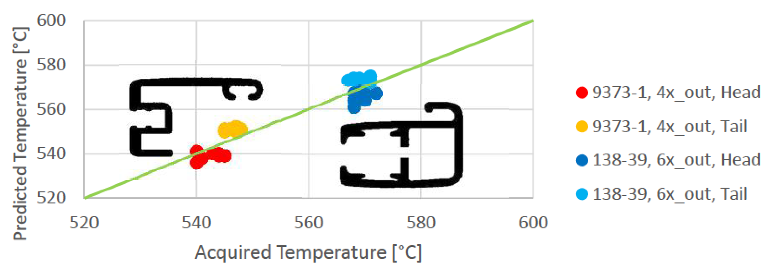
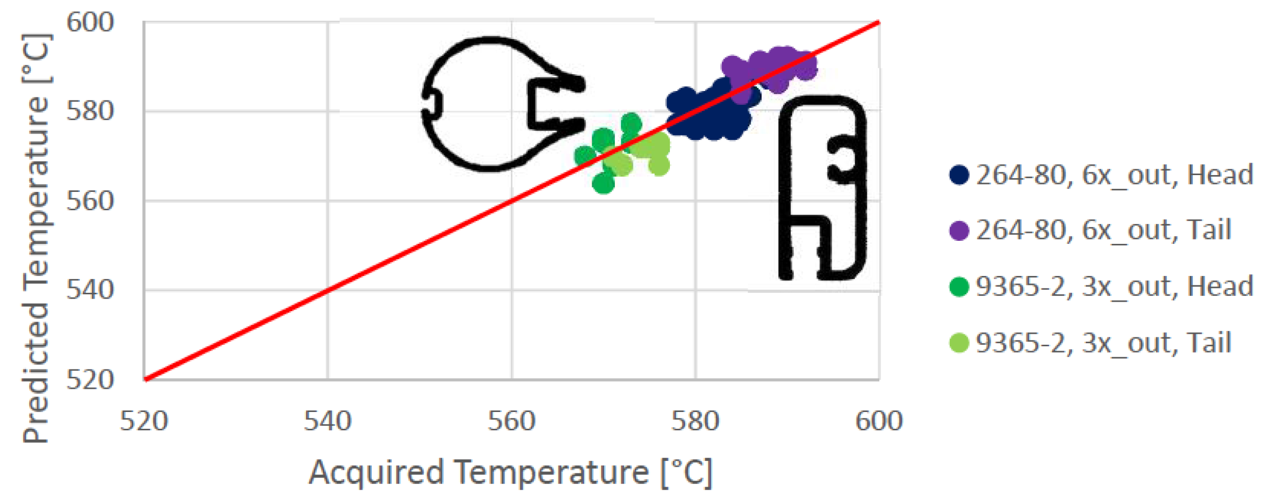
The algorithm with multiple profile represents the extrusion process better than the single one and for this reason only these results are reported. The goodness of the predicted temperatures was qualitatively defined by arranging them to the related experimental values inside a chart. The predicted and measured temperature for different profiles, solid and hollow, with more than one holes is reported in
Figure 1 and
Figure 2. The predicted temperature is in good agreement with the measured one in all the cases.
The multiple profile approach shows a great prediction capability: actually, all the prediction errors range among ±1.5%. As reference, the measurement accuracy of an industrial pyrometer is usually within ±1–2%. Using the algorithm with a single profile, all the predicted value are underestimated and the error is around 7%.
3.1. Analysis of Sensitivity
By means of a sensitivity analysis, the process variables influence on the profile head and tail temperatures were studied, measured in correspondence with the pyrometer measurement point.
The parameters outlined are:
vRAM, ram speed;
TIN, initial billet temperature. The billet was considered as homogeneously-heated;
TLINER, average liner temperature;
R, extrusion ratio.
The selected model involves three holes in the die.
The main result of these analyses refers to the container involvement into the definition of an isothermal extrusion condition (
Figure 3): actually, every extrusion parameter that affects the heating and the cooling phenomena between the billet and the liner has a critical value by means of which an isothermal extrusion can be achieved. Consequently, the heating and the cooling phenomena that take place downstream the container, i.e., the material-die interaction and the material environment interaction, cannot be accounted to get an isothermal extrusion, because they increase or decrease the whole material temperature in the same measure. Therefore, this condition is achieved only when at the end of the material-container interactions the billet tail temperature will be almost equal to the initial billet head temperature.
3.2. Billet Temperature Taper Definition
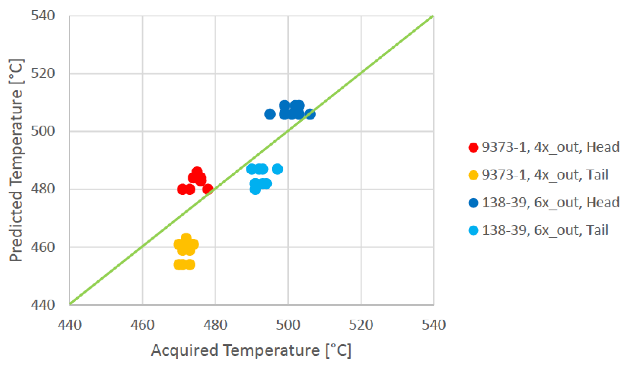
After the temperature increase trend related to a billet extrusion is defined by means of a proper model, the next step is focused on the determination of the billet temperature taper. It is essential when an isothermal extrusion condition must be reached without a variation of the extrusion process parameters. Moreover, the potential of this approach is the possibility to obtain an isothermal extrusion at the maximum extrusion speed allowed by the die design, thus increasing the productivity of the press.
The taper temperature is defined by a reiterative cycle: the inputs of this process are the profile initial extrusion temperatures, considering a homogenously-heated billet, and the desired isothermal target temperature. With respect to each curve development, the logic behind the cycle is to locally decrease the billet initial temperature where the predicted final temperature is higher than the target one, and vice versa. The process is iterative since every material temperature increase during the billet extrusion is a function of the mean equivalent flow stress that is non-linearly a function of the mean equivalent strain rate which again is non-linearly a function of the initial billet temperature. Given the previously examined profiles and known each process inputs, through the algorithm the temperature taper was estimated. The predicted values were related to the real ones (
Figure 4 and
Figure 5).
As results of the temperature taper estimation analysis, the algorithm overestimates the billet head temperature (⇨ +1.5%) and underestimates the tail one (⇨ −2%), thus the estimated taper is slightly steeper than the real one. However, considering the actual process errors, the ones related to the algorithm estimations can be reasonably accepted too.
4. Conclusions
The realized model (in particular the multi-hole one) is in good agreement with the real extrusion process that considers the actual die outlets. The error of the predicted extrusion temperature (or taper temperature) is less than the pyrometer accuracy. Moreover, the model is faster than an F.E.M. (finite element method) simulation guarantying a high on-site repeatability and it is translatable into the extrusion-press-controller software language.
Finally, the evidence that by adjusting some process variables, the isothermal extrusion can be achieved even without employing the related conventional practices was found: actually, a critical constant ram speed exists, as well as a homogeneous billet temperature and a liner temperature by means of which the extrusion is isothermal.
Author Contributions
Conceptualization, S.B. and A.G.; methodology, S.B., R.G. and G.M.; software development T.M. and R.G.; validation, S.B., A.G., R.G. and G.M.; writing—original draft preparation, S.B.; writing—review and editing, A.G. and R.G.; All authors have read and agreed to the published version of the manuscript.
Funding
Innodrivers-S3—Edition 2017, Misura A, Asse 1, Programma Operativo Regione Lombardia 2014-2020.
Acknowledgments
The authors thank Novellini SpA for the support in the test devoted to model validation.
Conflicts of Interest
The authors declare no conflict of interest.
References
- Ciuffini, A.F.; Di Cecca, C.; Barella, S.; Gruttadauria, A.; Merello, L.; Mapelli, C.; Mainetti, G.; Bertoletti, M. Influence of liquid nitrogen mold cooling on surface defects of aluminum alloys extruded semi-finished products. In Proceedings of the TMP 2016—5th International Conference on ThermoMechanical Processing, Milan, Italy, 26–28 October 2016. [Google Scholar]
- Peris, R.G. Effects of Extrusion Conditions on “Die Pick-Up” Formed during Extrusion of Aluminium Alloy AA6060. Master’s Thesis, AUT University Auckland, Auckland, New Zealand, 2007. [Google Scholar]
- Sheppard, T. Extrusion of Aluminium Alloys; Springer Science & Business Media: New York, NY, USA, 1999. [Google Scholar]
- Saha, P.K. Aluminum Extrusion Technology; ASM International: Materials Park, OH, USA, 2000. [Google Scholar]
- Lou, S.; Wang, Y.; Qin, S.; Xing, G.; Su, C. Influences of extrusion speed in hollow aluminium alloy profile extrusion. Aust. J. Mech. Eng. 2018, 16, 2–10. [Google Scholar] [CrossRef]
- Lela, B.; Musa, A.; Zovko, O. Model-based controlling of extrusion process. Int. J. Adv. Manuf. Technol. 2014, 74, 1267–1273. [Google Scholar] [CrossRef]
- Donati, L.; Segatori, A.; Reggiani, B.; Tomesani, L.; Bevilacqua Fazzini, P.A. Effect of liquid nitrogen die cooling on extrusion process conditions. Key Eng. Mater. 2012, 491, 215–222. [Google Scholar] [CrossRef]
- Ward, T.J.; Kelly, R.M.; Jones, G.A.; Heffron, J.F. The effects of nitrogen—Liquid and gaseous—On aluminum extrusion productivity. JOM 1984, 36, 29–33. [Google Scholar] [CrossRef]
- Ciuffini, A.F.; Barella, S.; Di Cecca, C.; Gruttadauria, A.; Mapelli, C.; Merello, L.; Mainetti, G.; Bertoletti, M. Surface Quality Improvement of AA6060 Aluminum Extruded Components through Liquid Nitrogen Mold Cooling. Metals 2018, 8, 409. [Google Scholar] [CrossRef]
- Holding, C. Recent experience in induction taper heating. Alum. Int. Today 2007, 19, 18. [Google Scholar]
- Abdul-Jawwad, A.K.; Bashir, A. A comprehensive model for predicting profile exit temperature of industrially extruded 6063 aluminum alloy. Mater. Manuf. Process. 2011, 26, 193–201. [Google Scholar] [CrossRef]
- Sheppard, T.; Raybould, D. On Load and Temperature Rise during the Extrusion of Superpure Al, Al-Zn, and Al-Zn-Mg Alloys. J. Inst. Met. 1973, 101, 33–44. [Google Scholar]
- Sheppard, T. Temperature changes occurring during extrusion of metals: Comparison of bulk, numerical, and integral profile predictions with experimental data. Mater. Sci. Technol. 1999, 15, 459–463. [Google Scholar] [CrossRef]
- Akeret, R. A numerical analysis of temperature distribution in extrusion. INST Met. J. 1967, 95, 204–211. [Google Scholar]
- Takahashi, M.; Yoneyama, T. Isothermal Extrusion of Aluminum Alloys (1st Part). Alum. ITS Alloy 2004, 16, 84–93. [Google Scholar]
- Prasad, Y.; Rao, K.P.; Sasidhar, S. Hot Working Guide: A Compendium of Processing Maps; ASM International: Metals Park, OH, USA, 2015. [Google Scholar]
- Celani, P.; Bertoletti, M.; Mainetti, E.; Ferrentino, A.; Seclì, C. Considerations about heat elimination from extrusion dies by using liquid nitrogen, extrusion speed increase and surface defects elimination, metallurgic structure modification and extrusion process simulation. In Proceedings of the Aluminium 2000 world Congress, Milan, Italy, 14–18 May 2013. [Google Scholar]
| Publisher’s Note: MDPI stays neutral with regard to jurisdictional claims in published maps and institutional affiliations. |
© 2021 by the authors. Licensee MDPI, Basel, Switzerland. This article is an open access article distributed under the terms and conditions of the Creative Commons Attribution (CC BY) license (https://creativecommons.org/licenses/by/4.0/).


 ,
, 