Abstract
The rapid evolution of materials and manufacturing processes, driven by global competition and new safety and environmental regulations has had an impact on automotive structures (Body In White; BIW) manufacturing. The need for lighter vehicles, with more equipment, that are safer and eco-friendly at the same time, relates to the entire life cycle of the car. Car and steelmakers agree that weight reduction is possible, and the solution involves the use of new advanced high-strength steels. Thinner and stronger materials lead to higher demands on stamping, the most used manufacturing in BIW parts. The use of advanced high-strength steels raises new challenges, especially concerning the lubrication between the die and the sheet. To study the lubrication conditions of the stamping process, a sheet metal forming a simulator was developed. The simulator consists of two cylinders that pull the strip of steel and a pin in between. The angle between the cylinders can be adjusted from 0 to 90 degrees, which allows analysis of the effect of the stamping angle. The pull force and velocity can be set and measured, and the peripheric pin velocity, the strain, and the strain velocity can be measured as well. In this work, the tribological properties of Dual-Phase 600 stainless steel using different processing conditions have been analyzed. To this end, a factorial experiments design with twelve parameters that compare the behavior of different angles and diameters was run. The results showed that the friction coefficient increases by increasing the bending angle and decreases with pin diameter.
1. Introduction
The structure of the car is known by the acronym BIW (Body in White) and consists of multiple parts, mainly advanced high-strength steels.
In recent decades, life cycle analysis of automobiles has been a basic tool in decision making. An initiative around this idea was developed by WorldAutoSteel (a grouping of 20 of the largest manufacturers. One of these organizations, the Steel Market Development Institute (SMDI), developed the Future Steel Vehicle (FSV) project.
The objective of this project is to reduce the mass of the load-bearing structure by 35%, compared to a reference vehicle. As well as the total reduction of emissions, during the total life cycle of the vehicle, by up to 70%. This would be met in conjunction with a list of requirements related to impact performance and durability, allowing five stars in safety parameters (ratios).
Currently, in order to reduce the thickness of the different metallic components found in cars, such as uprights, sills, side reinforcements, etc. (and with an increase in impact resistance), so-called advanced high strength steels (AHSSs) are beginning to be used.
Steels for chassis parts with high liability are defined as HSS (high-strength steels) with yield strength between 210 and 550 MPa and an ultimate stress between 270 and 700 MPa.
Steels with yield strengths greater than 550 MPa and with ultimate stresses greater than 700 MPa are called advanced high strength steels (AHSSs).
Figure 1 shows a classification of the advanced steels currently used for BIW fabrication.
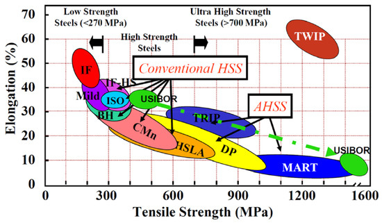
Figure 1.
Current supply of steels for BIW (Body in White).
AHSSs comprise the families of transformation-induced plasticity (TRIP) steels, martensitic (MART) steels, and dual-phase (DP) steels.
DP steels consist of a ferritic matrix phase and a dispersed phase formed by hard martensite islands. Increasing the proportion of the hard phase generally increases strength.
Regarding the manufacturing process, about 75% of the steel parts (by weight) of the vehicle are manufactured by the stamping process. The quality of sheet metal formation is often determined by the friction in the contact between the part and the die. If the frictional forces of the interface are excessively high, the local deformation conditions and the formability of the part may be impaired. In addition, the energy required for the process can become extremely high [1].
The magnitude of friction can be evaluated as a value of the shear strength of the interlayer. Friction, either because of its usefulness in controlling creep, deformation and recovery, or its adverse aspect of excessive loads, has a central role in sheet metal formation [2]. The deformation process, tool design, surface quality, lubricant selection and failure prediction through simulation are highly dependent on the knowledge of the friction mechanism [3,4]. Friction is not an independent parameter, but depends on several variables such as surface roughness, lubricant, surface chemistry, relative sliding velocity, temperature and forming pressure [5]. The shear friction force on the contact surface can be modified by lubrication as well as by altering the surface roughness for workpiece and tool.
In many metal forming processes, low friction can be beneficial. It reduces the pressure on the contact surface, the resulting forming force, the process energy required and the heat produced. However, in the sheet forming and rolling process, friction can be desirable and even essential to ensure proper clamping, surface contact and plastic deformation during processing [6]. On the other hand, a careful design of the lubrication system to achieve an adequate friction level is essential for sheet metal forming as mentioned by Wilson [7]. This, however, can be a difficult, since different lubrication regimes are possible simultaneously at the blade–tool interface [3].
The objective of this work is to determine the influence of bending angle and radius of curvature on the coefficient of friction for DP600 stainless steel during the metal forming process.
2. Materials and Methods
The determination of the coefficient of friction during the metal forming process was performed using a bending under tension test (BUT) simulator, as shown in Figure 2 and Figure 3. In this simulator the strip is stretched from each end at speeds and , resulting in the measurement of forces and .
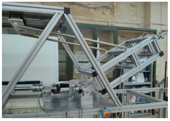
Figure 2.
Metal forming simulator detail.
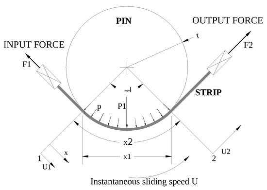
Figure 3.
Bending under tension (BUT) operating diagram.
The actuators used to stretch the strip were two Thomson ball screws, model T09-B2505MN050-13 (Thomson Linear, BideFord, Devon, United Kingdom), with a maximum dynamic load of 10,000 N, maximum displacement speed of 0.3 m/s, maximum input speed 4000 rev/min, repeatability of ±0.05 mm, and maximum radial dynamic load of 300 N.
The sensors in charge of force measurement were two HBM U3/20 kN load cells of class 0.2 accuracy, with a linearity of less than 0.2%, capable of measuring both tension and compression.
The sensors in charge of measuring the displacement of the ends of the sheet were two ELAP optical strips, model PD500360LP1 (Thomson Linear, BideFord, Devon, United Kingdom), with a maximum resolution of 0.005 mm (by electronic quadruplication) and a grid accuracy of ±3 μm/m.
The element simulating the forming tool (pin) was a cylinder of at least 15 mm (constructional restriction imposed by the designers). In this case, it is a 16 mm cylinder made of steel according to EN 10 027-2 No. 1.2379, with symbolic designation X153CrMoV12, hardened to a hardness of 60 HRc, and with an N5 ground finish.
Data acquisition was performed using HBM’s QuantumX MX840 DAQ using an acquisition frequency of 100 Hz.
The material tested was a Dual Phase 600 (DP600) steel manufactured by Arcelor Mittal, Chicago, USA. The material was tensile tested at different speeds in order to determine the possible dependence of the test results on speed. The results are shown in Table 1. As can be seen, the variation in mechanical performance is not significant.

Table 1.
DP600 tensile test results.
Figure 4 shows the dimensions of the specimens used during the tests at the BUT. The thickness of the specimens was 1.5 mm.
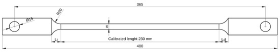
Figure 4.
Specimen dimensions.
The coefficient of friction was calculated according to the equations of Saha [8], Equation (1); Fox [9], Equation (2); and Han [10], Equation (4).
where and are the input and output forces, respectively, and is the angle of contact.
where is the bending force of the sheet obtained from a test where the pin rotates freely by means of Equation (3).
where and are the measured forces when the pin is freely rotating.
where D is the pin diameter and t is the foil thickness.
3. Results
After carrying out the experiments under the conditions detailed in the previous section, the following results were obtained. Figure 5 and Figure 6 show the velocity and force measurements made during a test. As can be seen, these measurements are not initially stable due to the prestressing effect of the strip. The data taken for the friction coefficient calculation correspond to the beginning of the stable period.
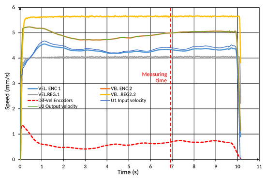
Figure 5.
Test velocity measurements.
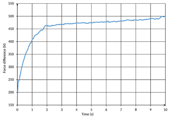
Figure 6.
Force difference () measurement.
Figure 7 shows the determination of the coefficient of friction for different angles and a diameter of 16 mm, according to Equations (1), (2), and (4). On the other hand, Figure 8 shows the influence of the pin diameter for a 60-degree angle, according to Equation (4).
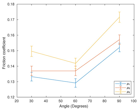
Figure 7.
Friction coefficient vs. angle.
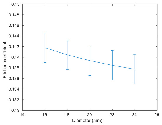
Figure 8.
Friction coefficient vs. diameter.
4. Conclusions
From the analysis of the results obtained, it can be concluded that of the parameters analyzed, the angle plays a more important role in the friction coefficient during sheet metal forming. This relationship is neither linear nor proportional since, for intermediate angles between 30 and 90 degrees, lower friction values are obtained, and the use of intermediate angles is preferable over the 30 or 90 degrees.
On the other hand, the diameter value also plays an inversely proportional factor in the friction coefficient, although in a significantly smaller way.
Finally, it should be noted that the three equations used in the calculation of the proportional friction coefficient have similar values, with a variation of results around 10%. As can be seen in Figure 7, the friction coefficient values increase as the equations consider a higher number of process parameters (e.g., bending force and pin diameter), thus getting closer to the real phenomenon. Of all of them, the most complete equation is Han’s, providing values of the friction coefficient between 0.142 and 0.172.
Author Contributions
All authors contributed equally to write this manuscript. All authors have read and agreed to the published version of the manuscript.
Funding
This research received no external funding.
Conflicts of Interest
The authors declare no conflict of interest.
References
- Lovell, M.; Deng, Z. Characterization of interfacial friction in coated sheet steels: influence of stamping process parameters and wear mechanisms. Tribol. Int. 2002, 35, 85–95. [Google Scholar] [CrossRef]
- Fratini, L.; Lo Casto, S.; Lo Valvo, E. A technical note on an experimental device to measure friction coefficient in sheet metal forming. J. Mater. Process. Technol. 2006, 172, 16–21. [Google Scholar] [CrossRef]
- Shih, H.C.; Wilson, W.R.D. Effects of Contact Pressure and Strain on Friction in Sheet-Metal Forming. Tribol. Trans. 1999, 42, 144–151. [Google Scholar] [CrossRef]
- Wiklund, D.; Rosén, B.G.; Gunnarsson, L. Frictional mechanisms in mixed lubricated regime in steel sheet metal forming. Wear 2008, 264, 474–479. [Google Scholar] [CrossRef]
- Joun, M.; Moon, H.; Choi, I.; Lee, M.; Jun, B. Effects of friction laws on metal forming processes. Tribol. Int. 2009, 42, 311–319. [Google Scholar] [CrossRef]
- Kosanov, J.; Lenard, J.; Uhrig, J.; Wallfarth, B. The effect of lubricant additives on the coefficient of friction in the flat-die test. Mater. Sci. Eng. A 2006, 427, 274–281. [Google Scholar] [CrossRef]
- Wilson, W.; Kokoska, E. The influence of lubricant composition on the lubricant breakdown in upsetting between overhanging dies. Wear 1975, 32, 25–32. [Google Scholar] [CrossRef]
- Saha, P.K.; Wilson, W.R. Influence of plastic strain on friction in sheet metal forming. Wear 1994, 172, 167–173. [Google Scholar] [CrossRef]
- Fox, R.T.; Maniatty, A.M.; Lee, D. Determination of friction coefficient for sheet materials under stretch-forming conditions. Metall. Trans. A 1989, 20, 2179. [Google Scholar] [CrossRef]
- Han, S. The influence of tool geometry on friction behavior in sheet metal forming. J. Mater. Process. Technol. 1997, 63, 129–133. [Google Scholar] [CrossRef]
Publisher’s Note: MDPI stays neutral with regard to jurisdictional claims in published maps and institutional affiliations. |
© 2021 by the authors. Licensee MDPI, Basel, Switzerland. This article is an open access article distributed under the terms and conditions of the Creative Commons Attribution (CC BY) license (https://creativecommons.org/licenses/by/4.0/).