Proceeding Paper

Resonant Mode Coupling Method for the Description of Oscillating Dipoles Emission inside Stacked Photonic Nanostructures †

Skolkovo Institute of Science and Technology, Nobel Street 3, Moscow 143025, Russia
*
Author to whom correspondence should be addressed.
Presented at the 2nd International Online-Conference on Nanomaterials, 15–30 November 2020; Available online: https://iocn2020.sciforum.net/.
Mater. Proc. 2021, 4(1), 34; https://doi.org/10.3390/IOCN2020-07928
Published: 11 November 2020
(This article belongs to the Proceedings of The 2nd International Online-Conference on Nanomaterials)

Abstract

:
Resonant modes are important characteristics of the optical properties of photonic crystals since they are responsible for the features in the transmission and reflection spectra as well as the emissivity of quantum emitters inside such structures. We present a resonant modes expansion method applied to a problem of radiating dipoles inside a photonic crystal. In stacked photonic crystal slabs, there is a coupling between the resonances of distinct subsystems and Fabry–Perot resonances. We propose a technique to calculate the coefficients of resonant mode expansion based on the scattering matrix formalism of the Fourier modal method (FMM). The method appears to be convenient since it does not require rigorous normalization of resonant fields or application of perfectly matched layers. Then, we demonstrate the agreement between the resonant modes expansion results and exact FMM solutions.

Published: 11 November 2020

1. Introduction

Resonant modes are intrinsic properties of an electromagnetic structure that are of significant interest in modern electrodynamics and optics due to a great variety of potential applications. Resonances determine light-matter interaction, scattering properties of a structure, emission properties, optical activity, and many others [1]. Such modes are defined as nonzero solutions of Maxwell’s equations without any electromagnetic wave sources. For open systems with losses, resonant energies have a nonzero negative imaginary part. It has been shown previously [2,3,4] that resonant field distributions and resonant mode expansion coefficients could be obtained using an iterative scattering matrix pole search method. Nevertheless, this method was not applied to the problem of electromagnetic waves emission for dipoles inside photonic stacked systems. An ability to provide a resonant modes expansion for such a problem allows one to find positions inside a photonic system in which a dipole can excite a resonance in the most effective way. Once the resonances of the lower and upper parts are known, it is very convenient to calculate the scattering and radiation emission matrices of the stacked system in a sufficient energy range without direct Fourier modal method (FMM) application. This can highly increase the calculation speed so one can choose any desired energy mesh step size for the resolution of the narrowest peculiarities of spectral data. Moreover, such combined system consideration gives an additional comprehension of how subsystem resonance couples to produce the resonances of the whole system. This could also lead to a better-arranged photonic system design because coupled and uncoupled resonances are responsible for strong optical effects such as the transmission of radiation asymmetry, a modulated quality factor, etc. As was shown in paper [5], dipole approximation is an effective tool for the description of small plasmonic particles, which cannot be adequately included in the FMM calculation without a prohibitively large number of Fourier harmonics included. Thus, the resonant mode expansion application to a dipole emission can make a significant contribution to a variety of optical and electromagnetic problems. This article aims to present such an approach based on the direct resonant expansion of the scattering matrix and therefore does not employ normalization of divergent resonant fields [1,6,7].

2. Methods

Let us consider a metal-dielectric structure consisting of two parts, A and B, that are periodic in x and y directions. It is necessary to determine the amplitude of the outward radiation created by dipoles harmonically oscillating in a thin layer between parts A and B. In case one already knows the scattering matrices of the upper and lower subsystems (Sa and Sb, respectively), it is enough to set the input amplitudes equal to zero, calculate the field discontinuities near the plane of the dipoles according to Maxwell equations, and add the condition for maintaining the amplitude in a closed passage inside the structure. Then, the relation between the vector of amplitude discontinuities near the dipole plane and outgoing wave amplitudes is [8,9] (see Figure 1 for details and wave amplitudes notation)
( | d 2 + | u 2 ) = B out   ( | j d | j u )
Here, the radiation emission matrix Bout is constructed from sub-blocks of scattering matrices:
B out = ( S d d b D 1 S d d b D 1 S d u a S u u a D 2 S u d b S u u a D 2 ) = ( S d d a + b ( S d d a ) 1 ( S d u a + b S d u b ) ( S u u b ) 1 ( S u d a + b S u d a ) ( S d d a ) 1 S u u a + b ( S u u b ) 1 ) .
We use the following notation:
D 1 = ( 1 S d u a S u d b ) 1 D 2 = ( 1 S u d b S d u a ) 1
Although this is the full answer, it does not provide any information about the resonances and coefficients of their excitation. For the derivation of coupled resonant modes, one should apply the standard technique to calculate the resonances of the upper and lower subsystems separately [3,4]. The scattering matrices of these systems break into a nonresonant slowly varying part and sum over resonant contributions:
( | d 2 + | u 1 ) = [ ( S ˜ d d a S ˜ d u a S ˜ u d a S ˜ u u a ) + n = 1 N | O n a 1 ω ω n a I n a | ] ( | d 1 | u 2 + ) ,
( | d 3 | u 2 ) = [ ( S ˜ d d b S ˜ d u b S ˜ u d b S ˜ u u b ) + n = 1 M | O n b 1 ω ω n b I n b | ] ( | d 2 | u 3 ) .  
There are no incoming waves, so we should put d1, u3 = 0. Using notation α-n and β+n for the coefficients of the resonant modes excitation of the subsystems, we obtain the equation
( 1 S d u a S u d b 1 ) ( d 2 + u 2 ) = n ( α n | O d , n a β n + | O u , n b ) + ( j d j u )
We also need to include the Fabry–Perot modes in the coupling model, which could be found from the following equation [10]:
M ( | d 2 + | u 2 ) = ( 1 S ˜ d u a S ˜ u d b 1 ) ( | d 2 + | u 2 ) = 0
This equation has a simple physical meaning. The Fabry–Perot modes of an open system are governed by nonresonant reflections of the upper and lower subsystems. Thus such modes should have complex energies to maintain the wave amplitudes after a circular passage inside the whole structure in the presence of no electromagnetic wave sources. To derive the poles of the inverse matrix M−1, one should apply the same procedure as for the resonant expansion of the S-matrix:
M 1 = N ˜ + n | O n F P I n FP | ω ω n FP
Finally, by combining equations (6) and (8) we can derive the coupled resonances and expansion coefficients that describe how the new resonant modes of the whole system are formed from the modes of the subsystems.

3. Results

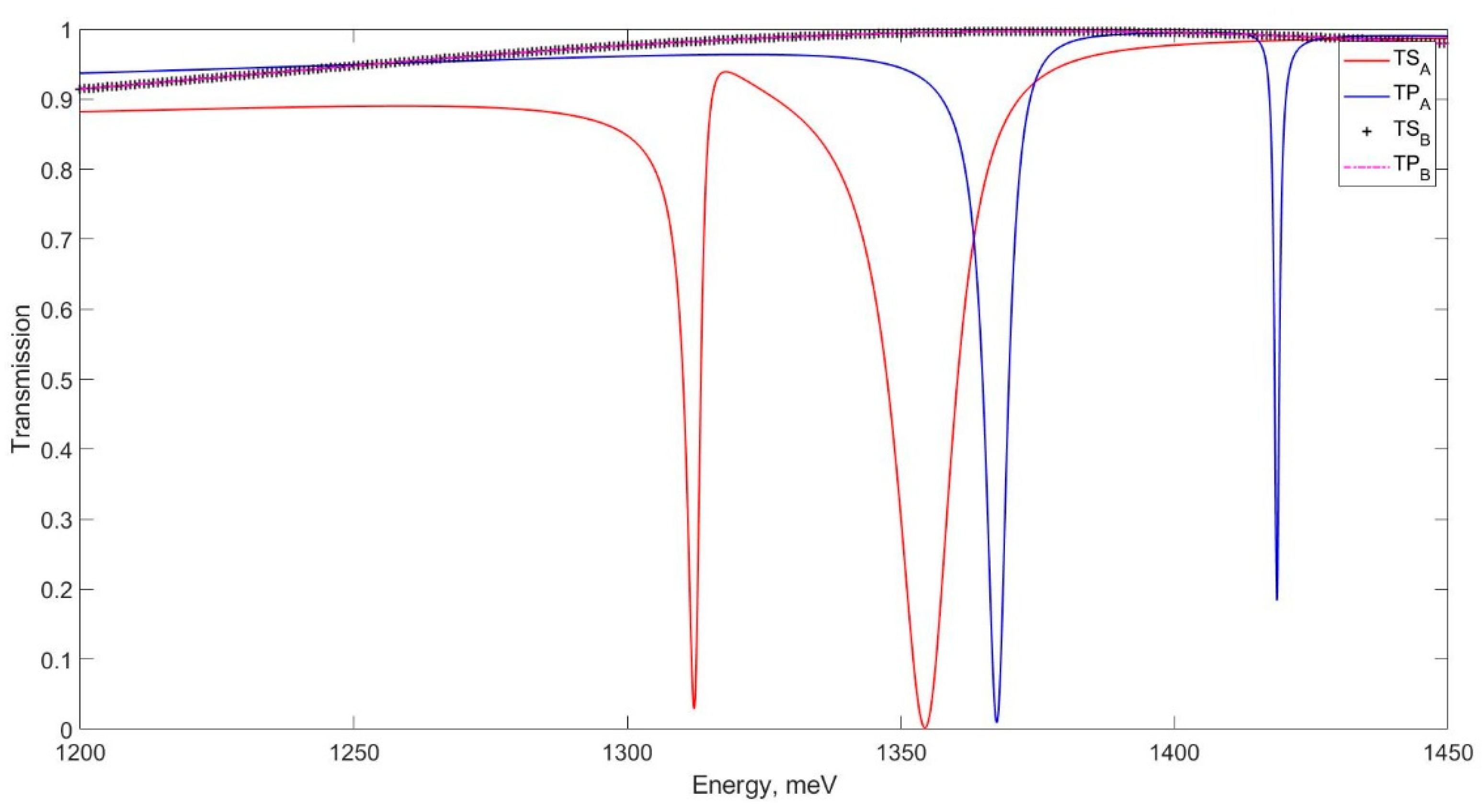
For validation purposes, we decided to calculate an emission of a dipole source from the coupled system of a simple waveguide on the bottom and a waveguide with a 1D grating corrugation on the top (Figure 1). The structure has the following properties: both waveguides and the grating are made of an isotropic material with a permittivity chosen to be ε = 2.25 + 0.001i; thus, it is quite close to a crone glass or SiO2 permittivity in a near-infrared range. The grating period is p = 0.7 μm, the width of the grating slits is a = 0.3 μm, and the grating thickness and the thickness of the upper waveguide are hgr = h(top)wg = 0.3 μm. The lower waveguide has a thickness twice as large as the upper one h(bot)wg = 0.6 μm. Two waveguides are separated by an air gap, and the whole structure is also surrounded by air. The dipoles are located in the middle between the upper and lower waveguides at a distance of 100 nm from them. We have calculated the transmission spectra in the energy range of 1200–1450 meV with the conventional FMM; the results are shown in Figure 2.
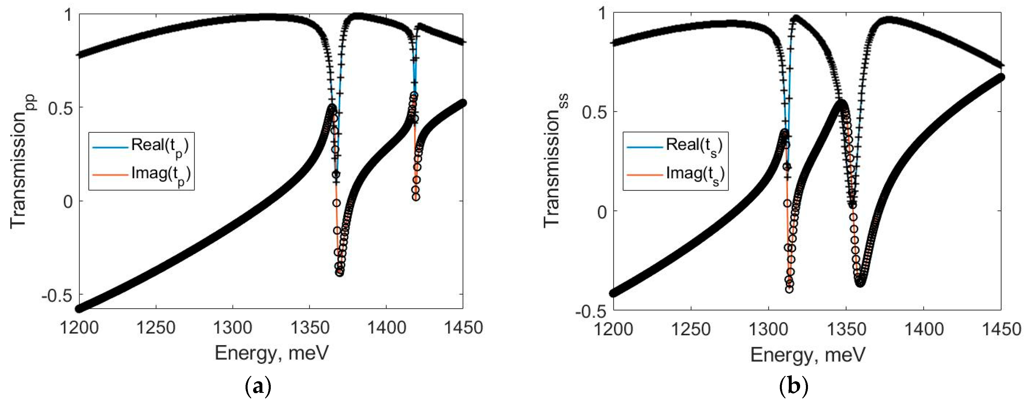
As the upper and lower structures are only different by the periodic corrugation, one can see how this periodicity changes the transmission spectrum of a waveguide and superimposes well-pronounced dips. Then, we calculate the poles of the scattering matrices of these two structures using the previously described technique and retrieve the transmission using the resonant modes expansion. For s- and p-polarized plane waves, the retrieval results are presented in Figure 2.
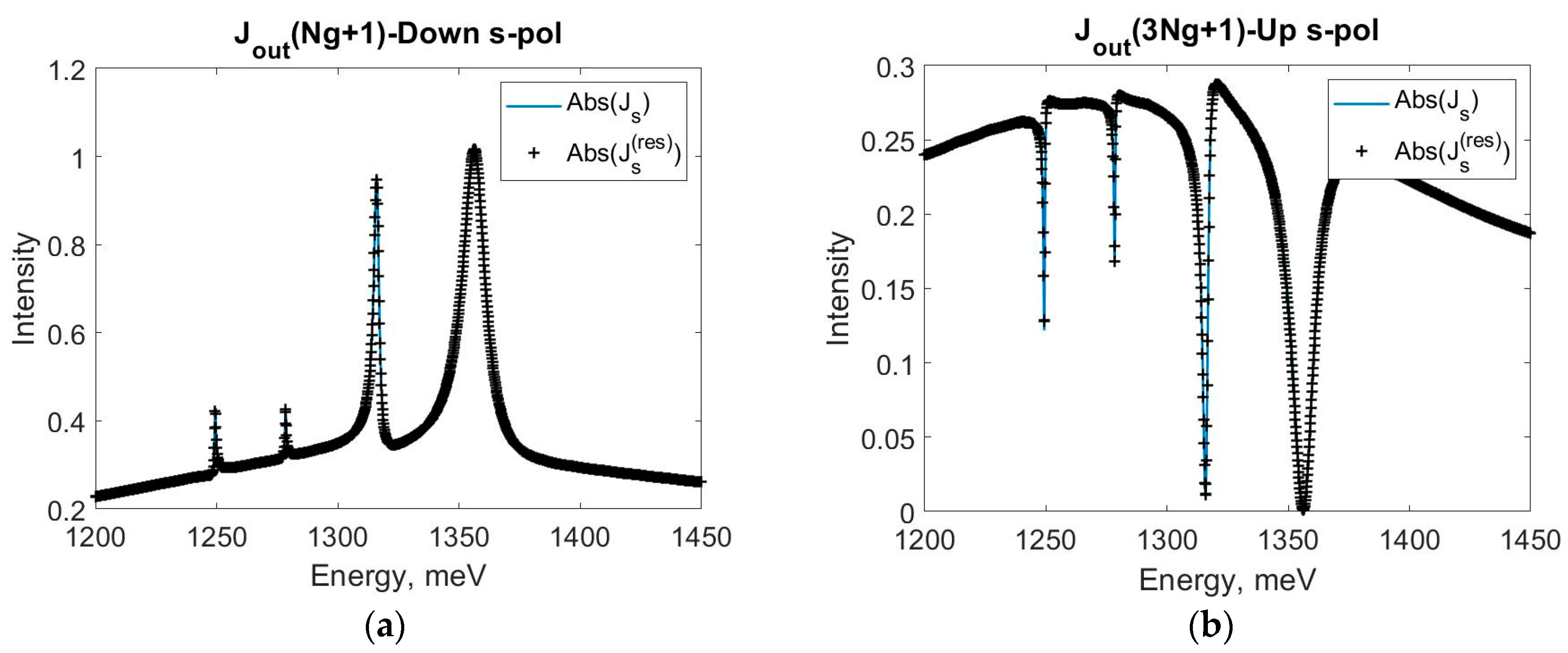
Finally, we derive Fabry–Perot resonances and calculate the dipole emission in the main optical channel using the resonance coupling method. We also compare these results to the emission spectra calculated simply using the Bout matrix. One can find quite a satisfying agreement in Figure 3.

4. Discussion

We have shown that the coupling resonance method is an effective tool for the derivation of optical modes that are combinations of the separated subsystem resonances and Fabry–Perot resonances. Good convergence with the traditional FMM has been observed. One can confidently use this method to resolve narrow spectral peculiarities with a sufficiently small computational effort, once the resonances of the subsystems and Fabry–Perot resonances are known. Moreover, this method does not require normalization of modes due to the natural dyadic form presented in our approach.

Author Contributions

Conceptualization, N.G.; methodology, N.G.; software, D.G.; validation, N.G., S.D., and I.F.; formal analysis, D.G.; investigation, D.G.; resources, D.G.; data curation, D.G.; writing—original draft preparation, D.G.; writing—review and editing, N.G., S.D., and I.F.; visualization, D.G.; supervision, N.G., S.D.; project administration, N.G.; funding acquisition, N.G., S.D. All authors have read and agreed to the published version of the manuscript.

Funding

This work was funded by the Russian Foundation for Basic Research (Grant No. 18-29-20032).

Conflicts of Interest

The authors declare no conflict of interest. The funders had no role in the design of the study; in the collection, analyses, or interpretation of data; in the writing of the manuscript, or in the decision to publish the results.

References

  1. Lalanne, P.; Yan, W.; Vynck, K.; Sauvan, C.; Hugonin, J. Light interaction with photonic and plasmonic resonances. Laser Photonics Rev. 2018, 12, 1700113. [Google Scholar] [CrossRef]
  2. Tikhodeev, S.; Yablonskii, A.; Muljarov, E.; Gippius, N.; Ishihara, T. Quasiguided modes and optical properties of photonic crystal slabs. Phys. Rev. B 2002, 66, 045102. [Google Scholar] [CrossRef]
  3. Gippius, N.; Tikhodeev, S.; Ishihara, T. Optical properties of photonic crystal slabs with an asymmetrical unit cell. Phys. Rev. B 2005, 72, 045138. [Google Scholar] [CrossRef]
  4. Gippius, N.; Weiss, T.; Tikhodeev, S.; Giessen, H. Resonant mode coupling of optical resonances in stacked nanostructures. Opt. Express 2010, 18, 7569–7574. [Google Scholar] [CrossRef] [PubMed]
  5. Fradkin, I.; Dyakov, S.; Gippius, N. Fourier modal method for the description of nanoparticle lattices in the dipole approximation. Phys. Rev. B 2019, 99, 075310. [Google Scholar] [CrossRef]
  6. Muljarov, E.; Langbein, W.; Zimmermann, R. Brillouin-Wigner perturbation theory in open electromagnetic systems. Europhys. Lett. 2010, 92, 50010. [Google Scholar] [CrossRef]
  7. Weiss, T.; Schäferling, M.; Giessen, H.; Gippius, N.; Tikhodeev, S.; Langbein, W.; Muljarov, E. Analytical normalization of resonant states in photonic crystal slabs and periodic arrays of nanoantennas at oblique incidence. Phys. Rev. B 2017, 96, 045129. [Google Scholar] [CrossRef]
  8. Whittaker, D.; Culshaw, I. Scattering-matrix treatment of patterned multilayer photonic structures. Phys. Rev. B 1999, 60, 2610–2618. [Google Scholar] [CrossRef]
  9. Lobanov, S.; Weiss, T.; Dregely, D.; Giessen, H.; Gippius, N.; Tikhodeev, S. Emission properties of an oscillating point dipole from a gold Yagi-Uda nanoantenna array. Phys. Rev. B 2012, 85, 155137. [Google Scholar] [CrossRef]
  10. Weiss, T.; Gippius, N.; Granet, G.; Tikhodeev, S.; Taubert, R.; Fu, L.; Schweizer, H.; Giessen, H. Strong Resonant mode coupling of Fabry–Perot and grating resonances in stacked two-layer systems. Photonics Nanostruct. Fundam. Appl. 2011, 9, 390–397. [Google Scholar] [CrossRef]
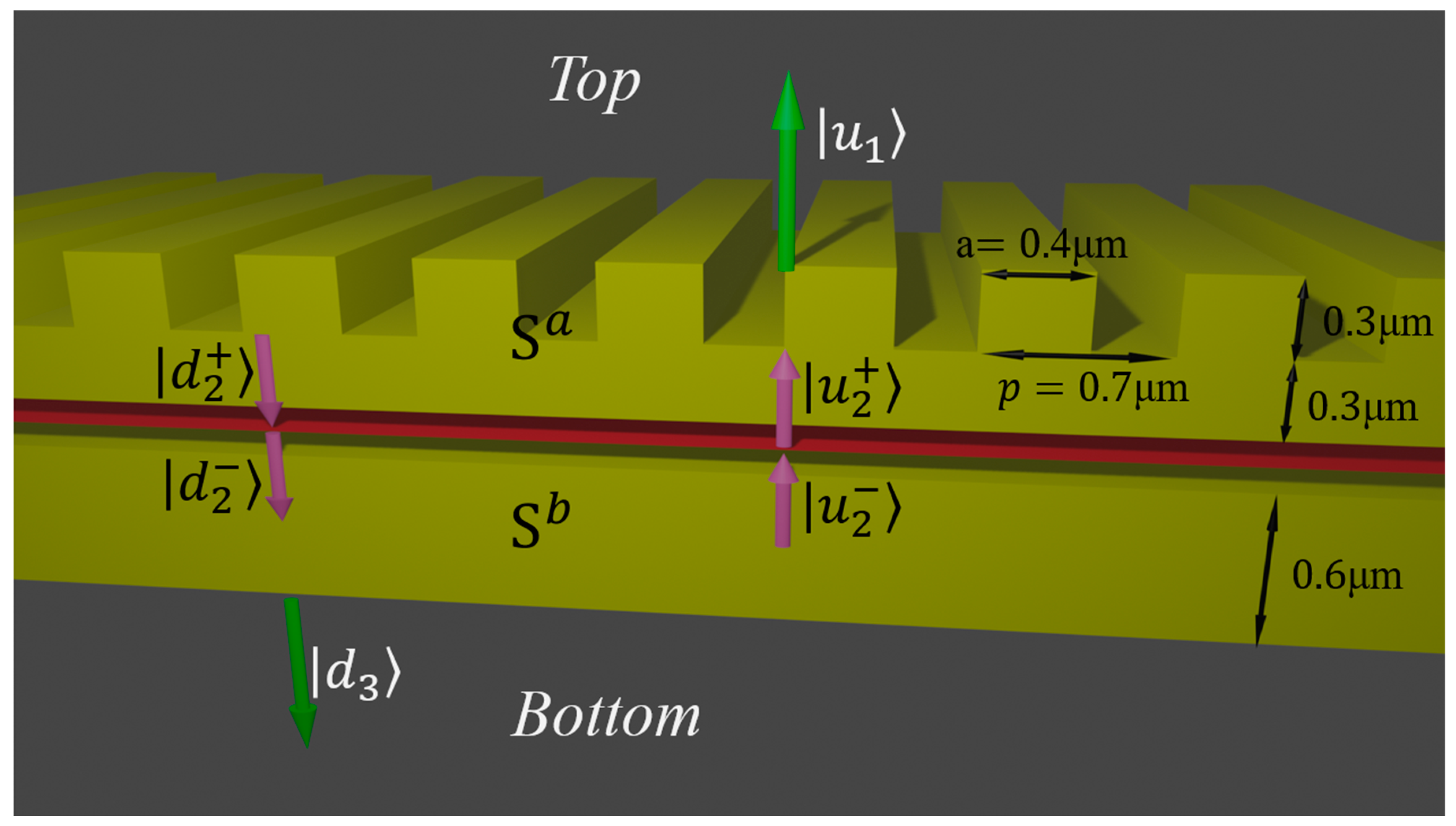
Figure 1. Schematic description of the system under consideration. The system is divided into upper A and lower B subsystems by the red layer denoting the plane of dipole emitters. The optical properties of the subsystems are described by the scattering matrices Sa and Sb. The upper structure is a waveguide with a 1D grating on the top of it and an air gap of thickness 100 nm on the bottom, while the lower structure is a waveguide with a 100 nm thick air gap on the top. Amplitudes of the Fourier harmonics are identified as d and u for waves propagating from top to bottom and backward, respectively; subscripts 1, 2, and 3 correspond to the amplitudes right above the upper surface of the whole structure, near the dipoles, and right under the lower surface. Due to the presence of the dipoles, the magnetic field must be discontinuous and so the wave amplitudes directly above and under the emitters are designated with + and − in the superscript.
Materproc 04 00034 g001
Figure 2. Transmission spectra of the upper A (a waveguide and grating surrounded by air) and lower B (a single waveguide in the air) structures calculated with the conventional Fourier modal method (FMM). Red and blue solid lines correspond to transmission from top to bottom of s- and p-polarized electromagnetic plane waves in the structure A, while black crosses and the magenta dotted line correspond to transmission from top to bottom in the structure B in s- and p-polarization.
Materproc 04 00034 g002
Figure 3. Real (red solid lines) and imaginary (blue solid lines) parts of the top to bottom transmission in the A subsystem calculated with the conventional FMM and using the resonant modes expansion (black crosses and circles) for (a) p-polarized, (b) s-polarized plane waves.
Materproc 04 00034 g003
Figure 4. Calculated spectra of the emission in the main channel with s-polarization in (a) top and (b) bottom directions of the oscillating dipole sources. For simplicity, the source is taken to be a plane with uniform current density polarized in the same plane at an angle of 45 degrees to the slits of the grating. Solid blue lines correspond to the results obtained with the conventional FMM; black crosses correspond to the coupled resonant modes approach. The intensity is normalized to the maximum radiation intensity of an equivalent harmonically oscillation current source (with the same magnitude and the same frequency) in free space.
Materproc 04 00034 g004
Publisher’s Note: MDPI stays neutral with regard to jurisdictional claims in published maps and institutional affiliations.