Proceeding Paper

Numerical Modelling of Structural Behaviour of Curved Insulating Glass Units †

Department of Structural Engineering, Silesian University of Technology, Akademicka 5, 44-100 Gliwice, Poland
*
Author to whom correspondence should be addressed.
Presented at the 10th MATBUD’2023 Scientific-Technical Conference “Building Materials Engineering and Innovative Sustainable Materials”, Cracow, Poland, 19–21 April 2023.
Mater. Proc. 2023, 13(1), 12; https://doi.org/10.3390/materproc2023013012
Published: 14 February 2023
(This article belongs to the Proceedings of 10th MATBUD’2023 Scientific-Technical Conference)

Abstract

:
The application of curved Insulating Glass Units (IGUs) in facades has emerged as a novel solution to meet aesthetic and energy performance objectives. Due to improved stiffness, curved IGUs cannot equalise internal and atmospheric pressure changes by pillowing, as flat IGUs do. Thus, the climatic loads in curved IGUs may be several times higher than those in flat units. This paper deals with experiments and numerical simulations of cylindrically curved IGUs. It presents the results of an experimental campaign designed to collect data that validate the numerical model of a curved IGU developed within this study. The model is sequentially used to analyse a case study that compares the resulting internal pressure, displacement, and stress in glass in a flat and curved IGU subjected to the characteristic climatic actions given by DIN18008-1.

1. Introduction

The application of curved Insulating Glass Units (IGUs) in facades has emerged as a novel solution to meet aesthetic and energy performance objectives [1]. The increased stiffness resulting from curvature has been identified as a remarkable advantage over flat glass, decreasing support requirements and improving the aesthetics or increasing spans. However, there are many constraints regarding its design, production, and performance during operation [2]. In general, as the temperature of the gas entrapped in the IGU’s gap changes its value, the gas volume inside varies relative to its original volume. The bending stiffness of the component panes limits their deformations (pillowing effect of the panes) and causes a change in the pressure of the gas inside the IGU gap. Changes in internal pressure result in unfavourable visual effects that can be observed as distorted images reflected in windows. Due to improved stiffness, curved IGUs cannot equalise internal and atmospheric pressure changes by pillowing, as flat IGUs do. Therefore, the climatic loads in curved IGUs can be several times higher compared to flat units, leading to glass fracture or failure of the silicone seal, particularly in combination with mechanical stresses [3].
Although research that focuses on the performance of flat IGUs under climatic loads has been presented in many studies, research on curved IGUs is still limited. Some results from numerical studies have been reported, but there are practically no experimental studies. Nizich et al. [4] proved numerically that the equalisation rate of the curved IGU is significantly reduced compared to a flat unit. Furthermore, it was found that the curvature and resulting increased internal pressure require increasing the horizontal bite of the seal several times. In the paper by Bao and Gregson [5], a thorough sensitivity study on the internal pressure of cylindrically curved IGUs was presented, considering a series of geometric variables. The main finding was that, given the same climatic action and for the same dimension, curved IGUs always generate significantly higher internal pressure than flat IGUs.
This paper deals with experiments and numerical simulations of cylindrically curved IGUs. It presents the results of an experimental campaign designed to collect data that validate a numerical model of curved IGU developed within this study. The validated model is sequentially used to analyse a case study comparing the resulting internal pressure and other static quantities in flat and curved IGUs subjected to characteristic climatic actions given by DIN18008-1 [6].

2. Research Methodology
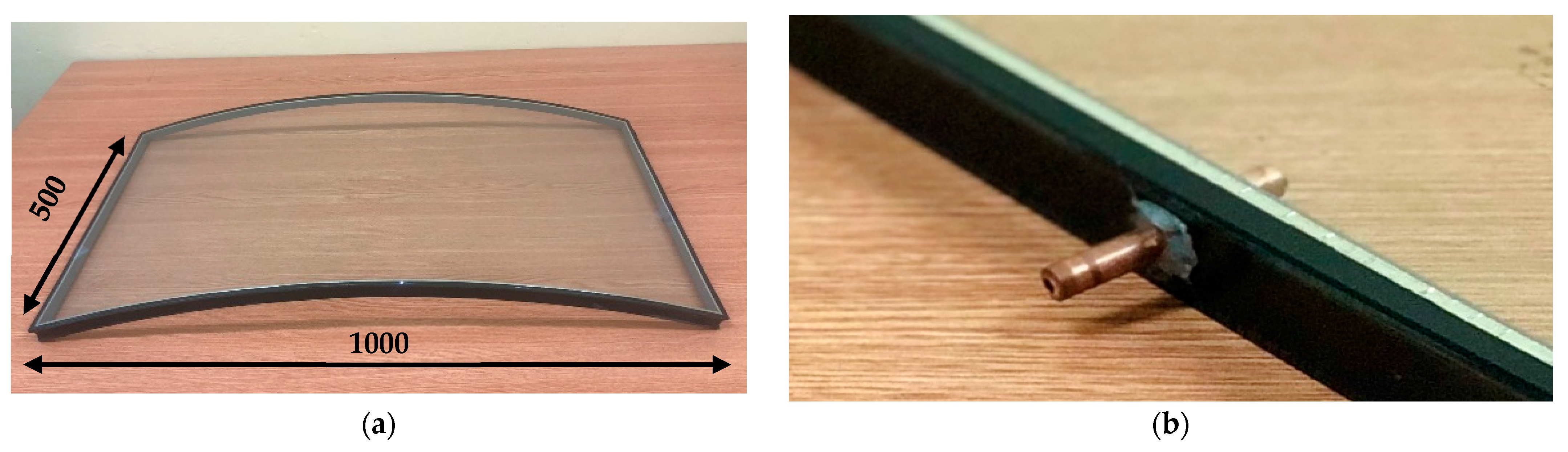
2.1. Experiments

In the experimental part of the work, a curved IGU specimen was produced, with dimensions of 500 × 1000 mm2 (width × arch length) and a 1500 mm radius of curvature (Figure 1a). The specimen was composed of two 4 mm panes made of toughened glass, a 16 mm wide flexible silicone foam spacer, and a 6 mm wide hot-melt secondary sealant. Before testing, two holes were drilled in the spacer, and copper tubes, 6 mm in diameter, were glued into the holes (Figure 1b). Subsequently, silicone conduits were mounted at the ends of the tubes and connected to some laboratory equipment (a set of syringes with a maximum capacity of 300 mL and a pressure sensor). Insulating glass units are typically mounted in frames through flexible gaskets, which partly support the glass. The specimen was tested in a vertical position in a simply supported set-up that allowed for its unrestrained deformation during testing. This set-up was chosen to detect any deformation of the IGU specimen under loading.
A single series of tests involved injecting or withdrawing a defined air volume into/from the IGU cavity [7]. After the procedure, pressure measurements were performed for 5 min, until the stabilisation of the pressure. The test campaign consisted of eight tests, including air injection and withdrawal into/from the cavity ranging from ±75 mL to ±300 mL with a 75 mL margin. More details on the experimental campaign can be found in [8].

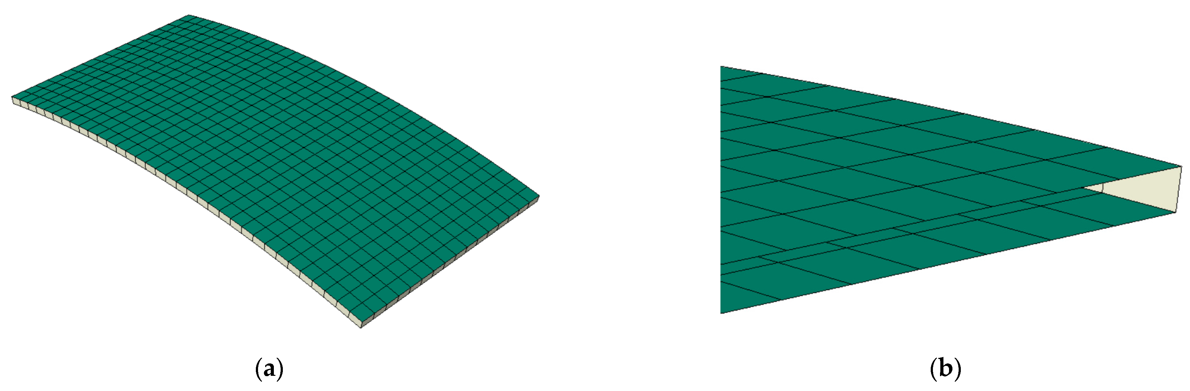
2.2. Development of the Numerical Model of the Curved IGU

Numerical models were developed in the ABAQUS CAE finite element analysis programme to investigate the behaviour of IGUs in the experiments described in Section 2 [9]. A script in Python language was developed to improve the speed of the model generation process. The numerical models differ only by the volume of injected/withdrawn gas, whereas other parameters, such as the geometry of the sample, material properties, and boundary conditions, remain the same. Since creating eight numerical models in the ABAQUS GUI (Graphical User Interface) would consume significant time, a Python script was developed to accelerate the process, in which each syntax reflected the ABAQUS program commands. The variable parameter, in this case the volume of gas, was assigned as input data. The script was developed in the loop, taking another set of input data each time while passing through the code. Applying the Python script to the modelling process significantly reduces the time of the process. The numerical analysis time was limited to the execution of the Python code and computing of the data. As a result, a simple 3D model was created, with dimensions of 500 × 1000 mm2 and a 1500 mm radius of curvature. The model consists of shell parts with square 4-node finite elements with full integration (S4 from the ABAQUS library [9]) and a fluid cavity. Two parallel shells represent the glass panes, while four perpendicular shells correspond to the foamed spacer bar and the secondary sealing (see Figure 2). The fluid cavity was implemented for gas simulation in the air cavity of the IGU. It was vital to create fluid exchange as an injected/withdrawn volume of gas similar to the test conditions.
The following gas constants described the fluid cavity: the universal gas constant Ru = 8.314 J/(K·mol) [10] and the molecular weight of dry air: Mair = 28.97 × 10⁻³ kg/mol [11]. In addition, it was crucial to assign the appropriate physical parameters, such as the thermal expansion coefficient and density, to the air, which were necessary to perform the temperature load analysis. The thermal expansion coefficient was equal to 0.00343 1/K, and the density was 1.204 kg/m3. The model was simply supported and free to deform. The material properties for the glass parts were taken from EN 572-1 (E = 70 GPa, μ = 0.23) [12], while for the spacer, E = 4.6 GPa and μ = 0.49 were used according to [13]. Kozłowski et al. [8] reported a more detailed description of the material properties and the parameters of the fluid cavity. In the same article, a mesh convergence study for maximal stress was performed for similar model parameters, and the model converged to an acceptable degree (change in stress not greater than 2% compared to the previous iteration step). Consequently, in the following research, the same mesh size was assumed, which was equal to 34 points of division along the longer edge of a glass component.

2.3. Case Study

Within the case study, the influence of the curvature of the component panes of an IGU on the internal pressure and static values (stress in glass and panes’ deflection) under the same loading conditions was investigated. For this purpose, the validated numerical model and methodology described in the previous section were used.
Two geometries of an IGU were considered. The first case is a flat reference IGU with the dimensions of 500 × 1000 mm2 (width × length) composed of two 4 mm flat panes and a 16 mm wide flexible silicone foam spacer. The build-up and spatial geometry of the second model are the same as for the reference IGU; however, the component panes are bent to a radius of curvature of 1500 mm.
The analysis was limited to two load cases, according to [6]. The standard provides two climatic design situations for IGUs that generate extreme internal pressure values in the cavity in summer and winter (Table 1). It can be seen that the climatic load in winter is almost a reverse version of summer. The load cases involve temperature differences in the gas in the cavity and changes in atmospheric pressure.

3. Results

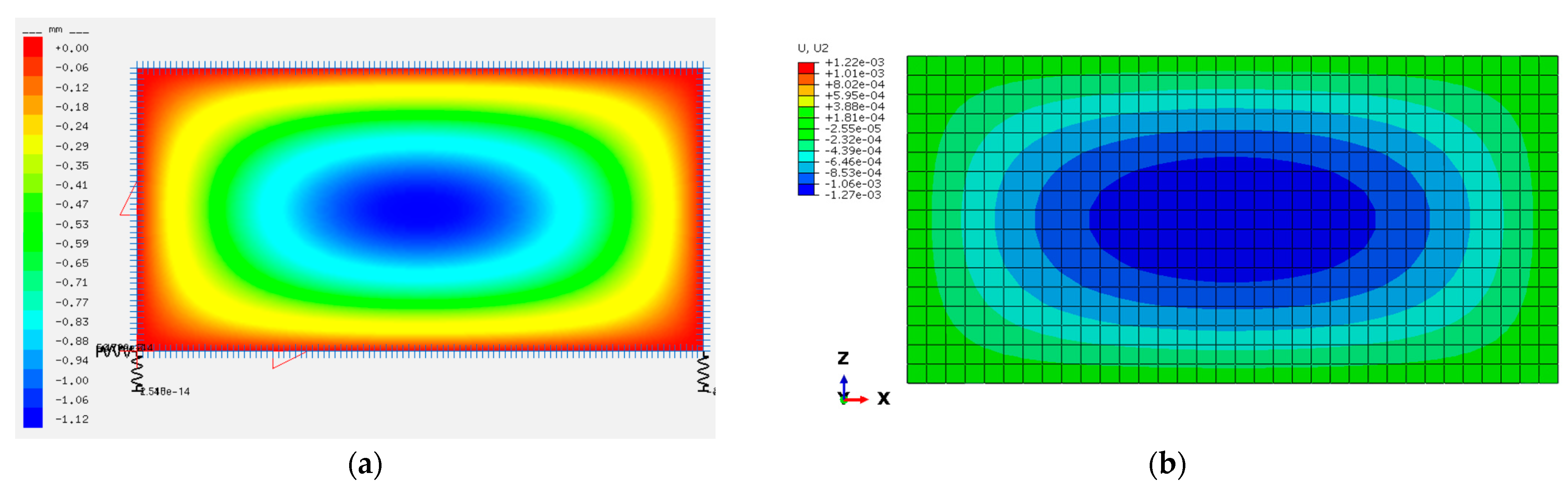
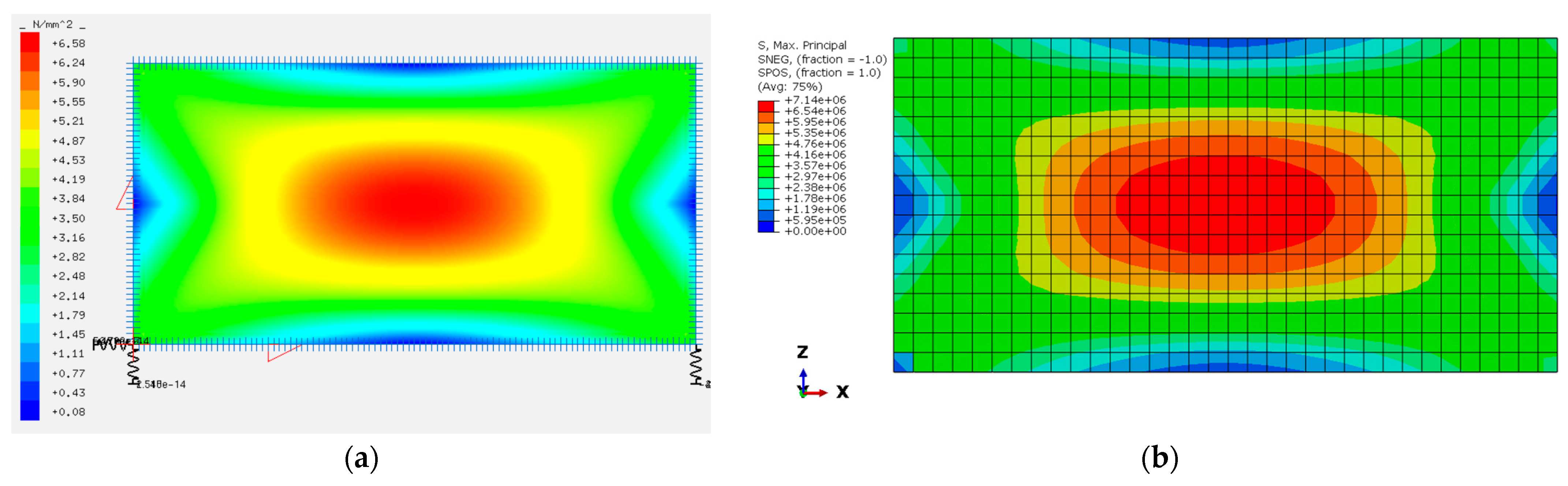
3.1. Validation of the Curved IGU Model by Physical Experiments

Table 2 presents the quantitative results of the experiments and numerical simulations. In general, the numerical model underestimates the measured values by approximately 8%, which proves its correctness and the sound reproduction of the experimental results. Considering all the measured and simulated values pairs, the relationship shows excellent agreement (R2-value 0.99). The most significant difference was 10.8% for the withdrawal of 75 mL from the cavity. The difference between the measured and simulated values of the internal pressure is probably due to how the interface between the spacer and the panes is modelled. It exhibits a hinged connection, which does not transfer any bending moments between the components. In physical samples, the interface provides a certain degree of restraint that limits the deformation of the panes and results in increased pressure inside the space between the panes.

3.2. Validation of the Reference (Flat) IGU Model with Alternative Software

The modelling methodology and material parameters for the flat IGU were the same as those for the validated bent glass IGU model. Since laboratory tests did not include a flat IGU, additional model validation was carried out using the engineering programme SJ-Mepla, widely used for the structural design of IGUs in the glass industry [14]. Only the temperature difference load case included in Table 1 was selected for validation purposes.
Figure 3 and Figure 4 present the validation results for the ‘summer’ case. The results agree regarding the deformation and maximum principal (tensile) stress. Differences are less than 11%. In terms of internal pressure, the numerical model overestimates the reference values (obtained from SJ-Mepla) by approximately 4.5% (701 Pa vs. 733 Pa). The same overestimation was achieved in the ‘winter’ load case. The difference between the models and consequent results is related to the fact that, contrary to the modelling approach developed within this study, the SJ-Mepla software never regards the bending rigidity, i.e., no bending stiffness of the spacer nor the sealing material is used [14]. The results obtained prove the correctness of the flat IGU model.

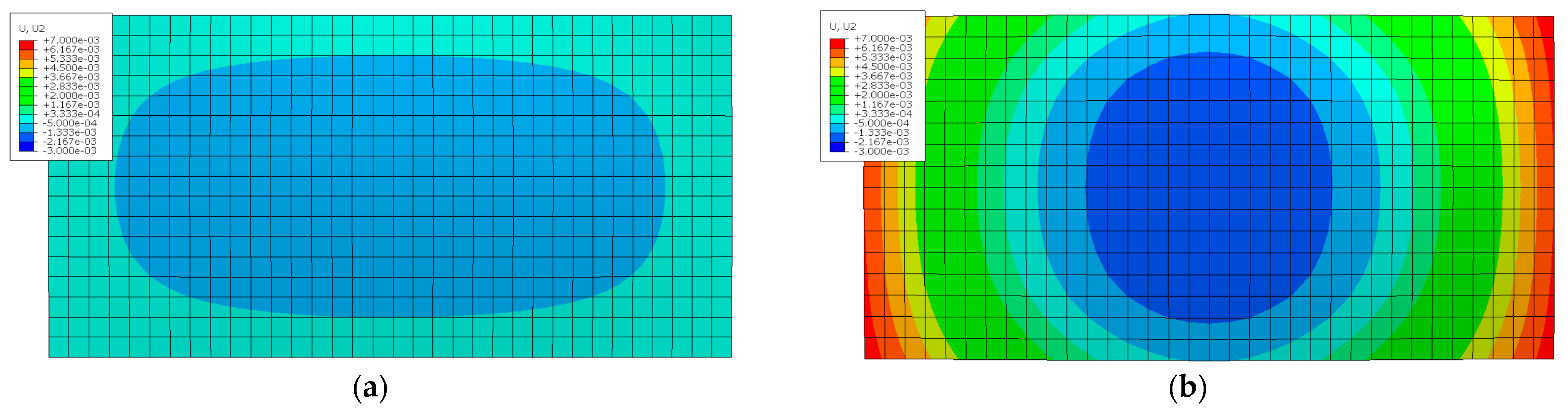
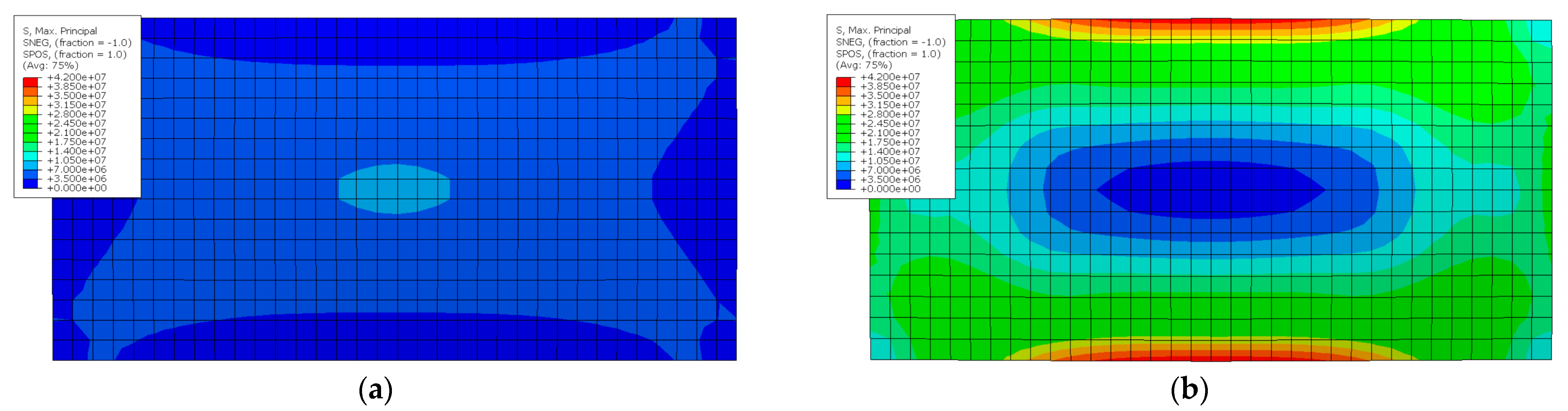
3.3. Results of the Case Study

Figure 5 and Figure 6 present qualitative results of flat and curved IGUs for a selected climatic load case. It should be noted that the graphical results are for the same ‘summer’ load case (Table 1), while quantitative results for both climatic load cases are shown in Table 3.
Figure 5 presents results for flat and cylindrically curved IGU in terms of out-of-plane displacements for the ‘summer’ load case. From the comparison, it can be observed that the curvature of the component pane has a significant influence on the deformation pattern. In the case of flat IGU, the panes bulge with the maximum displacement value in the centre of the pane. This behaviour is typical for rectangular, simply supported flat slabs at all edges and subjected to uniform pressure. Surprisingly, the curved IGU shows a completely different deformation behaviour. The increased pressure in the cavity due to gas expansion caused by the temperature increase and negative air pressure surrounding the IGU causes the model to ‘flatten’, being closer to a flat shape. This way, the short edges are lifted concerning the model’s centre and achieve the maximum values at these locations.
Figure 6 shows maps of maximum principal (tensile) stress in glass, which is a critical factor in structural glazing design. For the flat IGU, the stress map follows the deformation pattern so that the location of the maximum stress is identical to the case of maximum deformation. As for deformation, the stress map is typical for a simply supported flat slab at all edges and subjected to uniform pressure. As seen in the figure, the location of the maximum stress in the curved IGU changes its location. The maximum stress for curved IGU is located at the curved edges of the component panes. This phenomenon is directly related to flattening panes, generating tension in the centre of the curved edges.
Table 3 presents the quantitative results of the case study. In terms of internal pressure, the radius of curvature of 1500 mm causes an average 477% increase in the value for the ‘summer’ load case, while for the ‘winter’ case, the increase is still significant; however, to a lower extent (218%). Regarding maximum deflection and stress, the curvature generates static values higher by, on average, 517% in curved IGU compared to the flat model.

4. Conclusions and Further Work

This paper presents the results of experiments and numerical simulations of a case study involving a flat and cylindrically curved IGU subjected to characteristic climatic actions given in the standards.
It was found that the curvature of the component panes significantly influences the internal pressure, deformation pattern, and stress in the glass of the IGU subjected to climatic loads. The flat IGU uniformly bulges (the pillowing effect), while the curved IGU tends to ‘flatten’ with lifting short edges. This phenomenon is also reflected in the stress distribution. Its maximum value changes location from the centre of the pane (flat IGU) to the centre of the long edge in the curved IGU. The value of principal tensile stress increases significantly by more than 500% in the curved IGU. This finding is critical for the structural design of the panes and the secondary sealant and therefore justifies undertaking the research topic.
It should be emphasised that the above conclusions are valid only for the assumptions used in the case study. The influence of the curvature of the component panes of an IGU on the resulting internal pressure is highly complex and requires further research. It includes investigations of the impact of spacer stiffness and the interface between the glass panes and the spacer.

Author Contributions

Conceptualisation, M.K. and K.Z.; methodology, M.K. and K.Z.; software, M.K. and K.Z.; validation, M.K. and K.Z.; formal analysis, M.K. and K.Z.; investigation, M.K. and K.Z.; resources, M.K. and K.Z.; data curation, M.K. and K.Z.; writing—original draft preparation, M.K.; writing—review and editing, M.K. and K.Z.; visualisation, M.K. and K.Z.; supervision, M.K.; project administration, M.K.; funding acquisition, M.K. All authors have read and agreed to the published version of the manuscript.

Funding

This research was funded by the research project “Analysis of internal pressure in 3D bent insulated glass units” (grant number 2021/05/X/ST8/00168) financed by The National Science Centre (NCN) within the MINIATURA 5 programme.

Institutional Review Board Statement

Not applicable.

Informed Consent Statement

Not applicable.

Data Availability Statement

Data will be provided upon request.

Acknowledgments

The authors thank their colleagues and students from the Faculty of Civil Engineering at the Silesian University of Technology, Gliwice, Poland, for their support during the experiments. Moreover, the insight and expertise provided by Zbigniew Respondek, PhD from the Faculty of Civil Engineering at the Czestochowa University of Technology, Częstochowa, Poland, is acknowledged. The publication cost of this paper was covered with funds from the Polish National Agency for Academic Exchange (NAWA): “MATBUD’2023—Developing international scientific cooperation in the field of building materials engineering” BPI/WTP/2021/1/00002, MATBUD’2023.

Conflicts of Interest

The authors declare no conflict of interest.

References

  1. Kosić, T.; Svetelć, I.; Cekić, Z. Complexity of Curved Glass Structures. IOP Conf. Ser. Mater. Sci. Eng. 2017, 262, 012158. [Google Scholar] [CrossRef]
  2. Malewski, A.; Kozłowski, M.; Sumelka, W.; Połedniok, M. Large Scale Architectural Glass Slumping Process-Challenges and Limitations. Arch. Civ. Eng. 2020, 66, 485–505. [Google Scholar] [CrossRef]
  3. Kocer, C.; Aronen, A.; Collins, R.; Asano, O.; Ogiso, Y. Measurement of heat flow through vacuum insulating glass part 2: Measurement area separated from glass sheets with buffer plates. Glass Struct. Eng. 2022. [Google Scholar] [CrossRef]
  4. Nizich, A.; Baer, S.; Prandelli, S.; Burkhart, I.K.; Moore, W.P. Enhancing the Light-Curved Insulated Glass Unit Design Study Keywords; GPD Glass Performance Days: Tampere, Finland, 2019. [Google Scholar]
  5. Bao, M.; Gregson, S. Sensitivity study on climate induced internal pressure within cylindrical curved IGUs. Glass Struct. Eng. 2019, 4, 29–44. [Google Scholar] [CrossRef]
  6. DIN 18008-1; Glass in Building—Design and Construction Rules—Part 1: Terms and General Bases. Deutsches Institut fur Normung E.V. (DIN): Berlin, Germany, 2010.
  7. Kozłowski, M.; Respondek, Z.; Wiśniowski, M.; Cornik, D.; Zemła, K. Experimental and Numerical Simulations of Climatic Loads in Insulating Glass Units by Controlled Change of Pressure in the Gap. Appl. Sci. 2023, 13, 1269. [Google Scholar] [CrossRef]
  8. Kozłowski, M.; Respondek, Z.; Cornik, D.; Wiśniowski, M.; Zemła, K. Influence of Curvature and Geometrical Parameters on Internal Pressure in Cylindrical Insulating Glass Units. Thin-Walled Struct. 2023; in review. [Google Scholar]
  9. SIMULIA. Abaqus/CAE User’s Guide; SIMULIA: Johnston, RI, USA, 2014. [Google Scholar]
  10. Jensen, W. The Universal Gas Constant R. J. Chem. Educ. 2003, 60, 7. [Google Scholar] [CrossRef]
  11. Rajput, R.K. Engineering Thermodynamics: A Computer Approach; Transatlantic Publishers: London, UK, 2003. [Google Scholar]
  12. EN 572-1:2012; Glass in Building Basic Soda Lime Silicate Glass Products—Definitions and General Physical and Mechanical Properties. CEN: Brussels, Belgium, 2012.
  13. Minasyan, M. Randverbundbeanspruchung Gebogener Zweischeiben-Isoliergläser mit Silikonschaum-Abstandhalter; Hamburg University: Hamburg, Germany, 2014. [Google Scholar]
  14. SJ Software GmbH. SJ MEPLA Software and User’s Manual; SJ Software GmbH: Aachen, Germany, 2021. [Google Scholar]
Figure 1. Experimental study: (a) Curved IGU sample; (b) Copper tube glued into a hole drilled in the spacer.
Materproc 13 00012 g001
Figure 2. Numerical model of the curved IGU: (a) Finite element mesh; (b) Detail of the glass–spacer interface. Note: glass panes are shown in green, while spacers are grey.
Materproc 13 00012 g002
Figure 3. Validation of the flat IGU model (‘summer’ load case): (a) deflections obtained from the SJ-Mepla software (values in mm); (b) deflections obtained from the ABAQUS software (values in m).
Materproc 13 00012 g003
Figure 4. Validation of the flat IGU model (‘summer’ load case): (a) maximum principal (tensile) stress obtained from the SJ-Mepla software (values in MPa); (b) maximum principal (tensile) stress obtained from the ABAQUS software (values in Pa).
Materproc 13 00012 g004
Figure 5. Out-of-plane displacements (‘summer’ load case) for: (a) flat IGU; (b) curved IGU. Note: Bottom view; values in m; the same scale was used for the legend on both figures (max: 7.0 mm, min: −3.0 mm).
Materproc 13 00012 g005
Figure 6. Maximum principal tensile stress (‘summer’ load case) for: (a) flat IGU; (b) curved IGU. Note: Bottom view; values in MPa; the same scale was used for the legend on both figures (max: 42 MPa).
Materproc 13 00012 g006
Table 1. Load actions by [6].
Load CaseTemperature Difference [K]Change in Atmospheric Pressure [kN/m2]
‘Summer’+20−2.0
‘Winter’−25+4.0
Table 2. Comparison of measured and simulated values of internal pressure in the IGU cavity.
Loading (Air Injection/Withdrawal to/from IGU Cavity)Internal Pressure [Pa]Difference (Simulated vs. Measured)
Measured ExperimentallySimulated Numerically
+75 mL528.6482.5−8.7%
+150 mL1066.8960.1−10.0%
+225 mL1582.41435.7−9.3%
+300 mL2092.71906.7−8.9%
−75 mL−543.1−484.4−10.8%
−150 mL−1064.3−970.4−8.8%
−225 mL−1556.3−1464.0−5.9%
−300 mL−2097.2−1594.5−6.8%
Table 3. Results of the case study.
Load Case Flat IGUCurved IGUDifference
‘Summer’Internal pressure [Pa]11905680+477%
Maximum principal tensile stress [MPa]7.6341.21+540%
Deflection in the Y direction [mm]1.356.79+503%
‘Winter’Internal pressure [Pa]−2870−6250+218%
Maximum principal tensile stress [MPa]8.8951.46+579%
Deflection in the Y direction [mm]1.757.86+449%
Disclaimer/Publisher’s Note: The statements, opinions and data contained in all publications are solely those of the individual author(s) and contributor(s) and not of MDPI and/or the editor(s). MDPI and/or the editor(s) disclaim responsibility for any injury to people or property resulting from any ideas, methods, instructions or products referred to in the content.

