Proceeding Paper

Influence of Spent Fluid Catalytic Cracking Catalyst on the Properties of the New Binder Based on Fly Ash and Portland Cement †

by
Jelena Rakić
and
Zvezdana Baščarević
*
Institute for Multidisciplinary Research, Belgrade University, Kneza Višeslava 1, 11000 Belgrade, Serbia
*
Author to whom correspondence should be addressed.
Presented at the 10th MATBUD’2023 Scientific-Technical Conference “Building Materials Engineering and Innovative Sustainable Materials”, Cracow, Poland, 19–21 April 2023.
Mater. Proc. 2023, 13(1), 8; https://doi.org/10.3390/materproc2023013008
Published: 14 February 2023
(This article belongs to the Proceedings of 10th MATBUD’2023 Scientific-Technical Conference)

Abstract

:
One of the measures to reduce the carbon footprint of the Portland cement (PC) manufacturing process is through a wider use of supplementary cementitious and waste materials. The main objective of this work was to produce a new binder using two different waste materials: fly ash (FA) from thermal power plants and spent fluid catalytic cracking catalyst (sFCCC) from petrol refineries. In order to improve their reactivity, both FA and sFCCC were mechanically activated prior to the preparation of the binder. The new binder consisted mostly of the waste materials (70 mass %), with PC as a minor component (30 mass %). It was found that using sFCCC as the binder component accelerated cement hydration and the pozzolanic reaction. The new binder had a shorter setting time and a higher early strength than the binder prepared without sFCCC.

1. Introduction

Fly ash (FA) is waste material generated by coal combustion in power plants. It is a fine aluminosilicate powder and owing to these properties, FA has been used for decades as cement and/or a concrete component. However, when FA is used as the major component in high volume FA–Portland cement (PC) blends, it causes prolonged setting time and delayed strength development of a binder [1]. Although the reactivity of FA and early age properties of high volume FA binders can be improved by using chemical activators [1,2], it often results in decreased strength of a binder at later ages.
Spent fluid catalytic cracking catalyst (sFCCC) is a waste material from petrol refineries that consists mostly of zeolite and an amorphous aluminosilicate matrix. Due to relatively small quantities of sFCCC produced (200,000–400,000 tons per year globally [3]), landfilling is often considered as the most economical option for its disposal. This waste material can be used as a cement additive, although its amount in binder is limited by the fact that it can cause short setting time and increased water demand [2,4,5].
Previous studies demonstrated that using sFCCC as a component of blended cements (70–80% of cement in the binder) had a positive impact on the binder properties [6,7,8]. However, little work has been done so far on investigating the possibilities of using sFCCC as part of a binder in which higher amounts of cement were replaced by waste materials, such as FA. Calorimetric and thermal analyses of very high volume FA binders (20% of cement in the binder) showed that using sFCCC as a FA replacement in the binder accelerated both cement hydration and the pozzolanic reaction [4].
The aim of this work was to further investigate the effects of replacing part of FA in the high volume FA binder (70 mass %) with sFCCC. It was expected that the use of sFCCC as the binder component would shorten setting times and increase early compressive strength of the binder. In order to evaluate the effects of using sFCCC as the binder component, setting time, compressive strength, mineral composition and microstructure of the new binders were analyzed.

2. Materials and Methods

FA used in this work was from “Nikola Tesla B” power plant (Serbia). The sFCCC sample was obtained from a local petrol refinery. Portland cement CEM I 52.5 N (CEM, Našice cement, Nexe d.d., Našice, Croatia) was used as a minor component of the new binder.
As-received FA and sFCCC were mechanically activated in a planetary ball mill (Fritsch Pulverisette 05 102, Fritsch GmbH, Idar-Oberstein, Germany). The mechanical activation of FA was conducted in stainless steel bowls (500 cm3 in volume) using 13 mm diameter steel balls, with a 1:3 FA to balls ratio, at 380 rpm and lasting for 15 min. The sFCCC sample was ground for 20 min at 200 rpm in corundum grinding bowls (500 cm3), and the sFCCC to corundum grinding balls (5 mm in diameter) mass ratio was 1:3.
Particle size distribution (PSD) of the materials was analyzed using Mastersizer 2000 (Malvern Panalytical, Malvern, UK).
The chemical composition of the binder components was determined by energy dispersive X-ray fluorescence spectrometer ED2000 (Oxford Instruments, Abingdon, UK).
X-ray diffraction analysis (XRD, Rigaku Smart Lab, Rigaku, Tokyo, Japan), with Cu anticathode operating at 40 kV and 30 mA, was used to determine mineral composition of the starting materials and the new binder pastes. The XRD analyses were conducted in the 5–55 °2θ range, with 0.01° step and 2°/min recording speed.
As-received and grinded FA and sFCCC, as well as resulting binder samples, were examined using a scanning electron microscope (SEM, VEGA TS 5130 MM, Tescan, Brno, Czech Republic) equipped with a backscattered detector (BSE, Tescan). Before the analyses, the samples were Au-coated.
The new binders were prepared by dry mixing the waste materials and CEM in 70:30 mass ratios for 5 min. Paste samples were made by mixing the binder with water (Table 1), provided that the standard consistency was achieved [9]. The setting time of the pastes was determined following the recommendations given in EN 196-3 [9].
Binder mortars were prepared by mixing the binder with water and standard sand [10]. Water to binder (w/b) ratios of the new binder mortars were aimed at providing workability similar to the workability of the CEM mortar prepared with w/b = 0.50 [10,11]. Therefore, the w/b ratio of the mortar based only on FA (binder FA70) was 0.57 and the w/b ratio of the mortar prepared with both of the waste materials (FCCC21) was 0.58.
Paste and mortar samples were cured in a humid chamber (relative humidity ~90%, temperature 20 ± 2 °C) until testing.
The compressive strength of the mortars was determined using Matest testing machine E161 (Matest, Treviolo, Italy) [9].

3. Results and Discussion

3.1. Characterization of the Binder Components

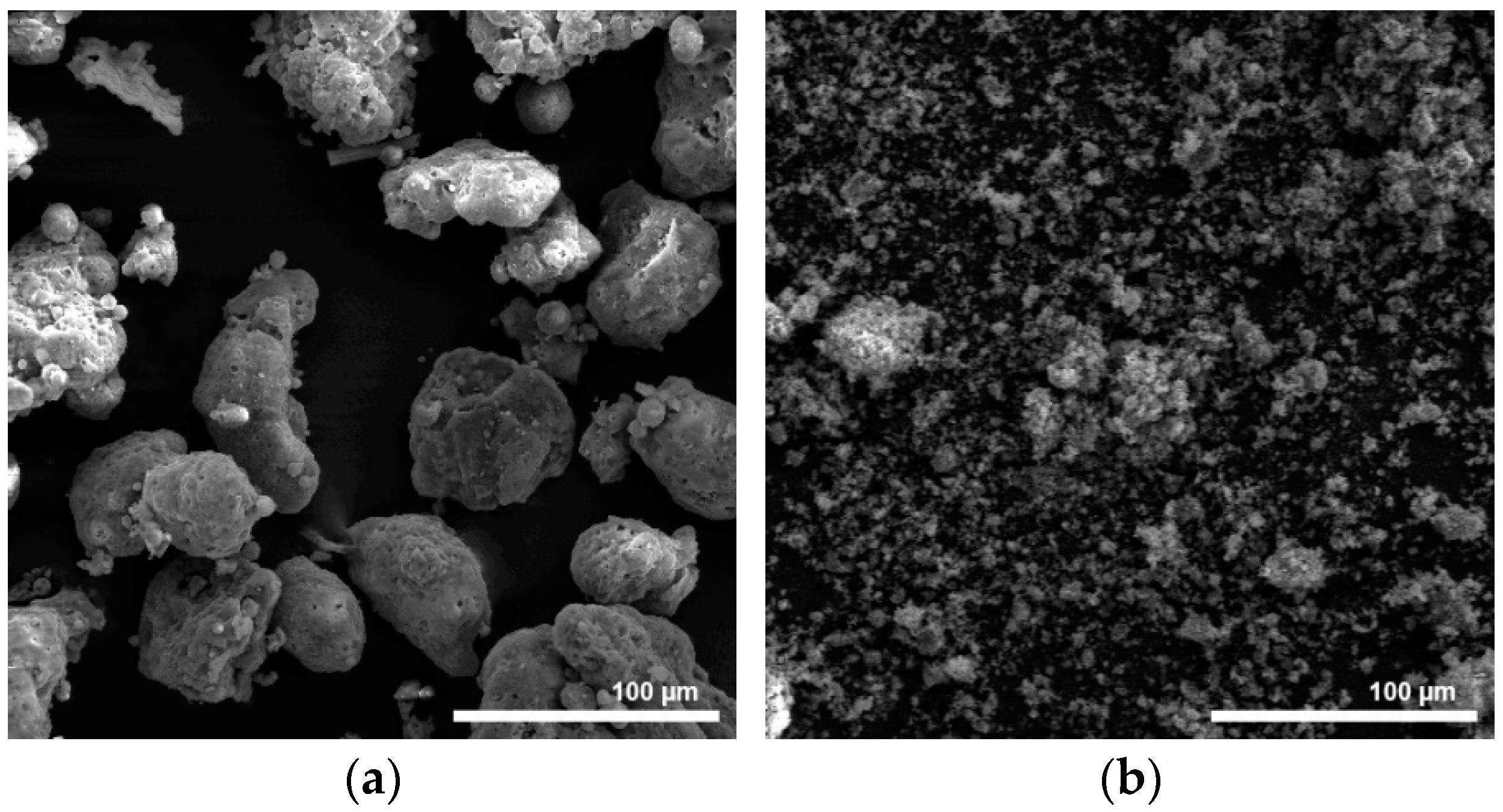
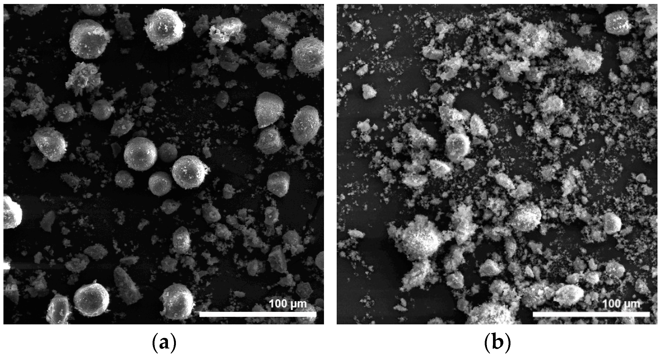
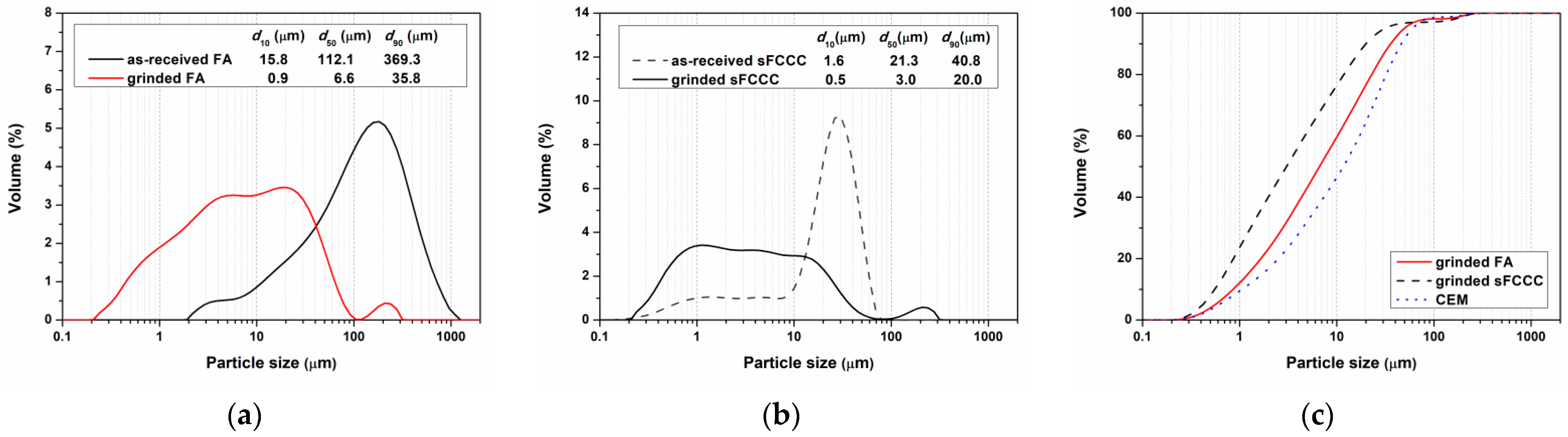
3.1.1. Effects of the Mechanical Activation on Morphology and Particle Size Distribution of FA and sFCCC

The as-received FA sample consisted mainly of large particles (~100 µm), irregular in shape (Figure 1a). The grinding of the FA sample in the planetary ball mill for only 15 min provided a material with fine particles, mostly smaller than 10 µm (Figure 1b).
The sFCCC sample obtained from the local petrol refinery contained spherical particles, ~20 µm in diameter, and smaller irregular particles (Figure 2a). After the mechanical activation of the as-received sFCCC sample, most of the spherical particles were broken. However, SEM analysis of the ground sFCCC sample showed the presence of agglomerates (Figure 2b).
Particle size distribution analyses of the as-received and ground FA and sFCCC demonstrated that mechanical activation, for only 15 min, resulted in a substantial decrease in particle sizes of both of the materials (Figure 3a,b). It has already been demonstrated that mechanical activation increases the reactivity of these waste materials [12,13,14,15]. The fact that the PSD of the mechanically activated FA and sFCCC was almost similar to the PSD of CEM (Figure 3c) could also have a positive impact on the mixing of the powders when preparing the binder [16].

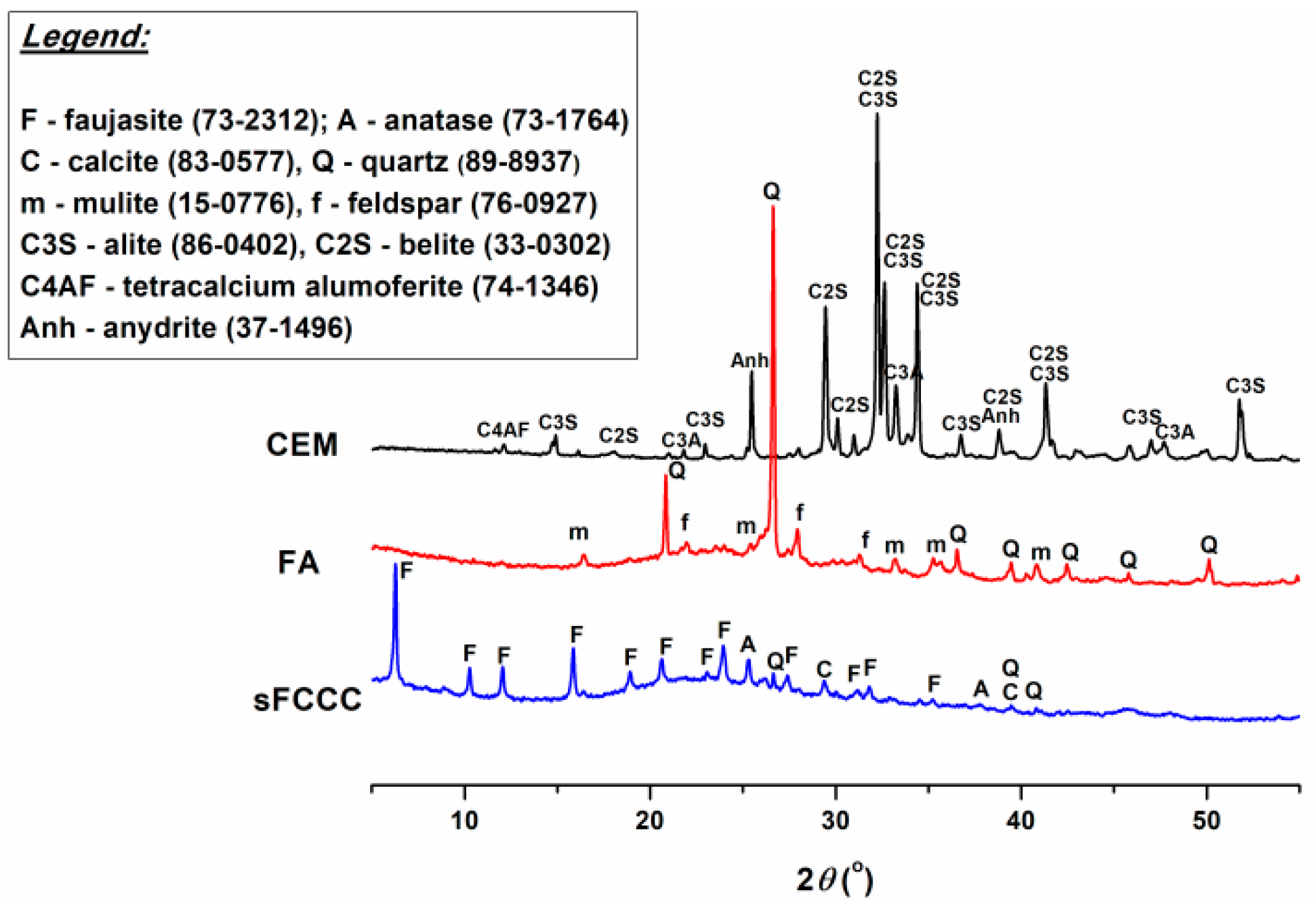
3.1.2. Chemical and Mineral Composition of the Binder Components

Table 2 shows the chemical composition of the materials used for the preparation of the new binder (the CEM sample and the ground FA and sFCCC samples, hereinafter referred to as FA and sFCCC). The FA produced by Serbian power plants originates from burning lignite and usually belongs to class F [17,18]. The FA sample used in this work consisted mostly of SiO2 and Al2O3, with a relatively high content of CaO (Table 2). The sFCCC sample was rich in Al2O3 and contained approximately equal amounts of SiO2 and Al2O3 (~42 mass %), while the chemical composition of the CEM sample was typical for the material.
XRD analyses also showed that the mineral composition of the FA, sFCCC and CEM samples was typical for these materials (Figure 4). Clinker minerals and anhydrite were detected in the CEM sample, while quartz peaks were the most prominent in the XRD graph of the FA sample. Crystalline zeolite faujasite was detected in the sFCCC sample. The presence of the amorphous phases in the both of the waste materials was indicated by the shape of the baselines in the 15–35 °2θ range (Figure 4).

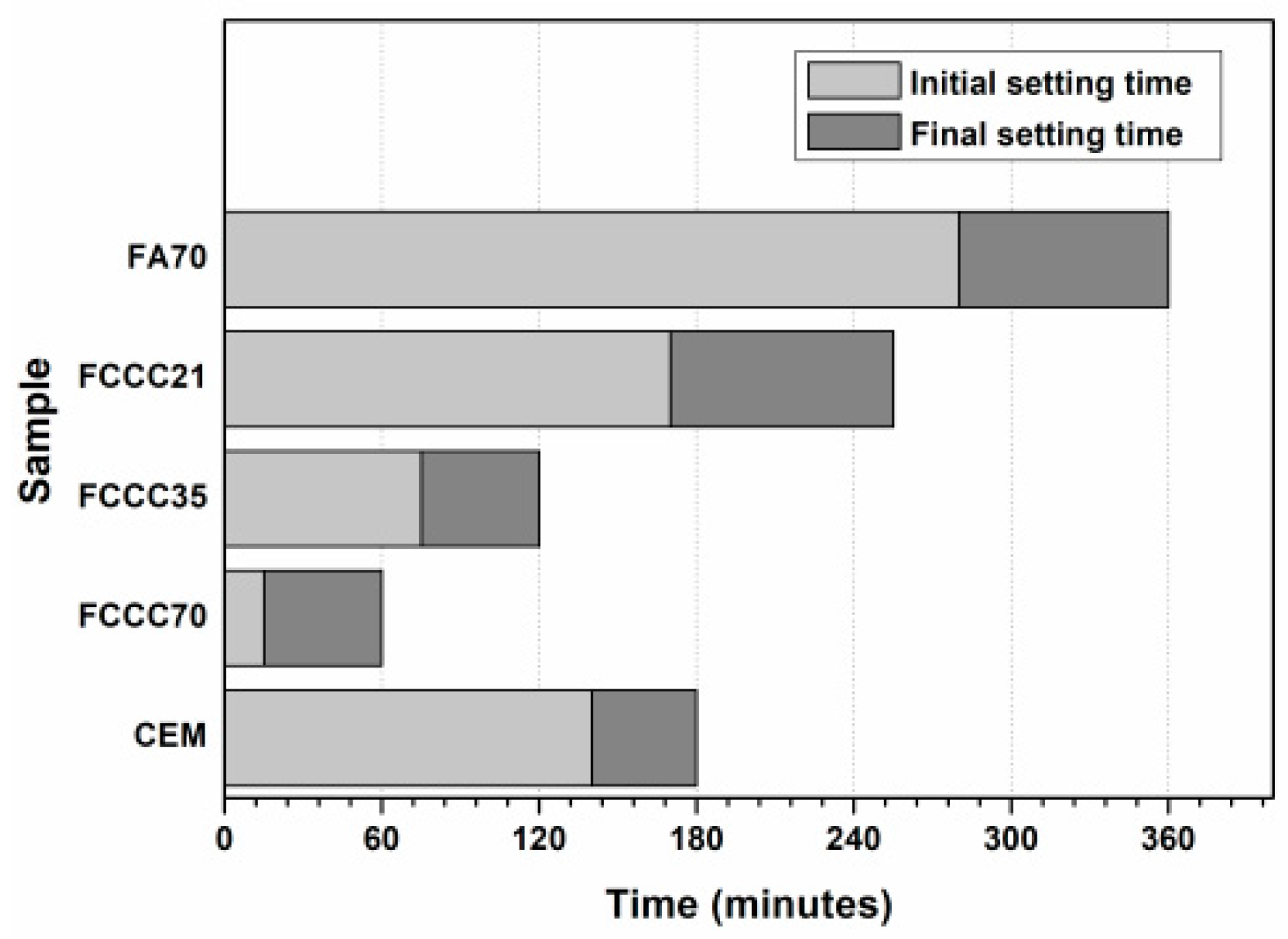
3.2. Influence of sFCCC on Setting Times of the New Binder

Figure 5 shows the setting times of the prepared binder pastes. The paste made only with the sFCCC and Portland cement (FCCC70) showed a flash setting (initial setting was observed already after 15 min), while the setting times of the paste prepared with FA and CEM (FA70) were significantly longer than the setting times of the paste prepared with pure cement (CEM). Decreasing percentages of the FA were substituted with the sFCCC in the binder mixes (starting from 50 mass %, Figure 5, binder FCCC35) in order to obtain the new binder with setting times shorter than the setting times of the FA70 paste, but comparable to setting time of the cement paste. Finally, the binder prepared with 21 mass % of the sFCCC (FCCC21) showed the envisaged properties regarding setting times, and was used for further studies. The goal of this approach was to use sFCCC as an activating component of the binder. The setting times of the new binder should be shorter than the setting times of the binder based only on FA. The obtained results confirmed that sFCCC is a very active pozzolanic material [4]. The accelerating effect of the sFCCC in the blended cement pastes has also been attributed to the adsorption of water on the sFCCC particles and to decreased sulfate content in the blended cement [5].

3.3. Compressive Strength of the New Binder

Analyses of the compressive strength of the new binder mortars showed that using sFCCC as the binder component had a positive impact on early (2 days) compressive strength (Table 3). Afterwards, compressive strength of the FA70 binder was higher than the strength of the FCCC21 binder. Relatively high compressive strengths of the FA70 sample were probably achieved due to the fact that mechanically activated FA was used in the preparation of the new binder. Very fine particles of the ground FA acted as nucleation sites and contributed to cement hydration at the early stages [6].

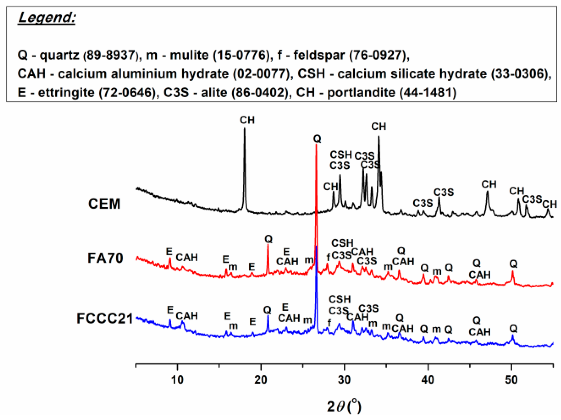
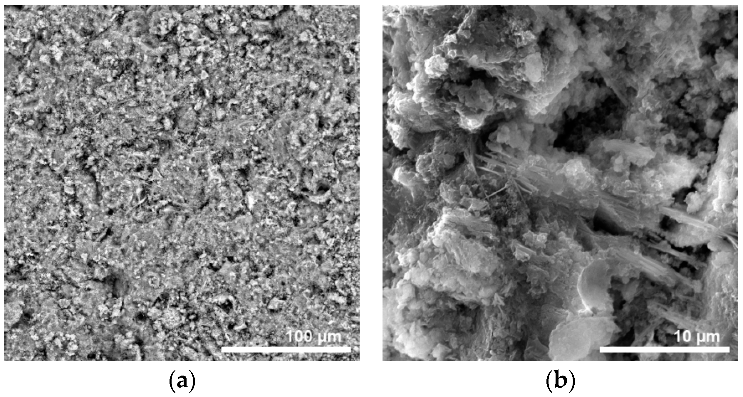
3.4. Mineral Composition and Microstructure of the New Binder

Mineral compositions of the binder pastes based on FA and the combination of FA and sFCCC after 28 days of curing were similar (Figure 6). The main hydration products of the new binders were calcium aluminate hydrate (CAH) and ettringite (E). The shape of the peak at 29.3 °2θ indicated that calcium silicate hydrate (CSH) was probably formed in the new binder pastes too. As seen from Figure 6, portlandite (calcium hydroxide, CH) could not be detected in the XRD graphs of the binders FA70 and FCCC21, cured for 28 days, which could be explained by the low content of cement in the binders and portlandite consumption by the pozzolanic reactions of FA and sFCCC [4]. The XRD analysis of the CEM paste showed a mineral composition typical for the material.
SEM analyses of the FA70 and FCCC21 binder pastes cured for 28 days showed that the microstructure of the new binders was heterogeneous and relatively porous, as seen from the BSE micrographs (Figure 7a and Figure 8a). It seems that the FCCC21 paste was slightly more porous than the FA70 paste, which corresponds with the observed differences in compressive strength (Table 3), and could partly be explained by a higher water/binder ratio of the FCCC21 paste (Table 1). SEM micrographs taken at the higher magnifications confirmed the presence of the hydration products identified by the XRD analyses, probably CSH (Figure 7b) and ettringite (Figure 8b).
The structural characterization of the new binder pastes did not provide an explanation for the observed differences in the strength development of the binder mortars after the first 2 days of curing (Table 3). It is possible that portlandite was consumed in the FCCC21 more quickly than in the FA70 binder due to the high reactivity of sFCCC [4]. The lower strength of the FCCC21 binder after 28 days of curing, compared to the FA70, could also be due to the very fast hydration of the binder containing sFCCC at the beginning of the reaction, and the attachment of the reaction products on the surface of the un-reacted particles [19,20].

4. Conclusions

The spent catalyst from the catalytic cracking in the petrol refinery was used as a component of the high volume fly ash binder. Both of the waste materials were mechanically activated prior to the preparation of the new binder and the ground materials had a PSD comparable to the PSD of commercial cement. It was found that the binder that contained 21 mass % of the sFCCC had setting times comparable to the setting times of cement pastes. The use of the sFCCC as the binder component also had a positive effect on the early (2 days) compressive strength of the binder. However, the compressive strength of the binder prepared without sFCCC was higher at later ages. Structural analyses revealed that the main reaction products of the new binders were calcium aluminate hydrate, calcium silicate hydrate and ettringite, while the microstructure of the binders was heterogeneous and relatively porous. Differences in the observed properties of the binders prepared with and without sFCCC were attributed to the high reactivity of the mechanically activated waste materials.

Author Contributions

Conceptualization, Z.B.; methodology, Z.B. and J.R.; validation, J.R. and Z.B.; formal analysis, J.R.; investigation, J.R.; resources, Z.B. and J.R.; data curation, Z.B. and J.R.; writing—original draft preparation, J.R. and Z.B.; writing—review and editing, Z.B.; supervision, Z.B.; project administration, Z.B.; funding acquisition, Z.B. All authors have read and agreed to the published version of the manuscript.

Funding

This research work was funded by the Ministry of Education, Science and Technological Development, Republic of Serbia, contract number 451-03-68/2022-14/200053 and by the funding of the EUREKA project E! 9980 INBYCON.

Data Availability Statement

The data presented in this study are available on request from the corresponding author. The data are not publicly available due to legal restrictions.

Acknowledgments

The authors are thankful to Sabina Kovač for performing XRD analyses. The publication cost of this paper was covered with funds from the Polish National Agency for Academic Exchange (NAWA): “MATBUD’2023-Developing international scientific cooperation in the field of building materials engineering” BPI/WTP/2021/1/00002, MATBUD’2023.

Conflicts of Interest

The authors declare no conflict of interest.

References

  1. Alahrache, S.; Winnefeld, F.; Champenois, J.; Hesselbarth, F.; Lothenbach, B. Chemical activation of hybrid binders based on siliceous fly ash and Portland cement. Cem. Concr. Compos. 2016, 66, 10–23. [Google Scholar] [CrossRef]
  2. Wilinska, I.; Pacewska, B. Influence of selected activating methods on hydration processes of mixtures containing high and very high amount of fly ash. J. Therm. Anal. Calorim. 2018, 133, 823–843. [Google Scholar] [CrossRef]
  3. Alonso-Fariñas, B.; Rodríguez-Galán, M.; Arenas, C.; Arroyo Torralvo, F.; Leiva, C. Sustainable management of spent fluid catalytic cracking catalyst from a circular economy approach. Waste. Manag. 2020, 110, 10–19. [Google Scholar] [CrossRef] [PubMed]
  4. Wilińska, I.; Pacewska, B. Calorimetric and thermal analysis studies on the influence of waste aluminosilicate catalyst on the hydration of fly ash–cement paste. J. Therm. Anal. Calorim. 2014, 116, 689–697. [Google Scholar] [CrossRef]
  5. Payá, J.; Monzó, J.; Borrachero, M.V. Physical, chemical and mechanical properties of fluid catalytic cracking catalyst residue (FC3R) blended cements. Cem. Concr. Res. 2001, 31, 57–61. [Google Scholar] [CrossRef]
  6. Soriano, L.; Payá, J.; Monzó, J.; Borrachero, M.V.; Tashima, M.M. High strength mortars using ordinary Portland cement–fly ash–fluid catalytic cracking catalyst residue ternary system (OPC/FA/FCC). Constr. Build. Mater. 2016, 106, 228–235. [Google Scholar] [CrossRef]
  7. Da, Y.; He, T.; Wang, M.; Shi, C.; Xu, R.; Yang, R. The effect of spent petroleum catalyst powders on the multiple properties in blended cement. Constr. Build. Mater. 2020, 231, 117203. [Google Scholar] [CrossRef]
  8. Payá, J.; Monzó, J.; Borrachero, M.V. Fluid catalytic cracking catalyst residue (FC3R). An excellent mineral by-product for improving early strength development of cement mixtures. Cem. Concr. Res. 1999, 29, 1773–1779. [Google Scholar] [CrossRef]
  9. SRPS EN 196-3:2017; Methods of Testing Cement–Part 3: Determination of Setting Times and Soundness. Institute for Standardization of Serbia: Belgrade, Serbia, 2017.
  10. SRPS EN 196-1:2017; Methods of Testing Cement–Part 1: Determination of Strength. Institute for Standardization of Serbia: Belgrade, Serbia, 2017.
  11. SRPS EN 1015-3:2008; Methods of Test for Mortar for Masonry–Part 3: Determination of Consistence of Fresh Mortar (by Flow Table). Institute for Standardization of Serbia: Belgrade, Serbia, 2008.
  12. Marjanović, N.; Komljenović, M.; Baščarević, Z.; Nikolić, V. Improving reactivity of fly ash and properties of ensuing geopolymers through mechanical activation. Constr. Build. Mater. 2014, 57, 151–162. [Google Scholar] [CrossRef]
  13. Marjanović, N.; Komljenović, M.; Baščarević, Z.; Nikolić, V. Comparison of two alkali-activated systems: Mechanically activated fly ash and fly ash-blast furnace slag blends. 7th Scientific-Technical Conference Material Problems in Civil Engineering (MATBUD’2015). Procedia Eng. 2015, 108, 231–238. [Google Scholar] [CrossRef] [Green Version]
  14. Pacewska, B.; Wilińska, I.; Bukowska, M.; Blonkowski, G.; Nocuñ-Wczelik, W. An attempt to improve the pozzolanic activity of waste aluminosilicate catalyst. J. Therm. Anal. Calorim. 2004, 77, 133–142. [Google Scholar] [CrossRef]
  15. Baščarević, Z.; Rakić, J.; Petrović, R. Possibility to use spent catalyst from fluid catalytic cracking process for geopolymer synthesis. In Proceedings of the (Tagungsband 1) Internationale Baustofftagung, IBAUSIL, Weimar, Germany, 12–14 September 2018. [Google Scholar]
  16. Musha, H.; Chandratilleke, G.R.; Chan, S.L.I.; Bridgwater, J.; Yu, A.B. Effects of Size and Density Differences on Mixing of Binary Mixtures of Particles. Powders Grains 2013 AIP Conf. Proc. 2013, 1542, 739–742. [Google Scholar] [CrossRef]
  17. ASTM C618-22; Standard Specification for Coal Fly Ash and Raw or Calcined Natural Pozzolan for Use in Concrete. ASTM International: West Conshohochen, PA, USA, 2022.
  18. Komljenović, M.; Baščarević, Z.; Bradić, V. Mechanical and microstructural properties of alkali-activated fly ash geopolymers. J. Hazard Mater. 2010, 181, 35–42. [Google Scholar] [CrossRef] [PubMed]
  19. Lam, L.; Wong, Y.L.; Poon, C.S. Degree of hydration and gel/space ratio of high-volume fly ash/cement systems. Cem. Concr. Res. 2000, 30, 747–756. [Google Scholar] [CrossRef]
  20. He, T.; Da, Y.; Xu, R.; Yang, R. Effect of multiple chemical activators on mechanical property of high replacement high calcium fly ash blended system. Constr. Build. Mater. 2019, 198, 537–545. [Google Scholar] [CrossRef]
Figure 1. SEM micrographs: (a) as-received FA; (b) ground FA.
Materproc 13 00008 g001
Figure 2. SEM micrographs: (a) as-received sFCCC; (b) ground sFCCC.
Materproc 13 00008 g002
Figure 3. Particle size distribution: (a) as-received and ground FA; (b) as-received and ground sFCCC; (c) binder components (cumulative curve).
Materproc 13 00008 g003
Figure 4. Mineral composition of the binder components.
Materproc 13 00008 g004
Figure 5. Setting times of the new binder and CEM pastes.
Materproc 13 00008 g005
Figure 6. Mineral composition of the new binder and CEM pastes cured for 28 days.
Materproc 13 00008 g006
Figure 7. SEM analyses of the FA70 paste after 28 days of curing: (a) microstructure; (b) reaction products.
Materproc 13 00008 g007
Figure 8. SEM analyses of the FCCC21 paste after 28 days of curing: (a) microstructure; (b) reaction products.
Materproc 13 00008 g008
Table 1. Binder samples denotation and composition.
BinderComposition (mass %)Water/Binder Ratio
FAsFCCCCEM
CEM001000.29
FCCC70070300.47
FCCC353535300.46
FCCC214921300.45
FA70700300.43
Table 2. Chemical composition of the starting materials.
Composition (mass %)FAsFCCCCEM
LOI (1000 °C)2.695.552.54
SiO261.5141.9720.17
Al2O315.9142.865.36
Fe2O37.791.862.86
CaO8.454.7962.04
MgO0.350.432.17
SO30.190.103.38
Na2O0.350.010.45
K2O1.010.070.75
P2O50.060.47-
TiO21.461.61-
SUM99.7799.7299.72
Table 3. Compressive strength of the new binder and CEM mortars.
Compressive Strength (MPa)CEMFA70FCCC21
2 days31.9 ± 0.96.0 ± 0.27.0 ± 0.2
7 days48.8 ± 0.615.0 ± 0.514.8 ± 0.3
28 days57.8 ± 2.132.9 ± 0.726.9 ± 0.9
Disclaimer/Publisher’s Note: The statements, opinions and data contained in all publications are solely those of the individual author(s) and contributor(s) and not of MDPI and/or the editor(s). MDPI and/or the editor(s) disclaim responsibility for any injury to people or property resulting from any ideas, methods, instructions or products referred to in the content.

