1. Introduction
An air conditioner with the ability to both lower and maintain humidity levels is known as a dehumidifier. The elimination of musty odors and the prevention of mildew development by removing water from the air are common reasons for this practice, along with health and thermal comfort concerns. Moisturizers are machines that draw moisture out of the air. Dehumidifiers work by drawing in air, cooling it using coils, and then releasing the drier air into the room via warmer coils. Dehumidifiers may be broadly classified into two categories: condensate and desiccant. Reusable water may be collected by condensate dehumidifiers via the refrigeration cycle. Absorption dehumidifiers and desiccant dehumidifiers are interchangeable terms for the same technology, which bonds hydrophilic material to moisture content. Thermoelectric dehumidifiers, also known as Peltier or Peltier effect dehumidifiers, work by converting electrical currents into a temperature differential across a Peltier module, which is a process known as the thermoelectric effect. It is precisely this variation in temperature that allows dehumidification to take place. The Peltier dehumidifier falls under the condensate dehumidifier category because the condensed water from the Peltier plates is collected and can be reused for other purposes. Peltier-based dehumidifiers have always been produced in the market to remove moisture content from the atmosphere, and there are various types of the same dehumidifier [
1]. But because of their poor efficiency, they are not widely used in industries. Peltier-based dehumidifiers have very good potential and have advantages over the normal dehumidifier system. Some of the major advantages are that they are small, they have no need for any moving parts, and no chlorofluorocarbons are used. There is a lot of hope that Peltier plates may increase the heat transmission rate. Pumping more heat out from the Peltier plates’ hotter side speeds up the process, boosting the COP. A higher coefficient of performance (COP) for a Peltier-based dehumidification system is the end goal of this study, which involves improving the Peltier plate’s heat transfer capabilities.
Hassan et al. [
1,
2] sought to identify the impact of roughness factors on friction factors and heat transmission. Here, Reynolds numbers (Re) were used, ranging from 2000 to 18,000. In the covered parametric range, the greatest values were seen to correspond to p/e = 12, and the increase in Nur over Nus was 3.19–5.56 times. An experimental apparatus was built to study the flow in a finned internal cooling duct for gas turbine blades. Research into the attributes of the three-dimensional turbulent flow field, the heat transfer enhancement, and the average pressure loss of the duct was conducted by Qiu et al. [
2]. In the 30-degree range, the flow was explored such that the cuneiform fin angles varied alongside attack angles and several hollow and filled channel configurations. The configuration that repeatedly showed the greatest improvement in performance was the 15-7 configuration (15-degree attack angles and 7 degrees between cuneiform fins and a perpendicular surface). For the average Nusselt number ratios, a decline in the values was noted with an increase in Re, and the maximum value recorded was approximately 7.25 times. Another separate study by Chompookham et al. [
3] presented an innovative serrated wire coil turbulator that combined coiled wire structures with a continuous V-shaped rib turbulator to gain properties that were not incorporated previously. Ambient air was used as the working fluid under turbulent flow conditions alongside an Re of 5114 to 14,752. Results were best obtained with the largest coil, which had a diameter of 0.94 cm out of the three coils tested.
Improving the thermohydraulic efficiency of a solar heat exchanger duct using a combination of V-shaped baffles and grooves is the subject of a paper published by Promvongea et al. [
4]. This arrangement uses air as the working fluid and has an Re range of 5290 to 22,600. Upstream and downstream air flows past the baffles at a 45-degree angle. At RP= 1.5 and β = 45°, the VU V-shaped flappedbaffle and chamferedgroove reach their optimal TEF of around 2.68. At this point, the values of f and Nu are approximately 27.27 and 6.54 times higher than those in the flat-plate duct, respectively, for a Re range of 4000 to 21,000. For instance, Sombat Samna et al. [
5] studied a solar air heater channel fitted with baffle vortex generators (BVGs) in various configurations. Extremely high heat transfer in the channel was obtained by the significant enhancement in heat transfer by the in-line array of BVG with a pitch ratio (PR) of 0.5 and the Nu/Nu0 ratio varying between 3.91 and 7.53. However, both the drop in pressure and the friction factor were very large, i.e., between 12.5 and 129.6. The exact range of these values depends on PR and Re. Two configurations of longitudinally curved delta-shaped baffles were utilized for experiments on heat transfer, friction factors, and thermal enhancement in a rectangular channel with artificial roughness by Baissia et al. [
6]. Re values ranging from 2500 to 12,000 were used in the experiment. Utilizing perforated delta-shaped baffles with Re values ranging from 11,382 and Pl/e and Pt/b values of 3 and 0.6 yielded a maximum thermal enhancement factor (TEF) of 2.26. In contrast, Li et al. [
7] examined the feasibility of improvements in heat transfer rates in plate-fin heat exchangers by adding an hourglass-shaped self-agitator; the Res-values varied over the range of 3800 to 18,000. The experimental Re number ranged from 400 to 10,000. Using 12-row fins with hourglass-shaped self-agitators positioned at a pitch of 12.5 mm resulted in a 200% increase in the Nusselt number over the clean channel at the same Re, even though fin flapping was seen at high speeds. The solar air heater that Gawande et al. [
8] tested included L-shaped ribs along the length of the absorber plate’s duct, which increased the heat transfer rate from Re 3800 to 18,000. Among the studied characteristics, the Nusselt number of the smooth duct improved up to 2.827 with an Re of 15,000, a relative roughness pitch P/e of 7.14, and a relative roughness height e/D of 0.042. In these studies, an effort was made to improve the thermal efficiency of the solar air heaters with finned absorber plates. In order to improve the thermal performance of a solar air heater with finned absorber plates, Singh [
9] conducted both experimental and computational experiments. This publication examined three distinct fin configurations: in-line, staggered, and hybrid. For this experiment, we used an Re value between 3000 and 20,000. Fins with a minimum length and height of 7 mm, a pitch of 100 mm, and an angle of 900 provided the optimum thermohydraulic performance (THPP) with the least amount of pressure loss since they significantly improved heat transmission. Several kinds of humidifiers and dehumidifiers have been investigated in HDH systems, but little research has been performed on the particular pairing of a thermoelectric dehumidifier and a honeycomb-pad humidifier. This combination is new and has the potential to boost performance and efficiency [
10].
From the above literature reviews, the following research gap has been identified. Many studies were carried out on the Peltier plate for various purposes, leaving a gap in the research regarding the effect of turbulators on the cold and hot sides of the fluid path. In areas where water shortages prevail, dehumidifiers can be used to extract water from humid areas, but manufacturing a dehumidifier is expensive, so to make an efficient Peltier-based dehumidifier, turbulators can be used on the hot side to extract more heat, which, in turn, increases the cooling capacity.
2. Experimentation
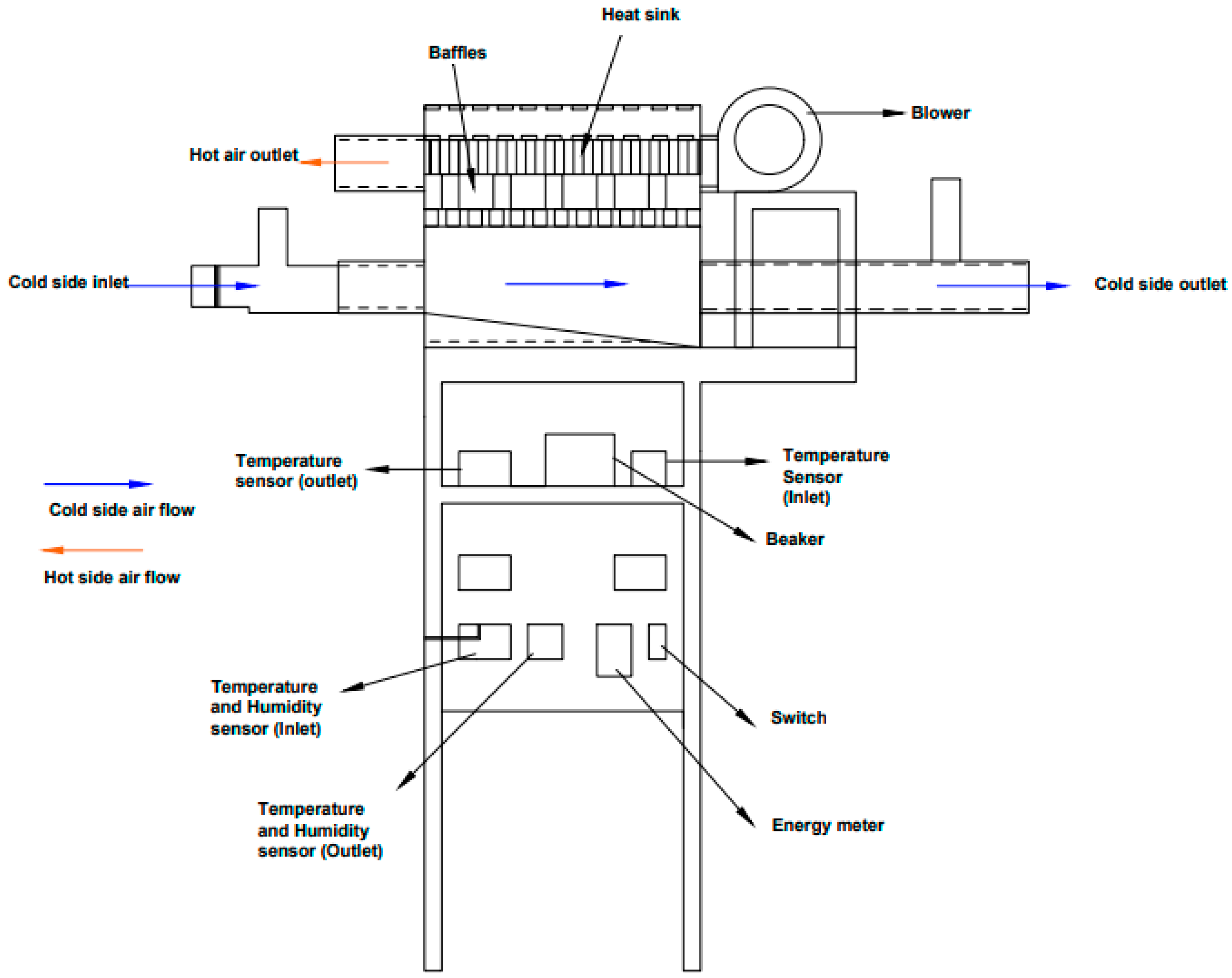
The Peltier-based dehumidifier setup consists of the Peltier plates, insulation, absorber plates with baffles, a blower, and an SMPS for the power source. The dehumidifier is monitored by a humidity sensor that holds the temperature and humidity at the inlet and outlet of the dehumidifier. A ball valve is used to direct the flow of the air. The ball valve at the top is used to control the airflow and to find the mass flow rate of the air that enters the humidifier. The duct is made up of an acrylic sheet cut into 4 individual pieces, cut into dimensions, and stuck together to form a duct. The dimensions of the duct are 60 cm × 15 cm × 30 cm on the longer side, with an inclination given to collect the condensed/dehumidified water. For the hot side on the upper half of the duct, one end is left open to release the dissipated heat into the atmosphere. There are two temperature and humidity measuring devices placed at the inlet and the outlet of the lower half of the duct (cold side). The experimental setup is schematized in
Figure 1.
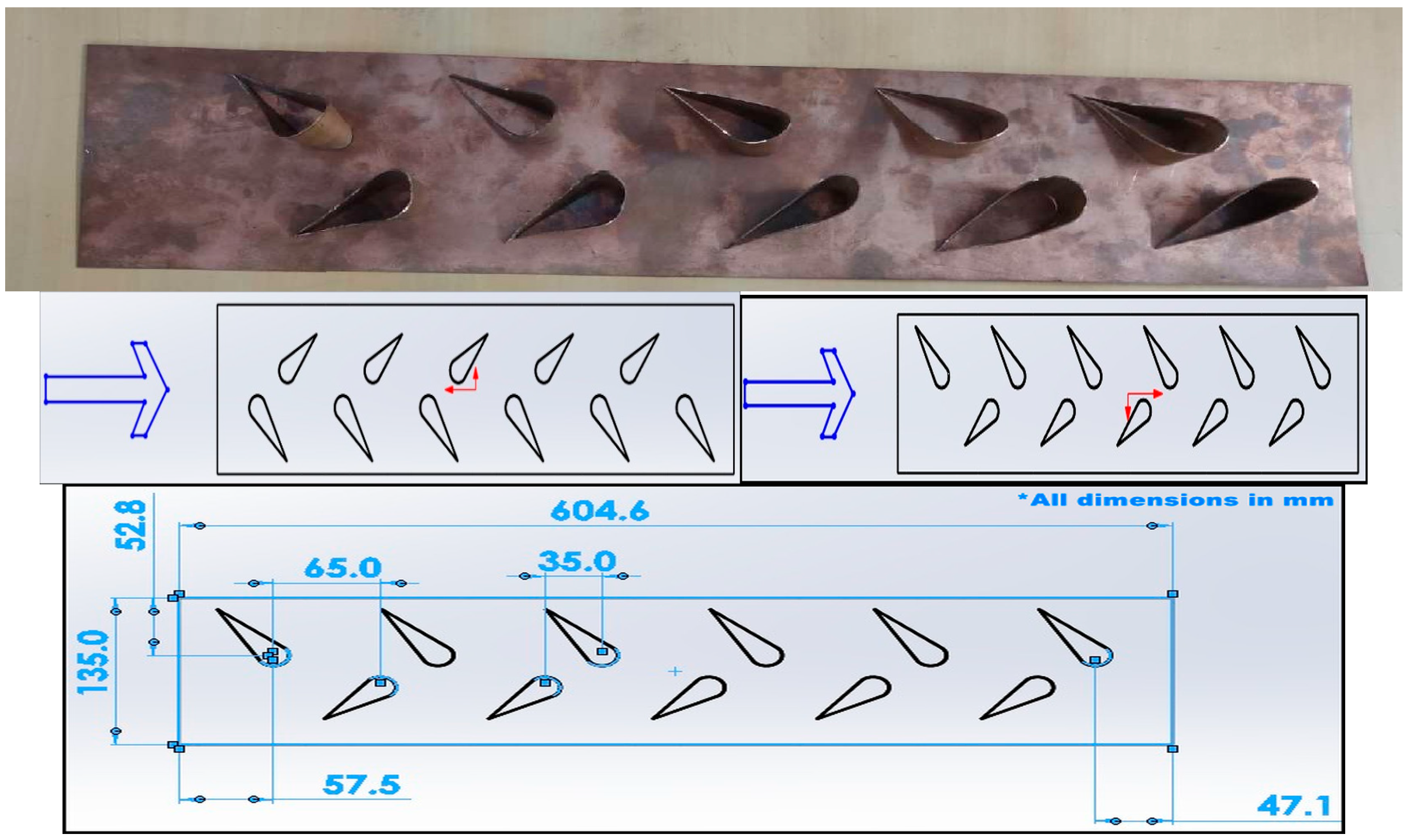
A copper plate fitted with baffles was taken as our project work for this experimental setup. The baffle was seen in the shape of an airfoil, called airfoil-shaped turbulators or airfoil-shaped baffles. Two configurations were attempted: in configuration 1, the baffles face toward the airflow, as shown in
Figure 2, and in configuration 2, the baffles face in opposite directions. These copper plates fitted with baffles are fitted onto the hot side to extract more heat from the hot side. This allows the cold side to become cooler faster, increasing the heat transfer rates on the hot side.
Figure 3 shows the experimental setup. Humid air enters the inlet, which is the cold side, and comes into contact with the Peltier plates and obtains cooled and condensed. The condensate falls on the floor of the duct due to gravity, and later on, the condensate flows to the edge of the duct. A water collection mechanism is implemented, and the condensed water is collected in a beaker.
Configuration 1 corresponds to the ambient air temperature, which ranges between 30 and 32 °C, whereas configuration 2 corresponds to the air condition in which the temperature of the air varies between 35 and 36 °C.
The air velocity at the inlet is measured by changing the ball valve at the inlet. The cold, dry air from the cold side of the outlet is released into the atmosphere. A blower is placed at the entry of the hot side to ensure that the heat emitted from the hot side of the Peltier from the sinks is constantly removed. The heat removed makes the Peltier cool faster because the more heat that is removed from the hot side, the cooler the cold side becomes. This makes the Peltier work constantly for a longer period of time and also protects the Peltier module. If heat is not removed properly, the heat moves onto the cold side, disrupting the condensation process and severely damaging the Peltier module. The experiment is repeated by fixing the turbulators on the hot side duct.
These copper plates fitted with the baffles are fitted onto the hot side to extract more heat from the hot side. This allows the cold side to become cooler faster, increasing the heat transfer rates for the hot side.
Figure 3 shows the experimental setup. Humid air enters the inlet, which is the cold side, comes into contact with the Peltier plates, and obtains cooled and condensed air. The condensate falls on the floor of the duct due to gravity, and later on, the condensate flows to the edge of the duct. A water collection mechanism is implemented, and the condensed water is collected in a beaker. The air velocity at the inlet is measured by changing the ball valve at the inlet. The cold, dry air from the cold side of the outlet is released into the atmosphere. A blower is placed at the entry of the hot side to ensure that the heat emitted from the hot side of the Peltier from the sinks is constantly removed. The removed heat makes the Peltier cool faster because the more heat that is removed from the hot side, the cooler the cold side becomes. This makes the Peltier work constantly for a longer period of time and also protects the Peltier module. If heat is not removed properly, the heat moves onto the cold side, disrupting the condensation process and severely damaging the Peltier module. The experiment is repeated by fixing the turbulators on the hot side duct.


