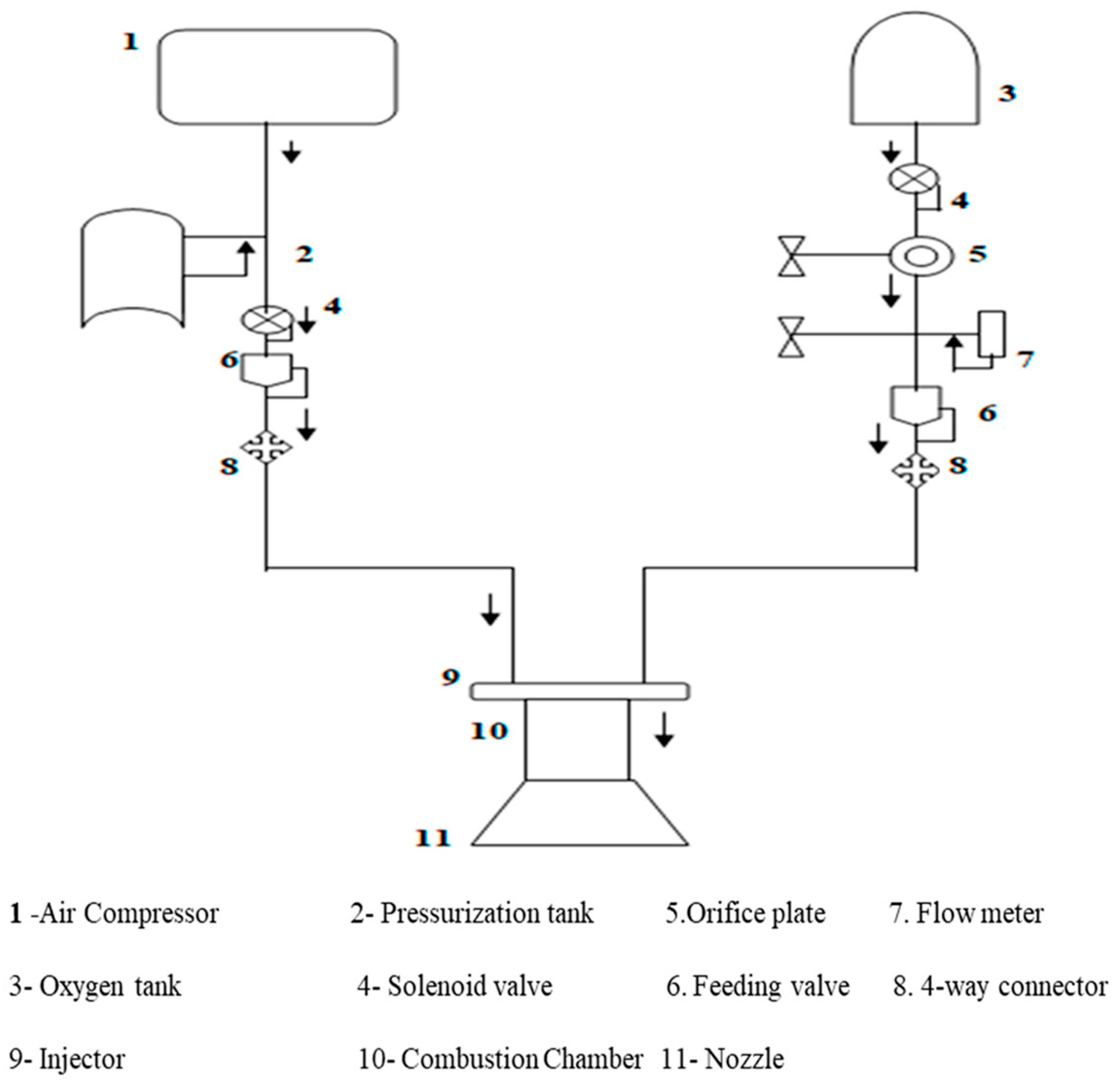
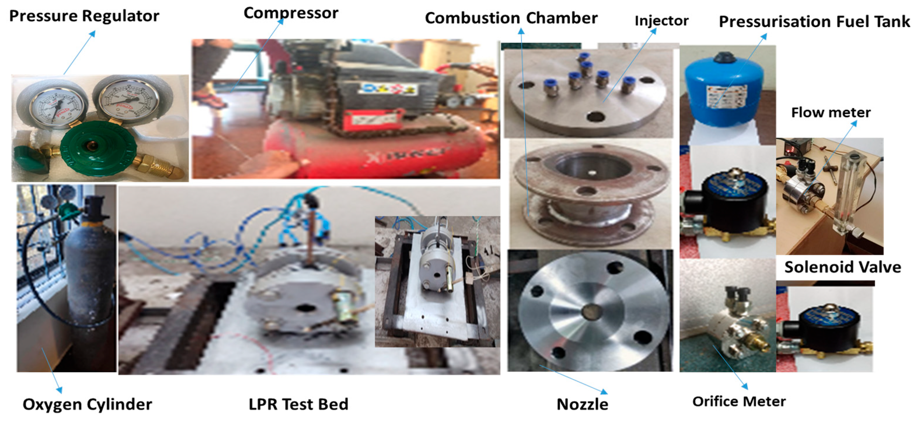
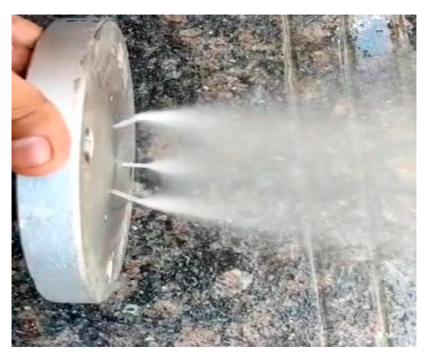
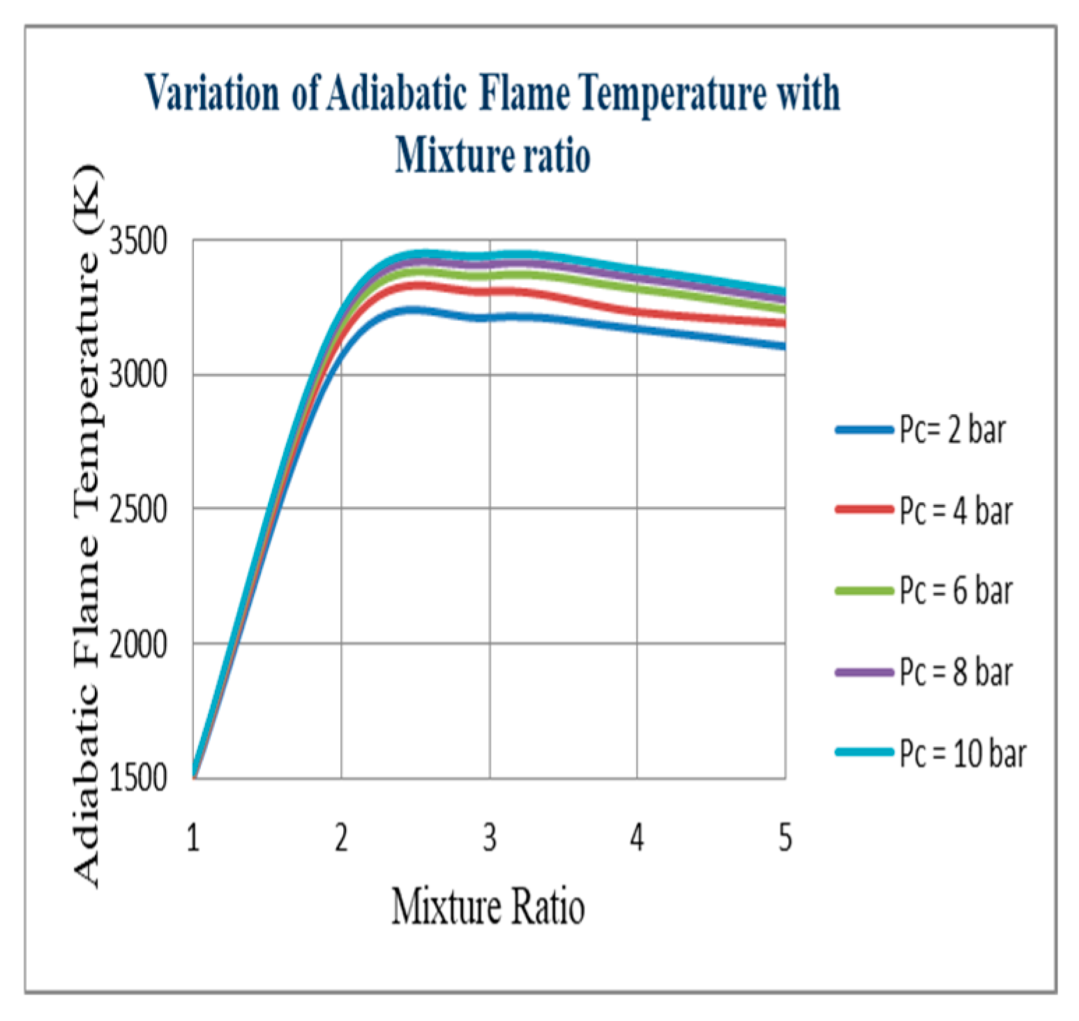
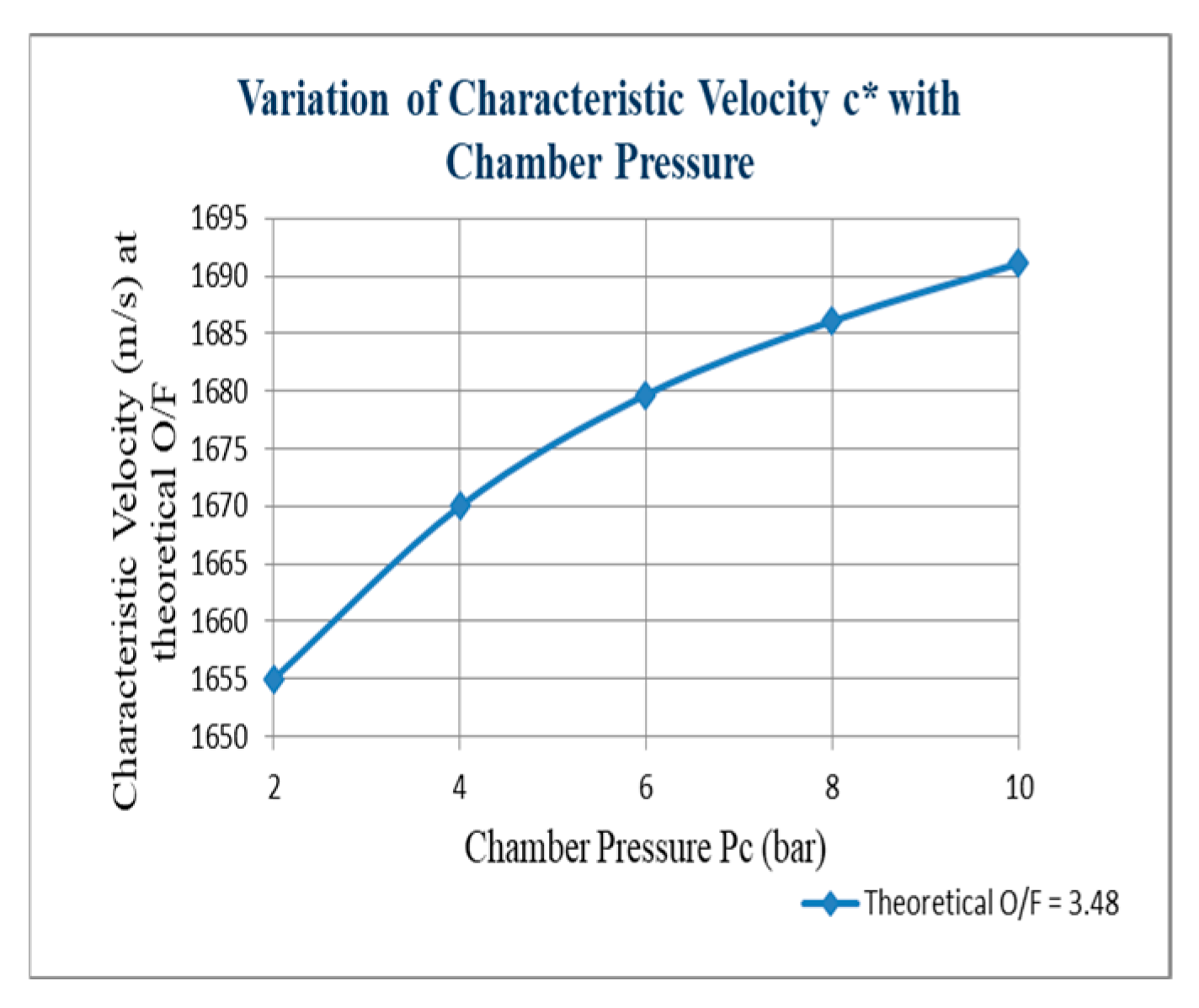
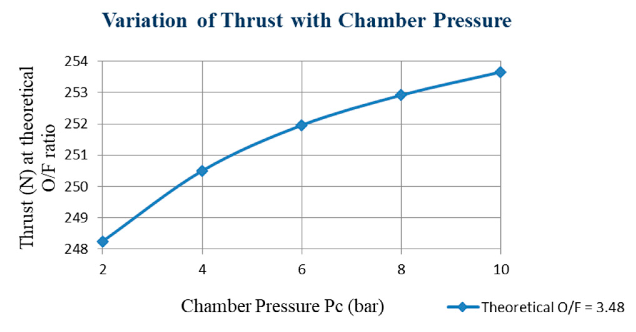
In liquid rocket engines, injection is done through tiny holes, sometimes known as “orifices”, that can be angled to allow fuel streams to transition into other fuel and oxidizer streams. This is particularly true for engines that have both propellants “liquid”, like LOX/kerosene engines. The “impingement”—the intersection of liquid streams—causes the streams to split up into a large number of tiny liquid droplets. These little droplets then burn and disappear. An “Injector” is a machine that injects oxidizer and fuel. The fuel and oxidizer must be forced into the combustion chamber to mix thoroughly, evaporate quickly, and then undergo a chemical reaction, or “burn” [
1,
2]. Over the last several decades of the 20th century, there was a notable advancement in liquid rocket propulsion. The commercialization of space will present both enormous opportunities and challenges in the coming century. To maximize the performance and adaptability of the engines that are now on the market, suggestions were made to enhance their memory and prediction for the development of liquid rocket propulsion [
3]. The operational benefit of liquid-propellant rocket engines (LREs), referred to as on-command variable thrust or thrust modulation, has been the subject of sporadic research since the late 1930s. Planetary entry and descent, space rendezvous, orbital maneuvering (including space orientation and stability), hovering, and avoiding risks during planetary landing are among the uses for adjustable LREs. Other uses have included monitoring airplane rocket engines, employing retrograde rockets to reduce vehicle acceleration or velocity, and regulating the trajectory of ballistic missile defenses. Additionally, unlike discrete throttling changes over a few chosen operating points, throttle-able LREs can continually follow the most cost-effective thrust curve in a particular scenario. The throttling behaviors are important and include the impact of altering thrust on the dynamics and mechanics of an LRE as well as challenges and problems with the throttling process itself. With an emphasis on engines, this paper offers a thorough analysis of LRE throttling [
4]. The primary technological component that has made human space exploration possible is the rocket engine. The development of the rocket engine has relied heavily on the turbo pump system, due to evolving needs and technological breakthroughs. Apart from showcasing some of the most significant engines in human history, this paper offers details on the technological advancements of the past century. This paper provides a comparative analysis of the many turbo pump configurations and a road map for comprehending the several types of turbo pump systems seen in liquid propulsion rocket engines. This page also provides an overview of the turbo pump and the numerous works that have been done on it and connected to this business over the years, which will be helpful to both novice and experienced researchers [
5]. The aircraft industry makes extensive use of liquid rocket engines due to their remarkable controllability. Designing, building, and testing a small liquid rocket engine with kerosene and gaseous oxygen was the goal of this project. The engine was built to handle a 20 bar chamber pressure. Nevertheless, during combustion, the engine could sustain a chamber pressure of up to 30 bar, which was higher than the maximum chamber pressure of 20 bar. Engine cold flow tests were conducted at chamber pressures of 4, 6, 8, and 10 bar. Following a successful conclusion, two samples were tested for simultaneous hot flow. The first feeding of the fuel and oxidizer resulted in a combustion chamber pressure of about 9 bar. Later, to increase the chamber pressure to 12.5 bar for the second test, the fuel and oxidizer feed pressures were increased simultaneously. This paper includes a detailed analysis and tabulation of each test result for each incident [
6]. The goal of this technology development procedure was to increase the degree of technological preparedness for installation on existing liquid rocket engines by taking into account every design and manufacturing phase, including material characterization, updating the design tools as needed, and performing basic single-element screening tests prior to developing, producing, and fire testing several injector configurations. The research initiatives also seek to optimize the possibilities of additive manufacturing for liquid rocket engines in the future. A more thorough approach can be performed without the need for additional certification and justification work because the design is not yet completed [
7]. The space launch system for crew exploration outside of low Earth orbit was developed by NASA. The Marshall Space Flight Center (MSFC) created a rocket engine. For the engine to run steadily, the injector must function at a high level. Some instability was displayed by the combo, which must be a major issue for this kind of injector design. They used the computational fluid dynamics (CFD) program to address this problem. The combustion, fuel mixture, and oxidizer comprise the thrust chamber assembly. Among the simulation’s results are temperature, pressure, predictions, and combustion metrics that show [
8]. German Aerospace created the liquid rocket engine injector for a state-of-the-art launcher for Europe. This injector is part of the liquid oxygen/kerosene engine. One type of injector is a coaxial injector. The material used to 3D print this injector is PLA. Furthermore, a film/laying capability built into the created injector allows the engineer to directly alter the film’s mass flow rate to the injector. Materials made of ceramic are used to resist the heat. A top-quality liquid fuel injector atomizes and blends fuel and oxidizer to provide the required thrust [
9]. A huge volume of fuel and oxidizer combination is pumped into the Formula One engine’s combustion chamber by the injector plate. The injector is inserted right before the LOX dot. The injector and Ox dome are connected by bolts, and they are subsequently fastened to the thrust chamber. The orifice arrangement is set up in a pair so that the fuel mixture and oxidizer are ejected through the impinging points in a similar doublet pattern. The fuel and oxidizer vapors mix, burn, and expel hot gases through the nozzle at impinging jets. The determined combustion may be achieved by modifying the impediment angle and the orifice plate diameter. The second injector uses baffles on the injector’s face [
10]. The concept of combustion instability in liquid propellant rocket engines is difficult for humans to comprehend and forecast because of the complicated turbulence process. Conventional techniques have increased the system’s damping by removing combustion instabilities. These approaches typically have flaws, because the underlying mechanisms have not been well investigated. Among the phenomena that have posed challenges are the creation of sprays, turbulence in multiphase flow settings, injection hydrodynamics, and droplet transport properties. Preventing the emergence of combustion instability and guaranteeing dependable operation throughout the whole combustion process are the ultimate goals of engine design. This article provides thorough advice on how to prevent the several types of combustion instabilities that might arise in rocket engines driven by liquid propellants [
11]. The dual-manifold injector’s design maintains sufficient injector pressure. Other names for this injector include dual circuit, dual orifice, and two-stage. This injector’s modest thrust improves performance and stability at larger pressure drops. Dissipative injectors in hydrodynamics operate using dynamic fluid techniques. Raising the injector velocity can enhance performance efficiency at low thrust levels, resulting in adequate stability and acceptable performance. Consent refers to the dual manifold located at the liquid/oxidizer side, where the transition between operational stability and combustion stability occurs [
12]. This prediction pertains to the impingement spray conditions in the combustion chamber. The traditional, rather than uncoupled, spray model of an injector incorporating the dual connection of jet impingement testing with the ambient gas field was studied. Compared to the uncoupled model, the more practical impingement spray specifications can simulate the coupling spray and combustion system of a liquid rocket engine [
13]. We analyzed the performance of an underdeveloped L75 liquid rocket engine using LOX/ethanol with various liquid rocket engine configurations. Here, we use the unified modeling tool—the study of design parameters that affect the performance and the dry mass of the L75 liquid rocket engine—to model the architecture of the codes [
14]. The study outlines a methodology for modeling and stability analysis. The different physical processes at a nominal regime and the components of the liquid rocket engine were linearly modeled [
15].
