1. Introduction
Poisson’s ratio defines the deformation response of the structures under loading. Based on the thermodynamic strain field considerations, its values range −1 < ν ≤ 0.5 [
1]. Most of the materials fall into the category of positive or zero Poisson’s ratio. Many natural materials such as α-cristobalite, cubic single crystal pyrite and cow teat skin, etc. [
2,
3,
4], stand out for having unique properties, including shear resistance, indentation resistance, and synclastic behavior, etc., due to the negative Poisson’s ratio structures known as auxetic meta-materials. These structures are broadly classified as Re-entrant, Chiral and Rotational rigid structures based on the geometry and deformation mechanisms.
Re-entrant honeycomb structures are honeycomb structures oriented directionally inwards resembling a bow-tie shape. The variation in mechanical modulus is primarily due to the deformation in re-entrant struts. The anisotropic behaviors of these structures depend on the geometric parameters such as strut ratio (h/l), strut thickness (t), and cell-wall angle (θ) [
5]. Gibson et al. [
6] established lateral expansion in uniaxial tensile testing in 2D re-entrant auxetic structures showing significant Poisson’s ratio variation. Apart from these parameters, auxetic cluster orientation was proven to be one of the influential factors in the Poisson’s ratio and material modulus variation, introducing a novel design concept called oriented re-entrant structures (ORS) [
7].
Khoshgoftar et al. [
8] investigated the response of a sandwich plate with a re-entrant core lattice under flexural bending tests, and found that cores exhibiting auxetic behavior demonstrated enhanced bending strength and minimized out-of-plane shear stress in comparison to structures employing conventional lattices. Liu et al. [
9] conducted an experimental study on composite re-entrant honeycomb structures under three-point bending loads, specifically examining the influence of wall thickness gradient form and relative densities. The findings indicate that the wall thickness gradient design influenced the bending failure modes of composite re-entrant honeycomb structures. The deformation of negative gradient honeycomb structures is mainly observed to be global bending deformation with discreet local compression, compared to positive gradient honeycomb structures. The bending failure load increased notably with the increase in the relative densities. Zhou et al. [
10] proposed a novel auxetic honeycomb architecture, called RE-L honeycomb, by adding an additional double V-shaped link-wall structures between two re-entrant (RE) cells, and analyzed both RE’s and RE-L’s bending behavior in a three-point bending when subjected to transverse loading. The influences of cell angle, cell wall thickness, the angle of the V-shaped link with the horizontal and the slant length of a single v-link on the bending behavior were studied. Menon et al. [
11] carried out four-point bending on auxetic cored beams following the introduction of filler materials in its voids to improve its load-bearing potential. In another study by Dutta et al. [
12], the bending characteristics of ORS auxetic beams and their deflection were studied. It was observed that ORS45 showed the least deformation.
In this work, honeycomb and re-entrant structured beams consisting of bounded frames and clusters of re-entrant structures oriented at different angles were modeled, and their transverse loading was simulated using numerical methods. Various characteristics of the different beams, like the deformations and strains, are here analyzed and compared.
2. Modeling and Finite Element Analysis
The modeling of the honeycomb beam and the oriented re-entrant structures (ORS) is performed using ABAQUS 6.14. The unit cell structure of re-entrant honeycomb is constructed as shown in
Figure 1, with a cell angle of 32° and a rib thickness of 1 mm. The horizontal length and slant length are 16.39 mm and 8.25 mm, respectively. These replicated cells constitute a cluster of auxetic structures within a frame as shown in
Figure 2The re-entrant beams are designed with orientation angles of 0° (ORS0), 45° (ORS45) and 90° (ORS90), as seen in
Figure 3. The ultimate configurations of ORS0, ORS45, and ORS90 are obtained by rotating a cluster of re-entrant cells at the respective angles and positioning it within a bounded frame measuring 326 mm in length, 64 mm in width, and 6 mm in thickness. The depth of the structures is 10 mm each. The dimensions are set as the same for all the beams to maintain uniformity and avoid errors.
These models are subjected to finite element analysis using ANSYS 2023 R1. The FEA models of the beams are developed using a material with density 2.7 kg/m3, Young’s modulus 68 GPa and Poisson’s ratio 0.36. All the beam models are meshed with elements of size 2 mm. These specimens are subjected to compressive three-point bending analysis with 1000 N lateral load. The loading conditions are also kept constant to maintain uniformity and minimize inaccuracies.
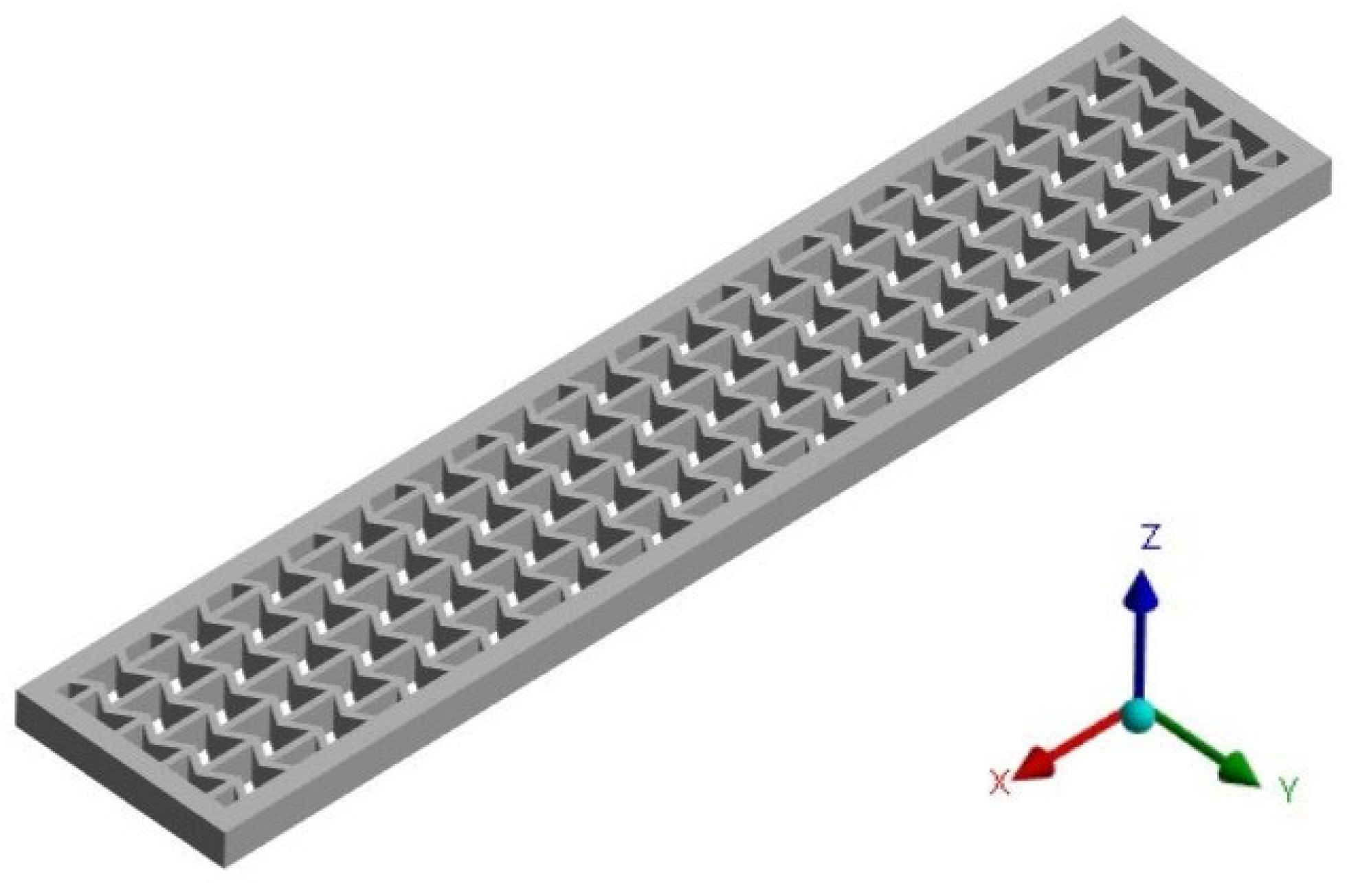
In conformity with the global coordinate system, the positioning of the beams conforms precisely to the illustrative representation depicted in
Figure 4.
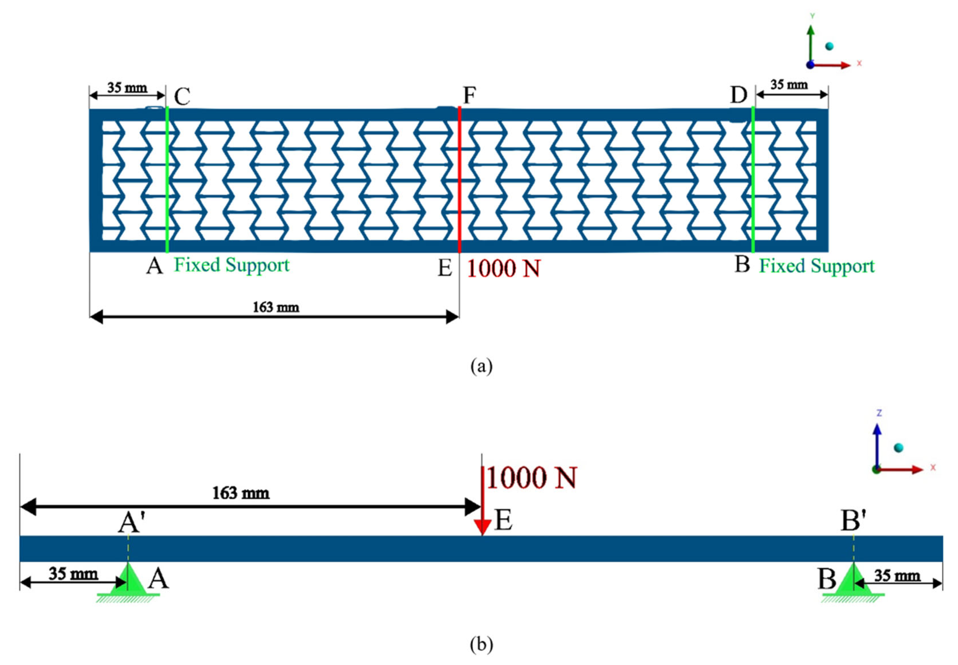
A force of 1000 N is applied along the center line of all the beams at EF, as shown in
Figure 5. The force is exerted in the direction of negative
z-axis. Fixed supports are provided along the beams at two lines AC and BD, both 35 mm apart from each of the respective ends, as shown in
Figure 5.
The characteristics taken into consideration for the analysis are directional deformation along the
z-axis and normal elastic strain along the
x-axis. These characteristics were analyzed on edge AB, i.e., the bottom fiber, and on the edge A′B′, i.e., the top fiber (refer
Figure 5b). The lengths of both edges AB and A′B′ are equal to 256 mm.
3. Results and Discussion
In the resultant graphs shown in
Figure 6, 0 mm denotes AA′ and 256 mm denotes BB’ (refer
Figure 5b). The graphs in
Figure 6 focus on the resulting mechanical behaviors of the beams spanning from 70 mm to 180 mm.
The deformations along the z-axis in both edges AB and A′B′ exhibit similarities in both pattern and magnitude. Notably, the directional deformation is minimal toward the fixed ends, and gradually escalates toward the beam’s center. In both AB and A′B′, the least deformation among the re-entrant beams is observed in ORS45, followed by ORS90 and ORS0. The honeycomb beam also exhibits a deformation that is very close to that of ORS0.
On edge AB, at the fixed ends, the normal strain along x-axis (εxx) is observed to be at its minimum, while towards the midpoint of AB, the strain along the x-axis (εxx) becomes progressively positive. The opposite trend is discernible along the edge A′B′. In both edges of re-entrant beams, the least strain in magnitude is noted in ORS45, succeeded by ORS90 and ORS0.
In
Figure 6a,b, the honeycomb beam exhibits behaviors very close to that of an ORS0 beam. The homogeneous beam shows very significant variation from the remaining re-entrant beams. It gives small values for deformation and strains.
4. Conclusions
Oriented re-entrant structured (ORS) beams with orientations at 0°, 45° and 90° and a honeycomb beam were modeled using ABAQUS, and they were subjected to three-point bending using Finite Element Analysis to find out the best-performing re-entrant beam. A force of 1000 N was used to perform the bending.
Directional deformations and normal strain along the
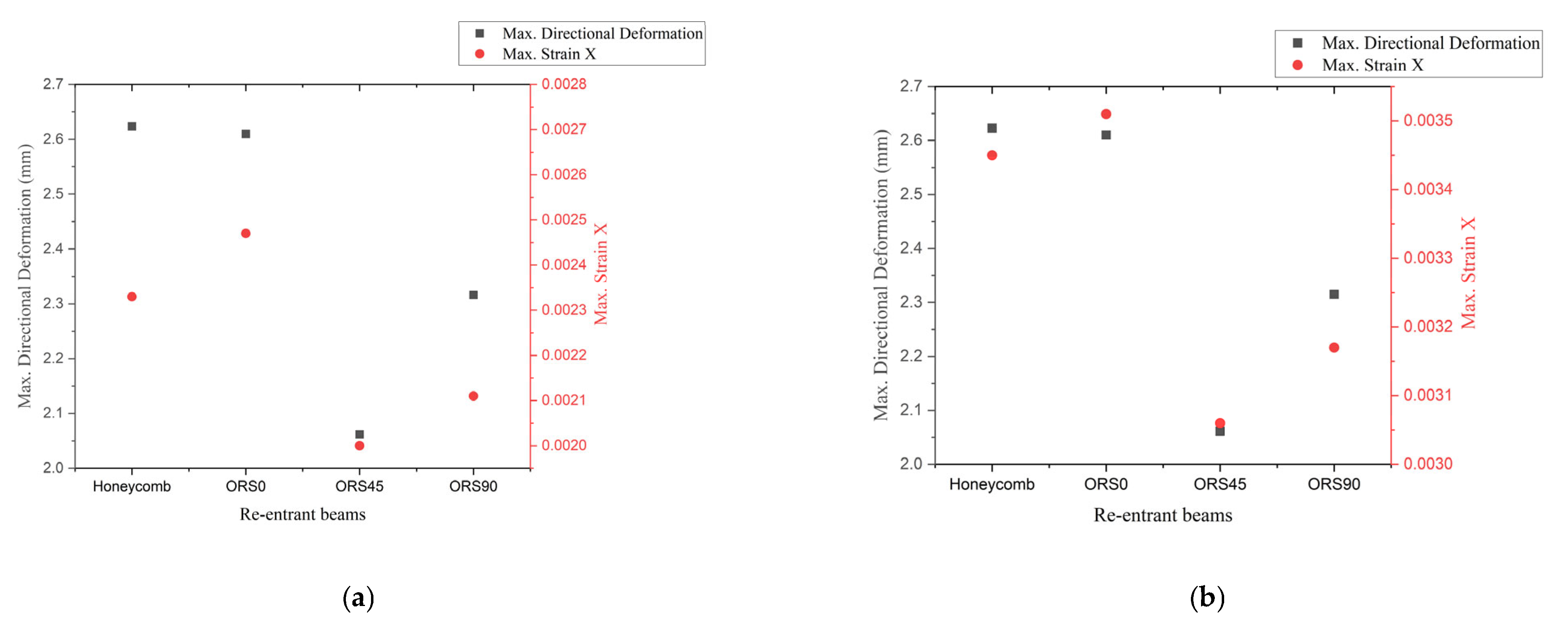
x-axis have been observed on the top edge (A′B′) and bottom edge (AB) of conventional honeycomb, ORS0, ORS45 and ORS90 beams. Among the re-entrant beams, all the afore-mentioned properties were observed as the lowest in ORS45, followed by ORS90 and ORS0. The honeycomb beam showed the least change in values, and a solid homogeneous material exhibited a substantial variation from the property values exhibited by all the other re-entrant structures. Hence, ORS45 is the best-performing beam with a low mass density.
Figure 7 clearly depicts the greater performance of ORS45 over other beams with lower structural densities.
Author Contributions
Conceptualization, M.P.H.; methodology, N.S.; software N.S.; validation, N.S. and M.P.H.; formal analysis, N.S. and M.P.H.; investigation, N.S.; resources, M.P.H.; data curation, N.S. and M.P.H.; writing—original draft preparation, N.S.; writing—review and editing, M.P.H.; visualization, N.S.; supervision, M.P.H.; project administration, M.P.H. All authors have read and agreed to the published version of the manuscript.
Funding
This research received no external funding.
Institutional Review Board Statement
Not applicable.
Informed Consent Statement
Not applicable.
Data Availability Statement
The data presented in this study are available upon request from the corresponding author.
Acknowledgments
The authors are deeply grateful to Mata Amritanandamayi Devi, Chancellor, Amrita Vishwa Vidyapeetham, for enlightening us and enabling our research activities.
Conflicts of Interest
The authors declare no conflicts of interest.
References
- Jiang, H.; Ziegler, H.; Zhang, Z.; Atre, S.; Chen, Y. Bending behavior of 3D printed mechanically robust tubular lattice metamaterials. Addit. Manuf. 2022, 50, 102565. [Google Scholar] [CrossRef]
- Yeganeh-Haeri, A.; Weidner, D.J.; Parise, J.B. Elasticity of α-Cristobalite: A Silicon Dioxide with a Negative Poisson’s Ratio. Science 1992, 257, 650–652. [Google Scholar] [CrossRef] [PubMed]
- Baughman, R.H.; Shacklette, J.M.; Zakhidov, A.A.; Stafström, S. Negative Poisson’s ratios as a common feature of cubic metals. Nature 1998, 392, 362–365. [Google Scholar] [CrossRef]
- Lees, C.; Vincent, J.F.; Hillerton, J.E. Poisson’s ratio in skin. Biomed. Mater. Eng. 1991, 1, 19–23. [Google Scholar] [CrossRef] [PubMed]
- Yang, W.; Li, Z.; Shi, W.; Xie, B.; Yang, M. Review on auxetic materials. J. Mater. Sci. 2004, 39, 3269–3279. [Google Scholar] [CrossRef]
- Gibson, L.J.; Ashby, M.F.; Schajer, G.S.; Robertson, C.I. The Mechanics of Two-Dimensional Cellular Materials. Proc. R. Soc. Lond. Ser. A 1982, 382, 25–42. [Google Scholar] [CrossRef]
- Menon, H.G.; Dutta, S.; Krishnan, A.; Hariprasad, M.P.; Shankar, B. Proposed auxetic cluster designs for lightweight structural beams with improved load bearing capacity. Eng. Struct. 2022, 260, 114241. [Google Scholar] [CrossRef]
- Khoshgoftar, M.J.; Barkhordari, A.; Limuti, M.; Buccino, F.; Vergani, L.; Mirzaali, M.J. Bending analysis of sandwich panel composite with a re-entrant lattice core using zig-zag theory. Sci. Rep. 2022, 12, 15796. [Google Scholar] [CrossRef] [PubMed]
- Liu, Z.; Liu, J.; Zhang, M.; Liu, J.; Huang, W. Study of three-point bending behaviors of composite sandwich structure with re-entrant honeycomb cores. Polym. Compos. 2023, 44, 673–684. [Google Scholar] [CrossRef]
- Zhou, Y.; Pan, Y.; Chen, L.; Gao, Q.; Sun, B. Study on the Bending Behaviors of a Novel Flexible Re-Entrant Honeycomb. J. Eng. Mater. Technol. 2023, 145, 041006. [Google Scholar] [CrossRef]
- Menon, H.G.; Dutta, S.; Hariprasad, M.P.; Shankar, B. Investigation on Deflection Characteristics of Auxetic Beam Structures Using FEM. In Proceedings of the International Conference on Future Technologies in Manufacturing, Automation, Design and Energy, Karaikal, India, 28–30 December 2020. [Google Scholar] [CrossRef]
- Dutta, S.; Menon, H.G.; Hariprasad, M.P.; Krishnan, A.; Shankar, B. Study of auxetic beams under bending: A finite element approach. Mater. Today Proc. 2019, 46, 9782–9787. [Google Scholar] [CrossRef]
| Disclaimer/Publisher’s Note: The statements, opinions and data contained in all publications are solely those of the individual author(s) and contributor(s) and not of MDPI and/or the editor(s). MDPI and/or the editor(s) disclaim responsibility for any injury to people or property resulting from any ideas, methods, instructions or products referred to in the content. |
© 2025 by the authors. Licensee MDPI, Basel, Switzerland. This article is an open access article distributed under the terms and conditions of the Creative Commons Attribution (CC BY) license (https://creativecommons.org/licenses/by/4.0/).


