Abstract
Friction stir welding (FSW) is a novel welding technique that produces a solid-state weld by generating frictional heat and plastic deformation at the weld spot with a revolving, non-consumable welding tool. Despite processing a wide range of industrial materials, FSW has concentrated on welding aluminum and its alloys because of its high strength-to-weight ratio and uses in the shipbuilding, aerospace, and other fabrication industries. Important FSW process factors that determine the mechanical qualities of the weldment are the tool tilt angle, tool traverse feed, tool pin profile, tool rotational speed (TRS), tool traverse speed (TTS), tool pin profile (TPP), and shoulder plunge depth. Variations in the required process parameters cause defects, which lower the weld quality of FSWed aluminum alloys (AA). Therefore, keeping an eye on and managing the FSW process is crucial to preserving the caliber of the weld joints. The current study aims to investigate the changes in the mechanical characteristics and microstructure of the FSWed AA5052-H111 and AA6061-T6 joints. To perform the FSW experiments, we varied TRS, TTS, and TPP on plates that were 5 mm thick and had a butt joint structure. Following welding, the microstructure of the weld zones was examined to observe how the grains had changed. The joint’s tensile strength reached a maximum of 227 MPa for the square-shaped TPP, and the micro-Vickers hardness test results showed a maximum of 102 HV at the weld nugget zone (WNZ).
1. Introduction
FSW is a popular pressure welding technique for combining light metals and alloys with several benefits. It is possible to weld many hundreds of meters with a standard non-consumable tool. Numerous industries use FSW, including shipbuilding, marine, aircraft, automotive, construction, furniture, and electrical equipment. Welding big panels, vehicle bodies, train bodies, floor panels, and marine structural frames are a few examples of industrial applications. Many researchers are working on FSW of different similar and dissimilar AAs. Yazdipour et al. [1] looked at the mechanical characteristics and microstructural traits of two distinct welding processes: FSW and Metal Inert Gas (MIG). They employed AA5083-H321, which is 5 mm thick, for their investigation. Additionally, they have examined the mechanical characteristics of the weld, such as its tensile strength and hardness. Due to the solidification process, they examined the microstructure of both welds and discovered fine equiaxed grains in the stir zone of the FSWed samples, as well as equiaxed dendrites in the MIG-welded specimens. Experiments were performed on the FSW of AA5083-H321 by Jitender Kundu et al. [2]. They have optimized the welding process settings to get the highest possible joint strength. To optimize the excellent weld process parameters, they have experimented with varying tool traverse speeds of 16, 28, and 40 mm/min and tool rotational speeds of 500, 950, and 1400 RPM.
Tronci et al. [3] examined the mechanical and microstructural properties of friction stir welded 1 mm thick AA5182-H111 and AA5083-H111 alloys. Conical shoulders with an 8° angle and a 10 mm shoulder diameter, rolled shoulder tools with a 14 mm shoulder diameter, and flat shoulder tools with a 14 mm shoulder diameter are the five tool pin profiles that are employed in their study. The impact of FSW parameters on the mechanical and microstructural characteristics of 5083-H111 plate, which is 6 mm thick, has been examined by Birol et al. [4]. Threaded cylinders with a pin diameter of 7.7 mm and triangular pins with a pin width of 6.2 mm were the TPPs utilized in their investigation. A defect-free weld with a UTS value of 315 MPa was created by the triangular tool pin profile weldments made at a traverse speed of 80 mm/min.
The microstructural and mechanical properties of a 13 mm-thick AA-6061-T6 plate were examined by Fahimpour et al. [5] during the FSW and TIG welding. In the TIG welding process, the authors have seen dendritic structures grow in the weld zone, while in the FSW process, they have seen a drop in grain size. Rohit Kumar et al. [6] investigated how TRS and TTF affected the FSW of AA6061-O, which is 6 mm thick. According to the authors, the sample welded at 355 rpm and 400 mm/min had high UTS values, and the UTS is directly proportional to the welding speed.
Jamshidi Aval. et al. [7] have investigated how FSWed AA6061 weldments’ mechanical properties are affected by natural aging. The authors concluded that the mechanical properties of the heat-treatable aluminum alloy weldment significantly improved with natural aging. Dehghani et al. [8] investigated the mechanical and microstructural characteristics of the FSWed AA7075-O joint. According to the authors’ analysis of the mechanical characteristics of the weldments, precipitate distribution, not grain size, determines the hardness of heat-treatable aluminum alloys. The investigators have also discovered that the precipitates in the heat-affected zone (HAZ) are comparatively coarser than those in the SZ.
Moradi et al. [9] investigated the evolution of microstructure and crystallographic texture in dissimilar FSWed AA2024 and AA6061 joints. The results showed grain refinement in the stir zone caused by continuous and discontinuous recrystallization. They discovered that the grain size of the thermomechanically impacted zone (TMAZ) is substantially bigger than that of the stir zone. Sefika Kasman [10] studied how the tool shoulder and tool pin diameter ratio affect FSW. TRS, TTS, and three D/d ratio levels were used in their study. Their analysis revealed that the ideal FSW conditions for properly welding the AA6082 and AA5754 joints are 1000 rpm TRS, 100 mm/min TTS, and a D/d ratio of 4. From the literature, it was found that most studies focus on similar aluminum alloys, with limited work on dissimilar alloys. The dissimilar joining of AA5052 and AA6061, which are crucial for marine applications like ship hulls, remains largely unexplored. The literature mainly examines single parameters, with few studies addressing the combined impact of multiple factors. Hence, the present work focuses on the impact of three FSW parameters on dissimilar AA joints.
2. Experimental Details
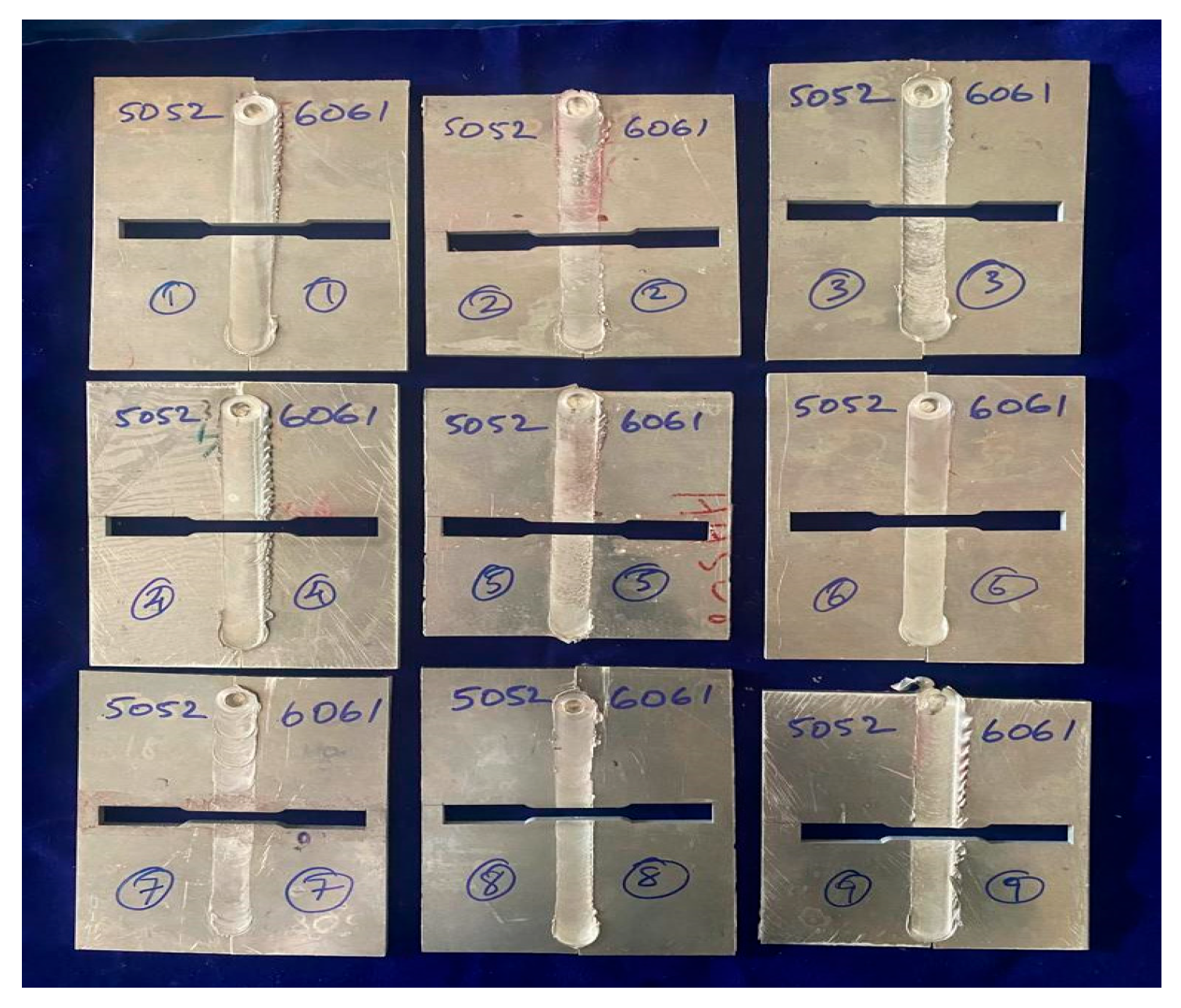
The AA5052-H111 and AA6061-T6 dissimilar plates of 150 × 50 × 5 mm (l × b × t) size were employed in the experimental investigation. A Creative Automation FSW machine was used for FSW, and the machine has a 1.5 horsepower motor, a spindle speed of 3000 rpm, and a load capacity of 300 kN. The FSW experiments are formulated using Taguchi L9 analysis, which has three input parameters: tool rotational speed (TRS), tool traverse speed (TTS), and tool pin profile (TPP). The limits of the parameters chosen are given in Table 1, and these values were taken from the literature as well as from initial trials. The samples welded from FSW are given in Figure 1.

Table 1.
Welding parameter limits.
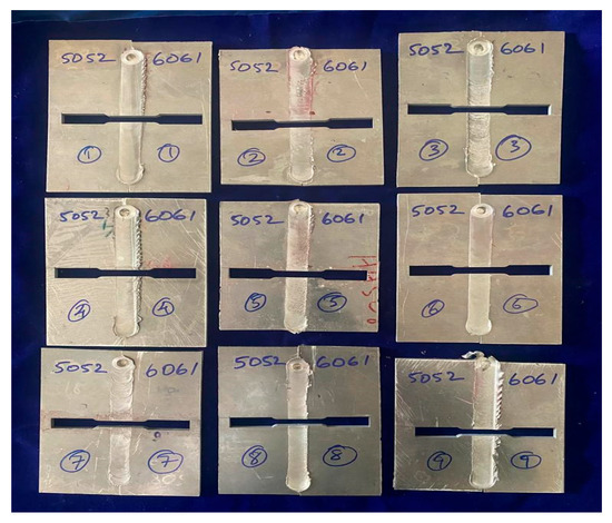
Figure 1.
Welded plates from FSW.
The samples were welded using the determined input parameters. The samples to find the tensile strength of the welds are taken out along the transverse direction using Wire Electric Discharge Machining (WEDM) as per ASTM-E8/E8M-24 standards [11] and the Figure 2 shows the Photo of the extracted tensile samples with dimension details.
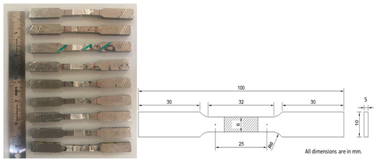
Figure 2.
Tensile specimens along with dimension details.
The ultimate tensile strength (UTS) values of the extracted tensile samples were determined by using a universal testing machine (UTM). Tensile tests were carried out at a crosshead rate of 1 mm/min using a UTM (Blue Star Engineering & Electronics Ltd., model LDW50, Mumbai, Maharashtra, India). Table 2 presents the experimental design and findings obtained.
Table 2.
Tensile test results of the FSWed weldments.
3. Results and Discussion
3.1. Microstructure Analysis
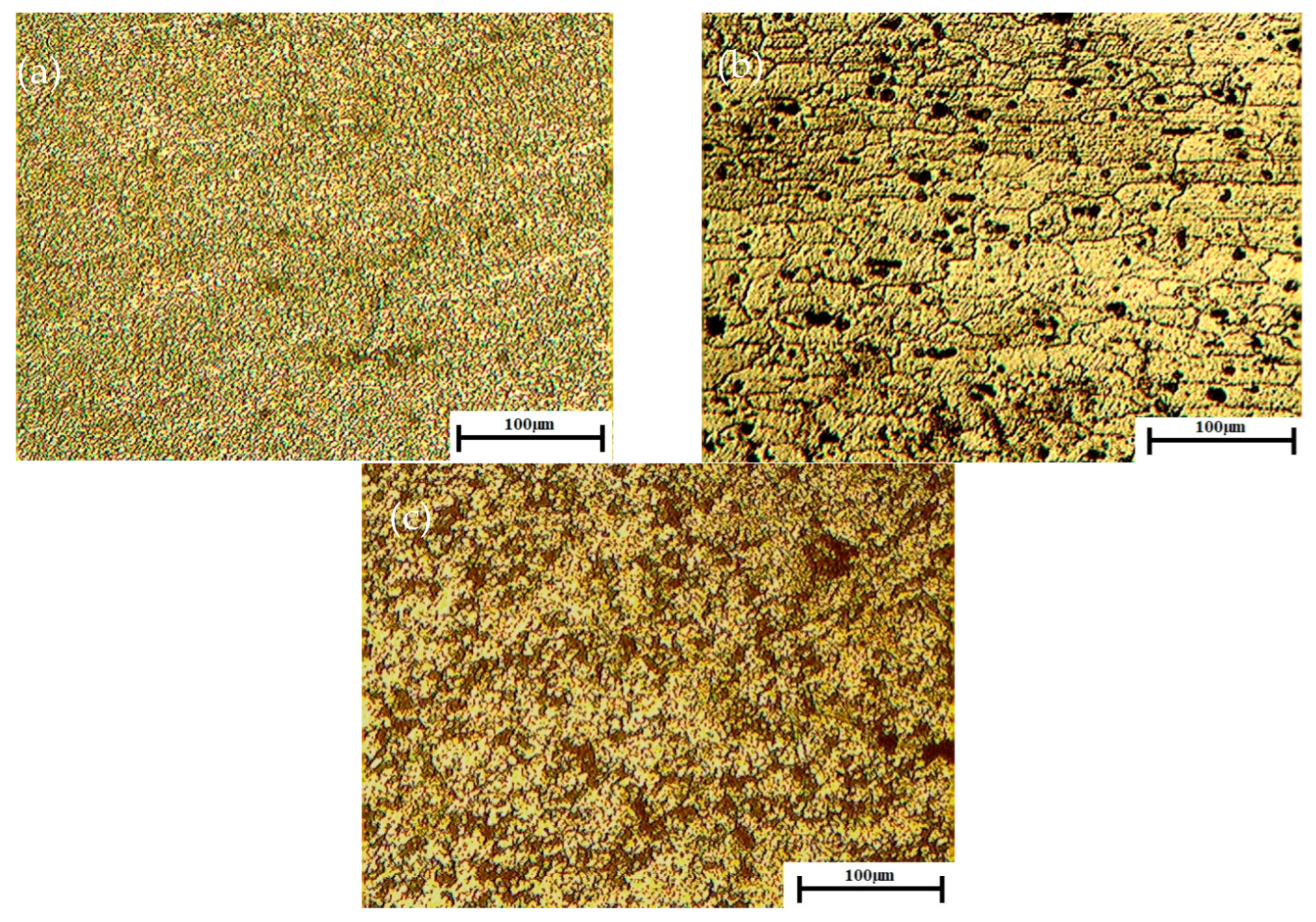
Using an optical microscope (OM) set to 500×, the microstructure of the weldments is captured. The extraction of the optical microstructure sample follows the transverse direction of the weldments. The microstructure of the polished sample is revealed by etching it with Keller’s reagent. After the etched sample is put under an optical microscope, an image of the optical microstructure is taken.
Figure 3 displays the microstructure image that was retrieved from the OM. Figure 3a,b display the OM images of the base metals AA5052 and AA6061, respectively. Figure 3c displays the OM picture of the weld nugget zone (WNZ) of the weldments. When the OM images are compared, the base metal’s grains are very large, while the weld nugget’s grains are very small. This is because the weld nugget’s stirring action from FSW has produced dynamic recrystallization. It is also seen that the larger precipitates on the base metal have fractured and are dispersed throughout the WNZ. The decrease of grain size and the dispersion of strengthening precipitate across the WNZ increases the WNZ’s strength over the base metal [12]. This is the primary cause of failure to happen outside the WNZ.
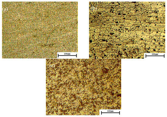
Figure 3.
Optical Microstructure (a) Base Metal AA5052-H111 (b) Base Metal AA6061-T6. (c) Weld Nugget.
3.2. Analysis of Tensile Strength
The experimental data were loaded into Minitab v.19 software for further analysis of the effect of input parameters on UTS. The welded sample has a maximum UTS of 227 MPa and a joint efficiency of 68.73%. The failure occurred in the heat-affected area of the AA6061-T6 side. This resulted from the disintegration of Mg2Si strengthening precipitates at the HAZ. The strengthening precipitates dissolve because of the enhanced heat flow at the HAZ. Heat flow at the HAZ causes grain size to grow in the WNZ. According to the Hall-Petch relationship, increasing grain size reduces alloy strength.
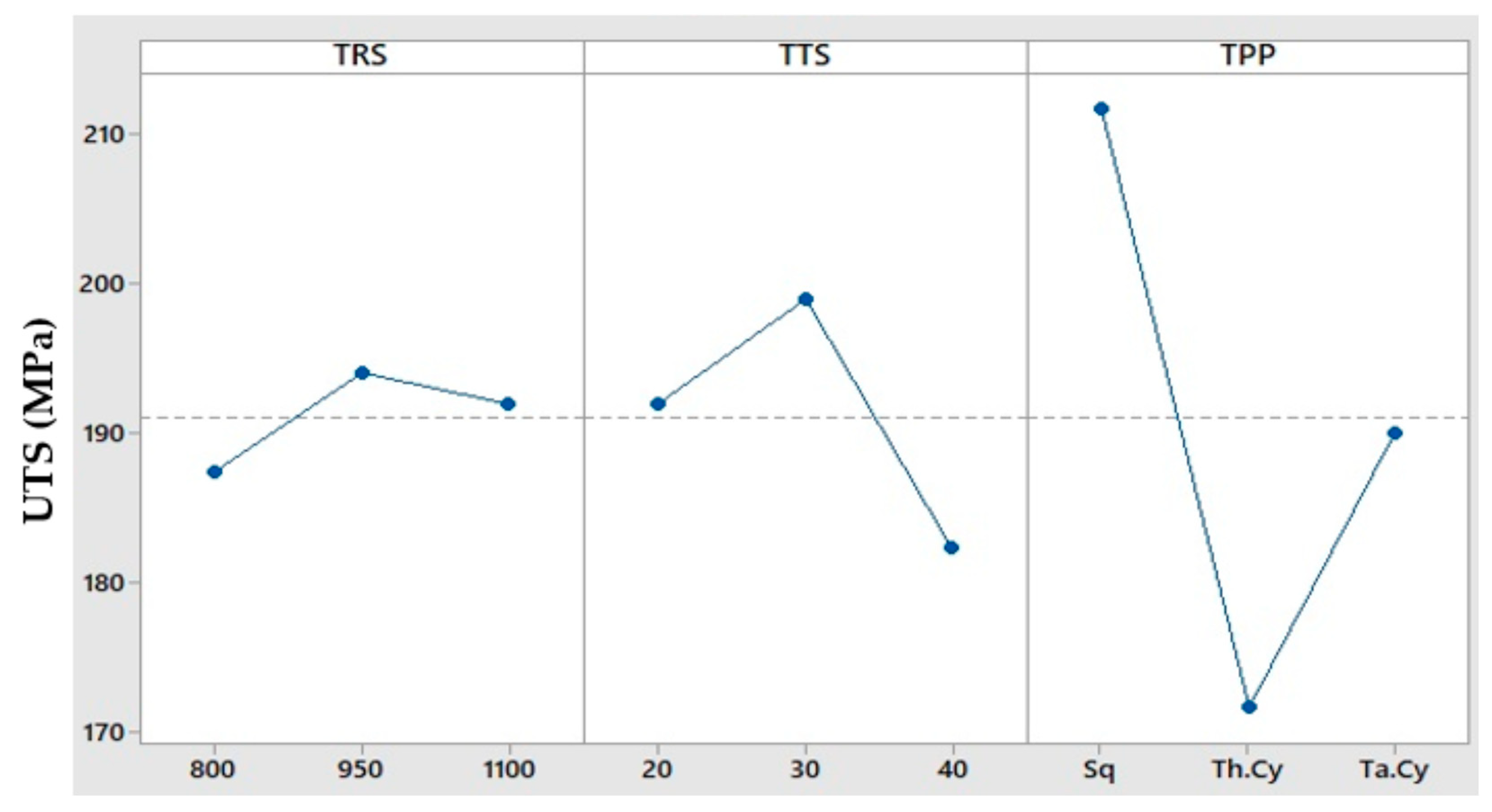
From Figure 4, it is found that when the TRS is low, insufficient heat is generated, which causes poor material plasticization, a lesser stir zone’s hardness, and higher heat causes grain coarsening due to more heat input at higher TRS [13]. Hence, medium TRS is good for getting a better UTS value since it creates balanced heat with uniform mixing of both materials. In the same way, the mid value of TTS gives balanced heat input and controlled cooling with fine grains for better UTS compared with the other 2 TTS settings. From 3 TPPs, the square pin produced a good UTS value due to its flat, sharp edges, which caused enhancement in material flow and plastic deformation, generating more heat, good stirring action, etc. Moreover, the threaded cylinder pin improves material mixing, has a higher heat input, and produces stronger welds, making them more effective for thicker and stronger materials than the taper cylinder pin during the FSW process, since the threads enhance the vertical flow and material stirring. Overall, the welded samples prove that the optimum welding parameters selected from this study are 950 rpm TRS, 30 mm/min TTS with straight square as TPP for getting the maximum UTS value.
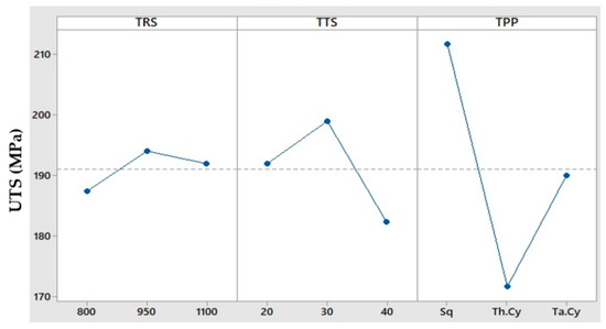
Figure 4.
Main effects plot for tensile strength of FSWed weldments.
3.3. Hardness Survey
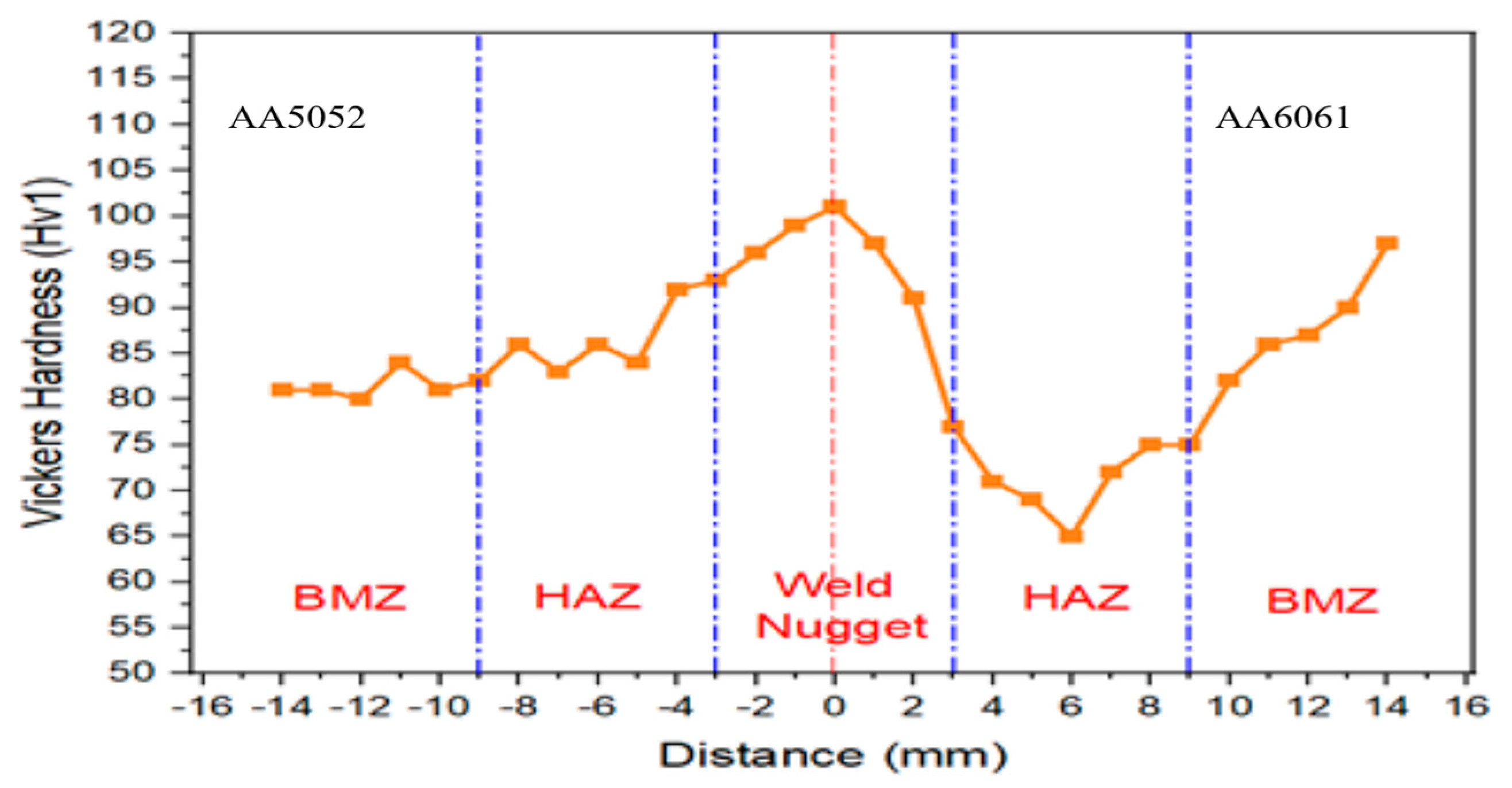
The FSW sample from experiment number 8, which had a higher UTS value, was taken to test for hardness. The hardness values are measured using a diamond indenter and a Vickers microhardness tester. A 1 kg load is applied for 30 s of dwell time during the tests. A hardness survey is conducted at each of the welded samples’ zones to find out how hardness values vary across different zones. The results are displayed on a graph in Figure 5, with the WNZ exhibiting the highest hardness values. The stirring motion brought on by the tool pin profile is the cause of the dynamic recrystallization that took place at the WNZ. The zone that is influenced by heat also exhibits the lowest hardness value. Because of the strong heat flow at that HAZ during the FSW process, strengthening precipitates at the WNZ have dissolved, and their grain size has increased [14]. Because of its low hardness rating, the HAZ is the softest zone of all, which is why failures do not happen there.
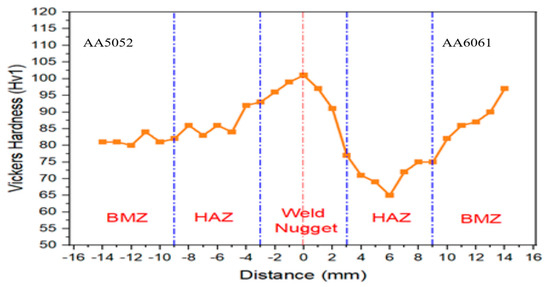
Figure 5.
Hardness Survey on various zones of the weldment.
4. Conclusions
The FSW of AA5052 and AA6061 was completed satisfactorily, and there were no significant weld flaws. The following are the findings from the study:
We may infer from the optical microscopy microstructure images that the retreating side’s HAZ is the weakest area in the friction stir welded sample due to the grain growth that took place there. In contrast to the lower base metal tensile strength, the FSW of AA5052 and AA6061 yielded a tensile strength of 227 MPa with a 69% joint efficiency. At the retreating side’s HAZ, the failure took place. The breakdown of Mg2Si precipitates at the retreating side’s HAZ produced a very low hardness value, but the presence of fine equiaxed recrystallized grains brought about by the tool pin’s proper stirring produced high hardness values in the WNZ.
Author Contributions
Conceptualization, supervision, and review, J.K.; methodology, S.K.M., S.N. and S.P.P.; investigation, writing—original draft preparation, S.N. All authors have read and agreed to the published version of the manuscript.
Funding
This research received no external funding.
Institutional Review Board Statement
Not applicable.
Informed Consent Statement
Not applicable.
Data Availability Statement
No data were used for the research described in the article.
Conflicts of Interest
The authors declare no conflicts of interest.
References
- Yazidipour, A.R.; Shafiei, M.; Jamshidi Aval, H. An investigation of the microstructures and properties of metal inert gas and friction stir welds in aluminum alloy 5083. Sadhana 2011, 36, 505–514. [Google Scholar] [CrossRef]
- Kundu, J.; Singh, H. Friction stir welding of AA5083 aluminium alloy: Multi-response optimization using Taguchi-based grey relational analysis. Adv. Mech. Eng. 2016, 8, 1–10. [Google Scholar] [CrossRef]
- Tronci, A.; McKenzie, R.; Leal, R.M.; Rodriigues, D.M. Microstructural and mechanical characterization of 5xxx-H111 friction stir welded tailored blanks. Sci. Technol. Weld. Join. 2011, 16, 433–439. [Google Scholar] [CrossRef]
- Birol, Y.; Kasman, S. Effect of welding parameters on microstructure and mechanical properties of friction stir welded EN AW 5083 H111 plats. Mater. Sci. Technol. 2013, 29, 1354–1362. [Google Scholar] [CrossRef]
- Fahimpour, V.; Sadrnezhaad, S.K.; Karimzadeh, F. Microstructure and mechanical property change during FSW and GTAW of Al6061 alloy. Metall. Mater. Trans. A 2013, 44, 2187–2195. [Google Scholar] [CrossRef]
- Kumar, R.; Singh, R.K.R.; Bajpai, A.K. Mechanical properties of friction stir welded 6061 aluminium alloy. Int. J. Eng. Res. Technol. 2013, 2, 74–80. [Google Scholar]
- Jamshidi Aval, H.; Serajzadeh, S. A study on natural aging behavior and mechanical properties of friction stir welded AA6061-T6 plates. Int. J. Adv. Manuf. Technol. 2014, 71, 933–941. [Google Scholar] [CrossRef]
- Dehghani, K.; Ghorbani, R.; Soltanipoor, A.R. Microstructural evolution and mechanical properties during the friction stir welding of 7075-O aluminum alloy. Int. J. Adv. Manuf. Technol. 2015, 77, 1671–1679. [Google Scholar] [CrossRef]
- Moradi, M.M.; Aval, H.J.; Jamaati, R.; Amirkhanlou, S.; Ji, S. Microstructure and texture evaluation of friction stir welded dissimilar aluminum alloys: AA2024 and AA6061. J. Manuf. Process. 2018, 32, 1–10. [Google Scholar] [CrossRef]
- Kasman, S. Multi-response optimization using the Taguchi-based grey relational analysis: A case study for dissimilar friction stir butt welding of AA6082-T6/AA5754-H111. Int. J. Adv. Manuf. Technol. 2013, 68, 795–804. [Google Scholar] [CrossRef]
- ASTM E8/E8M–24; Standard Test Methods for Tension Testing of Metallic Materials. ASTM: West Conshohocken, PA, USA, 2024.
- Hajiha, M.R.; Farzadi, A.; Samadani Agdam, S.A.; Shabanzadeh, A.; Ramezani, S. Microstructural and mechanical properties of dissimilar joining of AA5052 and AA6061 by friction stir welding. J. Weld. Sci. Technol. Iran 2024, 9, 39–51. [Google Scholar]
- Khalafe, W.H.; Sheng, E.L.; Bin Isa, M.R.; Shamsudin, S.B. Enhancing Mechanical Characteristics of 6061-T6 with 5083-H111 Aluminum Alloy Dissimilar Weldments: A New Pin Tool Design for Friction Stir Welding (FSW). Metals 2024, 14, 534. [Google Scholar] [CrossRef]
- Yelamasetti, B.; Sridevi, M.; Sree, N.S.; Geetha, N.K.; Bridjesh, P.; Shelare, S.D.; Prakash, C. Comparative studies on Mechanical properties and Microstructural changes of AA5052 and AA6082 dissimilar weldments developed by TIG, MIG, and FSW techniques. J. Mater. Eng. Perform. 2025, 34, 9972–9985. [Google Scholar] [CrossRef]

Disclaimer/Publisher’s Note: The statements, opinions and data contained in all publications are solely those of the individual author(s) and contributor(s) and not of MDPI and/or the editor(s). MDPI and/or the editor(s) disclaim responsibility for any injury to people or property resulting from any ideas, methods, instructions or products referred to in the content. |
© 2025 by the authors. Licensee MDPI, Basel, Switzerland. This article is an open access article distributed under the terms and conditions of the Creative Commons Attribution (CC BY) license (https://creativecommons.org/licenses/by/4.0/).