1. Introduction
Road cleaners of smaller size can be either manually operated or affixed to a tractor. Urban areas employ road cleaning machinery to address issues of litter generated by the public and other environmentally harmful activities [
1]. One of the primary objectives of road cleaning methods involves identifying the most effective approach to managing waste materials on roadways while also considering the impact on the environment [
2,
3]. Road cleaning machines function by utilizing a crushing mechanism to gather plastic, which is subsequently propelled over a wedge that serves as a receptacle for collecting waste. The resulting material is then deposited onto the conveyor belt assembly [
4]. The utilization of technology is limited to the collection of data on both hard surfaces and ground surfaces. This approach has a rapid cleaning rate and is primarily employed for expansive surfaces [
5]. The brush mechanism is employed to facilitate the sweeping of sand and debris, which is subsequently collected through the pick-up blade of the vehicle. The trash is collected in a receptacle, typically located at the rear of the vehicle [
6]. When utilizing this approach, the vehicle’s pick-up adapts to the prevailing road circumstances and selectively collects only the refuse. This process exhibits exceptional cleaning speed and area efficiency, particularly for effectively removing small stones, plastic waste, and sand from the roadside [
7]. Harshavardhan A. Kadam and Nilesh S. Hyalij [
8] have presented a study that focused on the optimization of the belt conveyor roller’s initial design. The objective of this optimization was to address the issue of roller shaft failure that occurs at greater inclinations in the belt conveyor system. The linear static model, with a transient analysis of an existing design at a higher angle with a design failure mode, is meant to demonstrate the safety of each design [
9]. The inclined conveyor system is a reference to enhance the efficiency of our roller design, which is achieved by reproducing the configuration mentioned in this work [
10]. A static structural analysis of a conveyor roller shaft and pulley demonstrates the effects of varying pallet weights on the shaft and pulley, which in turn results in deflection and complex stress when subjected to the roller [
11]. The researchers have successfully determined the optimal design of the roller through rigorous testing under different loads [
12]. In their study, they aimed to reduce the weight of the current roller conveyor by optimizing key components such as the inner and outer diameter of the roller, as well as the thickness of the roller [
13].
Tayade, Warade, Shinde, and Bhanuse [
14] conducted a study on the current conveyor system and made optimizations to many parameters, including belt speed, width, wrapping angle, troughing angle, pulley diameter, and the inclusion of an additional pulley. The damage process has also identified the specific conditions that generated this type of damage, including the height of impact and the weight of the material [
15]. The deflection of a belt caused by the weight of the material being used demonstrates the potential of idlers in mitigating this deflection [
16].
The enhancement of energy efficiency in belt conveyors is crucial, as they constitute the primary energy-consuming elements within material-handling systems [
15]. To enhance the transportation efficiency of the belt conveyor, it is important to augment the driving force exerted on the drum. Belt conveyor design encompasses several crucial variables, including energy savings and efficiency, friction, maintenance, and inspection [
17]. The main issue addressed in this work is the fatigue in the rake, roller, and conveyor in the current model as well as to enhance the performance of the vehicle’s conveying system by modifying the model through appropriate design and analysis, with the proposed road wiping vehicle shown in
Figure 1. The primary objective of this project is to alter the design of the conveying system based on various boundary conditions in order to minimize the stress exerted on the roller shaft, conveyor, and rake. An evaluation of the current conveyor system’s design has been conducted. Static and modal analysis simulations have been conducted with various parameters to modify the current model. Conveyor assembly optimization has been conducted, followed by a comparative analysis of the existing and optimized conveying systems.
2. Methodology
Design and Modeling of Major Components
A road cleaning vehicle comprises several essential components, including a rake system, sieve–conveyor belt, chassis, wedge, and rubbish bin. All of these entities consist of various materials and have distinct geometries. This section delves into the design elements pertaining to various components of a road cleaning vehicle.
The vital part that holds the mechanism of the road cleaning vehicle is the rake system. It has two nylon fiber brushes attached 90 degrees to one another and four equal-length blades that rotate around a cylindrical shaft under the control of a motor. The rake blades are made up of hard metal, allowing many parts of the garbage to be crushed up and put on the sieve–conveyor belt. The rake system is fixed to the front of the vehicle and leads it from there, and it has the main advantage of collecting the garbage and putting on the sieve belt. It runs between two bearings screwed to the chassis on both ends. The rake is an agricultural or horticultural tool that is used to collect waste leaves, grass, etc. It is also used in gardening for loosening hardened soil and removing dead leaves on the top layer of the soil. It is usually made of bamboo, plastic, and steel. The teeth are made of metal or wood, and they are attached to a frame. This frame is fixed to the handle, which is made of wood or metal. The teeth are either straight or curved, depending on the application. The essential individual critical components analyzed is this work are shown in
Figure 2.
The rake system is the main part of this vehicle. It performs the primary role of collecting garbage from the surface and dumping it into the box. These rakes are carefully designed so that they are very efficient in collecting trash and dumping it onto the sieve belt.
In order to support the rakes in the front, there is a wedge set-up installed at the bottom, which scoops up the trash of paper and dead leaves, accumulating them into a pile before giving it to the rake to push it up onto the sieve. The wedge is made up of hard sheet metal, and it is v-shaped so that it efficiently scoops up any trash or waste material. The wedge is fixed in such a way that it can oscillate at a slight angle. A conveyor belt is used to move the trash from the front scooping mechanism to the garbage collection unit at the back. The conveyor belt can run on a roller connected to an electric motor. This belt serves the purpose of conveying waste like plastic bags, glass, or solid waste on roads. An electric motor powers the rollers. There is also sheet metal fixed to the sides of the belt, which helps the belt transport the garbage to the bin without falling out. The belt is run over on the two rollers, one at the top and the other at the bottom, and an additional roller is fixed in the middle to increase the tension in the belt.
The conveyor belt is made up of rubber. The rubber belt is tight so that it has a good grip on the garbage particles and ensures that they do not slip and fall off. The complete details of the material used for the major components are shown in
Table 1.
The balanced approach between theoretical and practical implementation is adopted while optimizing the proper material for specific components like the roller, conveyor, and idler. As far as the roller and idler are concerned, materials like steel, aluminum alloy, and composites are available. However, plain carbon steel is used, as the equipment working environment is corrosive and has different loading conditions. ASTM and ISO standards are used for the material selection and testing procedures. The steps involved in the best manufacturing process are machining, grinding, and welding, followed by surface preparation like galvanizing and powder coating, which can be performed to obtain the required surface finishing. As far as the conveyor is concerned, rubber is used as it has good tensile properties with a wide range of operating temperatures as per the ISO standard of 14890.
3. Statement of Problem
The conveyor belt and roller in road cleaning vehicles often encounter several types of failures, namely static failure and dynamic failure, as a result of the ongoing movement of debris. The road cleaning apparatus is equipped with a rake that is susceptible to failures caused by both dynamic and static loading conditions. Prior to validating a numerical model, it is essential to establish the boundaries and goals of the modeling endeavor. The aforementioned components encompass the identification of the model’s goal, problem statement, input parameters, output variables, domain and boundary conditions, as well as the performance requirements. The primary aim of this study was to provide an optimal transport system architecture for a road cleaning vehicle. The subsequent considerations hold significant importance with respect to the purpose of this study.
An examination of the current roller conveyor system and its corresponding design.
Utilizing SolidWorks 2017 SP5 to create a geometric model of the current conveying system.
Apply ANSYS 16.1 software to conduct linear static and modal analysis of the current roller conveyor system.
Proposal for the altered design.
A static and modal study will be conducted on the improved conveying system under identical loading circumstances.
To evaluate the altered design of the conveying system in comparison to the current design.
4. Validation of the Numerical Results
The process of validating a mathematical model of a structural dynamic system involves the examination and comparison of the model’s predictions with the empirical findings obtained from investigations. Prior to conducting a comprehensive validation comparison, it is important to make various decisions and establish clear criteria. Validation has been performed on the selected component. The objective of verification is to detect and eliminate inaccuracies in the model through the comparison of numerical answers with analytical or very precise benchmark solutions, as shown in
Table 2 and
Table 3. In contrast, validation focuses on the quantification of the model’s accuracy through the comparison of numerical solutions with the available data.
5. Results and Discussion
The operation of the road cleaning truck is characterized by its simplicity and efficiency, distinguishing it from other goods. Regarding the design of its different components, the functionality of each assembly holds its own significance in the operation of the system.
Figure 3a shows the initial design of the belt conveyer with two roller, and
Figure 3b shows the modified design of the belt conveyer with additional support. To incorporate the idler roller modification, the method of tube rolling can be performed with central shaft fitting. This modification can reduce the weight of the roller shaft and ensure deflection under load as well. Based on extensive simulation, more than three rollers did not show any variation in deflection, so the results of the three support rollers are only reported in this work.
The utilization of von Mises stress was employed in the estimation of material yielding under intricate loading conditions based on the outcomes of uniaxial tensile tests. Von Mises stress is characterized by the fact that there exists equal von Mises stress between two stress levels that possess equal distortion energy.
Figure 4a shows the von Mises stress distribution of the initial belt conveyer and it is compared with the modified conveyer in
Figure 4b. It shows that the sole concern is to the fact that, in the context of compression, the numerical magnitude of the compressive stress is inherently negative. However, von Mises stress consistently exhibits a positive value due to its nature as the square root of the sum of squared stress values. Moreover, this stress value is considerably reduced in the modified belt conveyer due the presence of the additional roller to support it, as observed in
Figure 4b.
Figure 5a shows the static displacement in mm for the initial design of the belt conveyer with two rollers and it is compared for static displacement in mm with
Figure 5b that shows the modified design of the belt conveyer with additional support rollers. It is understood from the figure that the static displacement is considerably reduced in the modified belt conveyer. When a belt conveyer experiences stress, it is not just in motion but also absorbs some or all of the forces exerted on it. The forces subsequently induce particle displacements, resulting in the alteration of the body’s shape, leading to deformation as seen in
Figure 5b. The comparison of stress and deflection under different load conditions with and without roller support is shown in
Table 4.
As the rotating rakes and the wedge effectively collect the waste materials, the conveyor operates and removes the garbage from the road. Moreover, the shaft carries all waste material load while rotating.
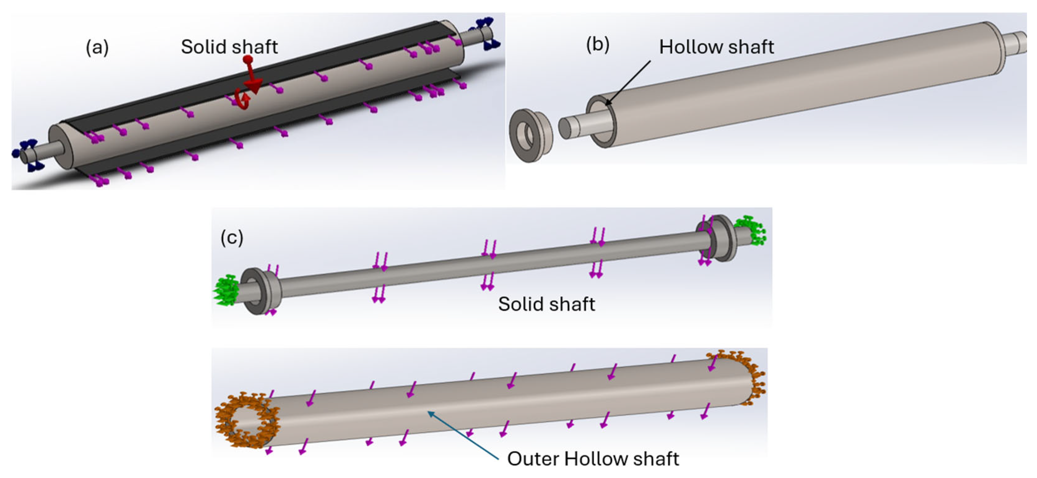
Figure 6a shows the initial design of the solid shaft used in the road cleaning machine and its design is to combine with the solid shaft and hollow shaft as seen fin
Figure 6b. The purple colors arrow in the image shows the force direction and red color arrow shows the torque.
In the shaft, most of the torsional stress is accumulated at the periphery and deflection is at its maximum at the center along the longitudinal direction. The hollow shaft is used to absorb torsional stress and bending stress absorbed by the solid shaft. Thus, the combination of solid and hollow shaft is used in the modified design.
Figure 6c shows the exploded view of the modified design of the shaft. The green color and brown color show the end load of the solid and hollow shaft respectively. The utilization of von Mises stress in the shaft is to estimate material yielding under intricate loading conditions based on the outcomes of uniaxial tensile tests. The von Mises stress in the shaft is characterized by the fact that there exists an equal amount of von Mises stress between two stress levels with equal distortion energy. According to the von Mises yield criterion, a material will yield if its von Mises stress under a load that is equal to or above its yield limit under simple torsion.
Figure 7a shows the yielding due to von Mises stress in N/m
2 for the initial design of the solid shaft, and it is compared with the von Mises stress in N/m
2 for the modified design of the solid shaft as well as that of the hollow shaft (
Figure 7c). The von Mises or comparable stress method is very suitable for the shaft made up of steel, while its applicability may be limited for certain castings or plastics. The maximum stress observed in
Figure 7 of a model may exhibit singularity rather than being actual. Defects can occasionally occur in a real-world shaft, which may influence the shaft’s von Mises stress and deflection.
Figure 6a shows the deflection in mm for the initial design of solid shaft and it is compared with the deflection in mm for the modified designs of the solid and hollow shafts (
Figure 8b,c). It is well known that the mechanical behavior of materials of the shaft is significantly influenced by its deformation, as it governs the material’s response to external loads due to debris. When a shaft is exposed to an external force, it undergoes deformation, resulting in a change in its shape, as seen in
Figure 8b,c. This phenomenon of deformation refers to the occurrence of warping, bending, twisting, and springiness in the structural elements of hollow and solid shaft-modified assemblies.
Figure 9 shows the variation in maximum stress and deformation at different diameters.
The rotation of the rakes propels the accumulated rubbish from the wedge configuration onto the conveyor belt. Subsequently, the waste is transported across the conveyor belt and deposited into the designated receptacle.
Figure 10a shows the four-blade rake used in the road cleaning vehicle.
Figure 10b shows the von Mises stress under operating conditions for the four bladed rake.
Figure 10c shows the deformation of the rake and in the finite element analysis (FEA); the calculation of von Mises stress is employed to forecast the deformation or failure of a certain structure. This prediction encompasses the assessment of various conditions within the rake structures.
The arrangement of the rake in the shaft is to create stress concentration in the joint. Thus, this von Mises yield criterion is employed in this scenario pertaining to intricate stress conditions and to perform structural examination, as well as to estimate the fatigue life. The term “equivalent plastic strain” is commonly used to refer to von Mises strain and its variations for different loads is shown in
Figure 11a and its deformation in
Figure 11b. While it consistently exhibits a positive sign, it does not always indicate a “tensile” strain. In contrast, the hydrostatic plastic strain consistently exhibits a value of zero [
17].
6. Conclusions
The design of the road cleaning vehicle was effectively executed, with a focus on optimizing crucial components. This project focused on the design and optimization of the components within the vehicle’s conveying system to ensure optimal performance and prevent any malfunctions.
The plot was generated by altering the shaft diameter of the roller to determine the diameter that would yield the lowest stress. The observed stress and deflection values were found to be within the permissible threshold. Furthermore, by the manipulation of shaft speed and load, it is estimated that the maximum stress and deformation is within the permitted threshold.
Through careful observation of the underlying reason for excessive deflection on the conveyor belt, a modification was made to the design by incorporating three idler rollers between the belt. This modification effectively reduced the deflection to a minimal level.
A model was constructed for the rake, including the bearings, and a static analysis was conducted to determine the maximum stress. Initially, this study was exclusively performed on the rake, and multiple stress and deformation plots were generated in relation to diameter, speed, and load in order to determine the optimal diameter. It was seen that the stress resulting from the specified parameters fell within acceptable thresholds. Subsequently, the bearing was isolated for investigation, and stress plots were obtained, revealing that it was within the permissible limit. Following this, the bearing was selected.
Author Contributions
Conceptualization, M.P.T.; methodology, M.P.T.; software, S.S.; validation, S.S.; formal analysis, M.P.T.; investigation, M.P.T.; resources, M.P.T. and S.S.; data curation, S.S.; writing—original draft preparation, M.P.T.; writing—review and editing, S.S. All authors have read and agreed to the published version of the manuscript.
Funding
This research received no external funding.
Institutional Review Board Statement
Not applicable.
Informed Consent Statement
Not applicable.
Data Availability Statement
No new data were created or analyzed in this study. Data sharing is not applicable to this article.
Conflicts of Interest
The authors declare no conflicts of interest.
References
- Beckman, J.A.; Crane, G.; Kay, E.L.; Laman, J.R. Scrap tire disposal. Rubber Chem. Technol. 1974, 47, 597–624. [Google Scholar] [CrossRef]
- Amato, F.; Querol, X.; Johansson, C.; Nagl, C.; Alastuey, A. A review on the effectiveness of street sweeping, washing and dust suppressants as urban PM control methods. Sci. Total Environ. 2010, 406, 3070–3084. [Google Scholar] [CrossRef] [PubMed]
- Ong, I.B.L.; Sovacool, B.K. A Comparative Study of Littering and Waste in Singapore and Japan. Resour. Conserv. Recycl. 2012, 61, 35–42. [Google Scholar] [CrossRef]
- Agrawal, P. Design of Garbage Truckfor Indian Cities. Master Thesis, University of Petroleum and Energy Studies, Dehraun, India, April 2015. [Google Scholar]
- Upakul, D. Trends in Beverage Packaging, 1st ed.; Grumezescu, A., Holban, A.M., Eds.; Elsevier: Amsterdam, The Netherlands, 2019; pp. 1–9. [Google Scholar]
- Helinski, O.K.; Poor, C.J.; Wolfand, J.M. Ridding Our Rivers of Plastic: A Framework for Plastic Pollution Capture Device Selection. Mar. Pollut. Bull. 2021, 165, 112095. [Google Scholar] [CrossRef] [PubMed]
- Buekens, A.; Zhou, X. Recycling Plastics from Automotive Shredder Residues: A Review. J. Mater. Cycles Waste Manag. 2014, 16, 398–414. [Google Scholar] [CrossRef]
- Kadam, H.A.; Hyalij, N.S. Design and Analysis of Belt Conveyor Roller Shaft. Int. J. Eng. Trends Technol. (IJETT) 2015, 36, 45–49. [Google Scholar] [CrossRef]
- Lamberti, L.; Venkataraman, S.; Haftka, R.T.; Johnson, T.F. Preliminary design optimization of stiffened panels using approximate analysis models. Int. J. Numer. Methods Eng. 2003, 57, 1351–1380. [Google Scholar] [CrossRef]
- Weickum, G.; Eldred, M.S.; Maute, K. A Multi-Point Reduced-Order Modeling Approach of Transient Structural Dynamics with Application to Robust Design Optimization. Struct. Multidiscip. Optim. 2009, 38, 599–611. [Google Scholar] [CrossRef]
- Katterfeld, A.; Roberts, A.; Wheeler, C.; Williams, K.; Wensrich, C.; Scholten, J.; Jones, M.; Kunze, G.; Strubelt, H.; Ilic, D.; et al. Conveying and Construction Machinery; Grote, K.H., Hefazi, H., Eds.; Springer: Cham, Switzerland, 2021; pp. 829–911. [Google Scholar]
- Vieira, J.M.M.; Campilho, R.D.S.G.; da Silva, F.J.G.; de Jesús Sánchez-Arce, I. Development of a rotation and lifting system for pallet rotary tables. Int. J. Adv. Manuf. Technol. 2022, 122, 4321–4339. [Google Scholar] [CrossRef]
- Feil, A.; Pretz, T. Mechanical recycling of packaging waste. In Plastic Waste and Recycling; Letcher, T.M., Ed.; Academic Press: Cambridge, MA, USA, 2020; pp. 283–319. [Google Scholar]
- Tayade, V.B.; Warade, S.A.; Shinde, M.R.; Bhanuse, V. Study, Design, Modification and Analysis of Charging Belt Conveyor System to Set Optimum Results. Int. J. Adv. Technol. Eng. Sci. 2015, 3, 194–202. [Google Scholar]
- Zhang, S.; Xia, X. Modeling and energy efficiency optimization of belt conveyors. Appl. Energy 2011, 88, 3061–3071. [Google Scholar] [CrossRef]
- He, D.; Pang, Y.; Lodewijks, G. Speed Control of Belt Conveyors during Transient Operation. Powder Technol. 2016, 301, 622–631. [Google Scholar] [CrossRef]
- Bajda, M.; Hardygóra, M. Analysis of the Influence of the Type of Belt on the Energy Consumption of Transport Processes in a Belt Conveyor. Energies 2021, 14, 6180. [Google Scholar] [CrossRef]
Figure 1.
Proposed design of the road wiping vehicle.
Figure 1.
Proposed design of the road wiping vehicle.
Figure 2.
Individual component drawing under analysis. (a) roller, (b) belt conveyer, (c) rack.
Figure 2.
Individual component drawing under analysis. (a) roller, (b) belt conveyer, (c) rack.
Figure 3.
(a) Initial design of belt conveyer with two rollers. (b) Modified design of the belt conveyer with additional support rollers.
Figure 3.
(a) Initial design of belt conveyer with two rollers. (b) Modified design of the belt conveyer with additional support rollers.
Figure 4.
(a) Von Mises stress in N/m2 for the initial design of belt conveyer with two rollers; (b) von Mises stress in N/m2 for the modified design of the belt conveyer with additional support rollers.
Figure 4.
(a) Von Mises stress in N/m2 for the initial design of belt conveyer with two rollers; (b) von Mises stress in N/m2 for the modified design of the belt conveyer with additional support rollers.
Figure 5.
(a) Static displacement in mm for the initial design of the belt conveyer with two rollers; (b) static displacement in mm for the modified design of the belt conveyer with additional support rollers.
Figure 5.
(a) Static displacement in mm for the initial design of the belt conveyer with two rollers; (b) static displacement in mm for the modified design of the belt conveyer with additional support rollers.
Figure 6.
(a) Initial design of the solid shaft used in the road cleaning machine. (b) Modified design of the shaft in combination with the solid shaft and hollow shaft. (c) Exploded view of the modified design of the shaft. The direction of the arrow in the image shows the force direction in the constraint.
Figure 7.
(a) Von Mises stress in N/m2 for the initial design of the solid shaft. (b) Von Mises stress in N/m2 for the modified design of the solid shaft. (c) Von Mises stress in N/m2 for the modified design of the hollow shaft.
Figure 7.
(a) Von Mises stress in N/m2 for the initial design of the solid shaft. (b) Von Mises stress in N/m2 for the modified design of the solid shaft. (c) Von Mises stress in N/m2 for the modified design of the hollow shaft.
Figure 8.
(a) Deflection in mm for the initial design of the solid shaft. (b) Deflection in mm for the modified design of the solid shaft. (c) Deflection in mm for the modified design of the hollow shaft.
Figure 8.
(a) Deflection in mm for the initial design of the solid shaft. (b) Deflection in mm for the modified design of the solid shaft. (c) Deflection in mm for the modified design of the hollow shaft.
Figure 9.
Relation between shaft diameter, stress, and deformation.
Figure 9.
Relation between shaft diameter, stress, and deformation.
Figure 10.
(a) Four-blade rakes used in a road cleaning vehicle. (b) Von Mises stress in N/m2 for the four-blade rake. (c) Deflection in mm for the four-blade rake.
Figure 10.
(a) Four-blade rakes used in a road cleaning vehicle. (b) Von Mises stress in N/m2 for the four-blade rake. (c) Deflection in mm for the four-blade rake.
Figure 11.
(a) Variations in von Mises stress for different loads. (b) Variations in deflection for different loads in the rake.
Figure 11.
(a) Variations in von Mises stress for different loads. (b) Variations in deflection for different loads in the rake.
Table 1.
Materials of the major components.
Table 1.
Materials of the major components.
| Components | Roller | Housing | Pulley | Rake | Belt |
|---|
| Materials | Plain Carbon Steel | Stainless Steel | Stainless Steel | Plain Carbon Steel | Rubber |
| Modulus of Elasticity | 2.1 × 10¹¹ N/m2 | 2 × 10¹¹ N/m2 | 2 × 10¹¹ N/m2 | 2.1 × 10¹¹ N/m2 | 0.06 × 10⁸ N/m2 |
| Poisson’s Ratio | 0.28 | 0.28 | 0.28 | 0.28 | 0.49 |
| Yield Strength | 2.2 × 10⁸ N/m2 | 1.72 × 10⁸ N/m2 | 1.72 × 10⁸ N/m2 | 2.2 × 10⁸ N/m2 | 0.092 × 10⁸ N/m2 |
Table 2.
Comparison of the analytical and numerical results for the roller.
Table 2.
Comparison of the analytical and numerical results for the roller.
| Description | Analytical | Numerical |
|---|
| Maximum bending stress (MPa) | 2.0375 | 2.031 |
| Maximum deflection (mm) | 0.00867 | 0.0079 |
Table 3.
Comparison of the analytical and numerical results for the belt conveyer.
Table 3.
Comparison of the analytical and numerical results for the belt conveyer.
| Description | Analytical | Numerical |
|---|
| Maximum bending stress (MPa) | 0.122 | 0.2438 |
| Maximum deflection (mm) | 0.000226 | 0.000283 |
Table 4.
Comparative table of the results before and after incorporating idler rollers.
Table 4.
Comparative table of the results before and after incorporating idler rollers.
| Total Load on Conveyor (N) | Stress (Max) (N/m2) | Deformation (Max) (mm) |
|---|
| Before Incorporating Idler Rollers | After Incorporating Idler Rollers | Before Incorporating Idler Rollers | After Incorporating Idler Rollers |
|---|
| 10 | 529,238.29 | 27,169.96 | 249 | 1.062 |
| 20 | 705,820.65 | 40,097.72 | 299 | 1.445 |
| 30 | 876,366.32 | 50,909.98 | 349 | 1.872 |
| 40 | 935,155.61 | 60,393.10 | 399 | 2.266 |
| Disclaimer/Publisher’s Note: The statements, opinions and data contained in all publications are solely those of the individual author(s) and contributor(s) and not of MDPI and/or the editor(s). MDPI and/or the editor(s) disclaim responsibility for any injury to people or property resulting from any ideas, methods, instructions or products referred to in the content. |
© 2025 by the authors. Licensee MDPI, Basel, Switzerland. This article is an open access article distributed under the terms and conditions of the Creative Commons Attribution (CC BY) license (https://creativecommons.org/licenses/by/4.0/).


