1. Introduction
In the manufacturing process of precision micro parts, burrs generated during the cutting and grinding processes cause various problems. The deburring of the inner surface of elongated pipes relies on manual work. Conventional deburring tools are applied to the outer surface of parts, but challenges exist in using them for the inner surface of parts or in pipes. Thus, the development of new internal surface deburring methods is necessary.
In the manufacturing process for hypodermic needles for human use, traditional technologies such as electrolytic polishing and shot blasting are used to remove burrs generated during the cutting and grinding processes. However, while shot blasting can deburr the needle’s tip, the process also generates a new, inward-facing secondary burr on the chin part of the needle. This secondary burr causes various problems so there is a high demand for the development of new precision deburring technologies.
The magnetic abrasive finishing process is a new process that removes materials. This process is used for the precision finishing of tube interiors, the mirror finishing of planar workpieces, and the precision edge finishing of the workpiece with complex curved shapes. The plane magnetic abrasive finishing process [
1,
2,
3,
4,
5,
6,
7,
8,
9,
10,
11,
12] creates a flexible magnetic brush between the magnetic pole and the workpiece to realize a precision finish on the workpiece surface.
Therefore, we developed a high-efficiency, high-precision magnetic deburring method for the inner surfaces of pipes and flat surfaces [
13,
14,
15]. This newly developed magnetic deburring method adopted a high-frequency vibration magnetic brush to remove the inward-facing secondary burr generated on the chin part of hypodermic needles by shot blasting. This method enables the production of high-quality hypodermic needles.
2. Processing Principle
Figure 1 shows a schematic diagram of the processing principle. A magnetic pole unit consists of N and S magnets arranged in opposite directions (180°). These magnets are connected by a magnetic yoke made of ferromagnetic material to enhance the magnetic field between the poles. When mixed magnetic particles are supplied between the magnetic poles, they become magnetized in the magnetic field and form a particle brush along the magnetic lines of force. Since the magnetic particle brush behaves flexibly, when a hypodermic needle (Kaneko MediX, Inc., Tochigi, Japan) is inserted into the brush, the particle brush is separated along the inner and outer surfaces of the needle. The individual magnetic particles, magnetized by the magnetic field, exert a magnetic force that presses against the workpiece. When a high-frequency, unidirectional vibrational motion is applied to the workpiece, relative motion occurs between the workpiece and the magnetic abrasive particles due to the vibration and magnetic holding force, enabling precise deburring.
Figure 2 shows the force analysis of the magnetic particles in the magnetic field. A magnetic particle along the magnetic equipotential line direction generates a force
while a force
is generated along the magnetic force line direction using, expressable as the following (1) [
1,
2,
3]:
where
is the volume of magnetic particles,
is the susceptibility of abrasive particles,
is the permeability of the vacuum,
is the magnetic field intensity, and
and
are gradients of magnetic field intensity in
and
directions, respectively.
The magnetic force acts on each particle of the mixed magnetic abrasive, and the strength of this force depends on the volume of the magnetic abrasive grains and the distance between the magnetic poles.
3. Experimental Setup and Method
3.1. Experimental Setup
Figure 3 shows an external view of the experimental setup and an enlarged photo of the processing area. N and S magnets (Nd-Fe-B, 18 × 12 × 10 mm) were attached to a yoke (made of SS400 steel) with opposing poles on the top and bottom, and magnetic poles (SS400) were attached to the ends. By connecting the small vibrator to a power amplifier, the vibration frequency is freely changed between 0 and 100 Hz. The small vibrator used was the EMIC 511-A. As shown in the figure, the magnetic field was strengthened by connecting the magnetic poles to a magnetic yoke to form a closed magnetic circuit. The gap between the magnetic poles was freely adjusted to adjust the gap between the magnetic poles.
3.2. Method
The workpiece used in this experiment was a human hypodermic needle (SUS304) with an outer diameter of 2.4 mm, an inner diameter of 2.15 mm, and a total length of 72 mm. Deburring experiments were performed under certain conditions. After the deburring experiment, the workpiece was cleaned with an ultrasonic cleaner. After cleaning, the jaws of the needle were cut using a wire electric discharge machine so that the inner surface was observed. The workpiece was observed and evaluated using a scanning electron microscope (SEM).
4. Magnetic Conditions and Results
In this study, experiments were conducted under various experimental conditions to examine the feasibility and processing characteristics effects of the magnetic deburring method proposed in this study.
4.1. Effect of Type and Size of Mixed Magnetic Particles
4.1.1. Conditions and Method
The mixed magnetic abrasive particles were placed between the magnetic poles to form a magnetic brush. The workpiece, a hypodermic needle with an outer diameter of 2.4 mm, an inner diameter of 2.15 mm, and a length of 72 mm (SUS304), was fixed to a vibrator when vibrating. The experimental conditions are shown in
Table 1. The magnetic pole spacing was set to 4 mm, the vibration frequency to 70 Hz, and the vibration amplitude to 1.5 mm. After machining, the workpiece was cleaned in an ultrasonic cleaner and cut using a wire electric discharge machine so that the inner surface of the jaw of the needle could be observed using a scanning electron microscope.
4.1.2. Results and Discussion
In the experiment using Type 1 mixed magnetic abrasive, clear scratches were observed on the outer surface of the injection needle after 10 min of testing. Therefore, the Type 1 experiment was stopped after 10 min.
Figure 4 shows the experimental results for Type 2 and Type 3 with mixed magnetic abrasive grains for a machining time of 30 min. When mixed magnetic abrasive Types 2 and 3 were used, almost no scratches were observed on the outer surface of the needle after 10 min of processing, but the burr removal was insufficient. The results of the 30-min deburring experiment revealed that the burr was completely removed. However, observation revealed scratches on the outer surface of the needle. The results showed that the outer surface of the injection needle was damaged when large-sized magnetic particles were used as they generated a strong magnetic force to remove burrs from injection needles. Therefore, it is necessary to select the size of the magnetic particles appropriately.
4.2. Machining Characteristics with KMX Magnetic Abrasive Grains
An experiment was conducted using only magnetic abrasive KMX (80 µm) to examine the effect on machining characteristics.
In the experiment, 2.0 g of KMX (80 µm) mixed with 0.12 mL of water-soluble abrasive liquid was used as a magnetic brush and machining was performed for 10 min. Other experimental conditions were the same as in the previous experiment. The experimental results are shown in
Figure 5.
Burrs on the jaw of the injection needle were removed as shown in
Figure 5. In addition, there were no irregularities when machining was performed for 10 min with mixed magnetic abrasive type 1, and there were no scratches on the outer surface of the injection needle.
4.3. Effect of Vibration Frequency
4.3.1. Conditions and Method
Table 2 shows the experimental conditions. A deburring experiment was carried out on a SUS304 stainless steel human hypodermic needle with an inner diameter of 2.4 mm and an outer diameter of 2.15 mm, using mixed magnetic abrasive particles consisting of electrolytic iron powder (149 μm), KMX (80 μm), and 0.12 mL of water-soluble abrasive liquid. The workpiece vibration frequency was set to 90 and 100 Hz, and the jaw of the hypodermic needle was observed using SEM after processing. The hypodermic needle before processing was observed and measured in the same way. The processing time was set to 45 and 60 s, and processing experiments were carried out for each.
4.3.2. Results and Discussion
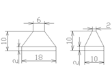
In the experiment, the jaw part was observed from the front with the hypodermic needle lying down (SEM image (I)), and the inside of the jaw part was observed with the needle standing with the tip facing straight up (SEM image (II)). The SEM image before processing is shown in
Figure 6. There were burrs on the jaw part of the tip of the injection needle.
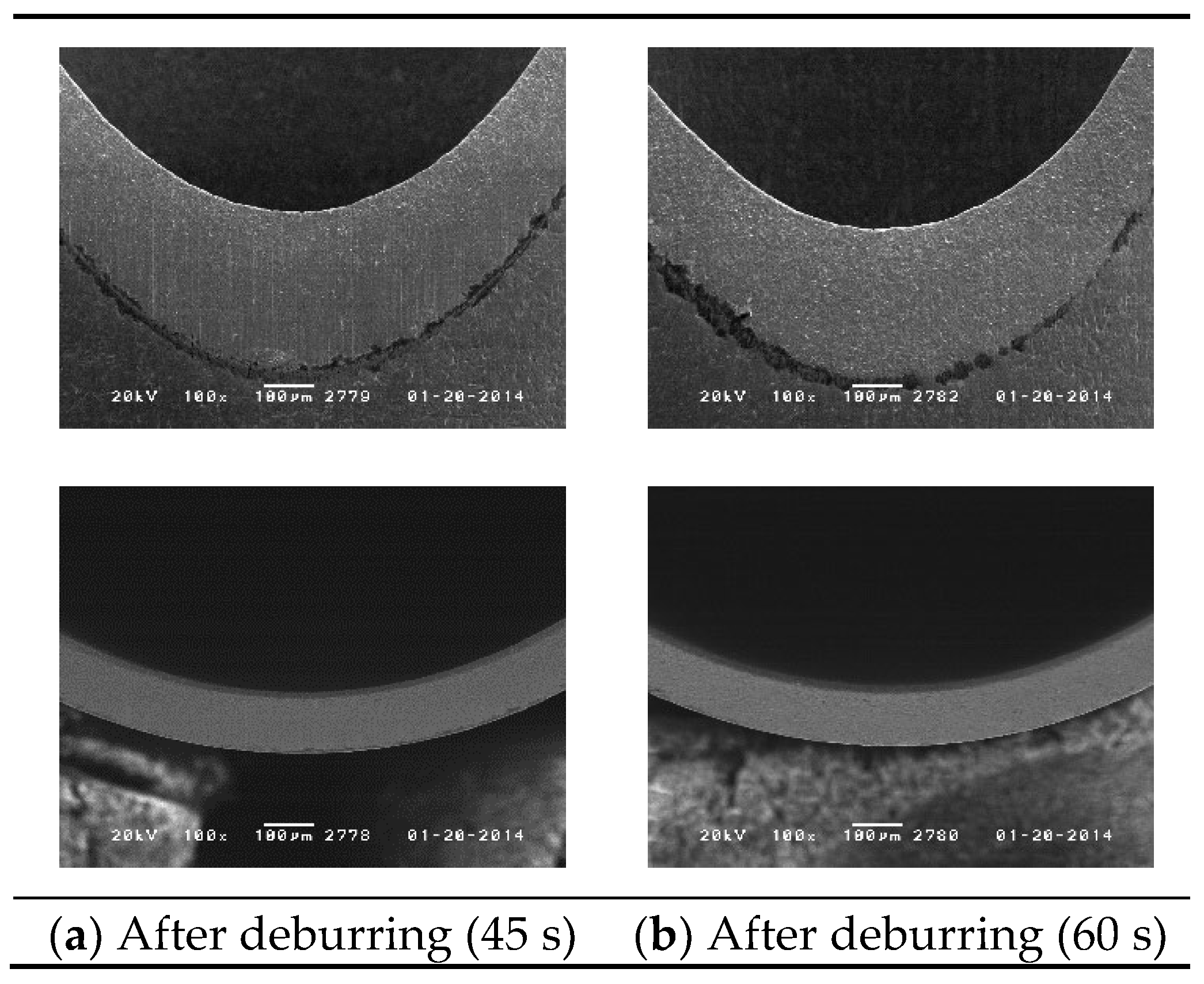
Figure 7 shows an SEM image after machining. Burrs were sufficiently removed in machining times of 45 and 60 s when the workpiece vibration frequency was 90 Hz. Regarding the machining marks on the jaw cross-section, it was confirmed that they remained after 45-s machining, but were completely removed after 60-s machining.
Figure 8 shows an SEM image after machining. When machining with a workpiece vibration frequency of 100 Hz, burrs were sufficiently removed by machining for both 45 and 60 s, just as in the case of 90 Hz. In particular, with machining for 45 s; although fine irregularities remained on the inside of the jaw, the machining marks on the cross-section of the jaw were completely removed. Machining for 60 s removed burrs on the outside and inside of the jaw and removed machining marks on the cross-section.
Funding
This research was supported by the MEXT Grant-in-Aid for Scientific Research, Grant Number: JP 24K07248.
Institutional Review Board Statement
Not applicable.
Informed Consent Statement
Not applicable.
Data Availability Statement
No new data were created or analyzed in this study. Data sharing is not applicable to this article.
Acknowledgments
I would like to express my sincere gratitude to Kaneko MediX, Inc. for providing the samples used in this study. I am also grateful to the students in this laboratory who were involved in or contributed to this research project.
Conflicts of Interest
The authors declares no conflict of interest.
References
- Shinmura, T.; Takazawa, K.; Hatano, E.; Aizawa, T. Study on magnetic abrasive process (finishing characteristics). Bull. Jpn. Soc. Precis. Eng. 1984, 18, 347–348. [Google Scholar]
- Shinmura, T.; Takazawa, K.; Hatano, E.; Matsunaga, M.; Matsuo, T. Study on magnetic abrasive finishing. CIRP Ann. 1990, 39, 325–328. [Google Scholar] [CrossRef]
- Natsume, M.; Shinmura, T. Study on the mechanism of plane magnetic abrasive finishing process-Elucidation of normal force characteristics. Jpn. Soc. Mech. Eng. 2008, 74, 212–218. (In Japanese) [Google Scholar]
- Jain, V.K. Magnetic field assisted abrasive based micro-/nano-finishing. J. Mater. Process. Technol. 2009, 209, 6022–6038. [Google Scholar] [CrossRef]
- Bagehorn, S.; Wehr, J.; Maier, H.J. Application of mechanical surface finishing processes for roughness reduction and fatigue improvement of additively manufactured Ti-6Al-4V parts. Int. J. Fatigue 2017, 102, 135–142. [Google Scholar] [CrossRef]
- Shinmura, T.; Aizawa, T. Study on magnetic abrasive finishing process development of plane finishing apparatus using a stationary type electromagnet. Bull. Jpn. Soc. Precis. Eng. 1989, 23, 236–239. (In Japanese) [Google Scholar]
- Shinmura, T.; Takazawa, K.; Hatano, E.; Aizawa, T. Study on magnetic abrasive finishing (2nd report) finishing characteristics. J. Jpn. Soc. Precis. Eng. 1986, 52, 1761–1767. (In Japanese) [Google Scholar] [CrossRef]
- Shinmura, T.; Aizawa, T. Development of plane magnetic abrasive finishing apparatus and its finishing performance (2nd report) finishing apparatus using a stationary type electromagnet. J. Jpn. Soc. Precis. Eng. 1988, 54, 928–933. (In Japanese) [Google Scholar] [CrossRef]
- Shinmura, T.; Yamaguchi, H. Study on a new internal finishing process by the application of magnetic abrasive machining: Internal finishing of stainless steel tube and clean gas bomb. JSME Int. J. Ser. C 1995, 38, 798–804. (In Japanese) [Google Scholar] [CrossRef]
- Yamaguchi, H.; Shinmura, T.; Kobayashi, A. Development of an internal magnetic abrasive finishing process for nonferromagnetic complex shaped tubes. JSME Int. J. Ser. C 2001, 44, 275–281. [Google Scholar] [CrossRef]
- Yin, S.H.; Shinmura, T. A comparative study: Polishing characteristics and its mechanisms of three vibration modes in vibration-assisted magnetic abrasive polishing. Int. J. Mach. Tool. Manuf. 2012, 44, 383–390. [Google Scholar] [CrossRef]
- Yin, S.H.; Shinmura, T. Vertical vibration-assisted magnetic abrasive finishing and deburring for magnesium alloy. Int. J. Mach. Tools Manuf. 2004, 44, 1297–1303. [Google Scholar] [CrossRef]
- Xie, H.J.; Zou, Y.H.; Dong, C.W.; Wu, J.Z. Study on the magnetic abrasive finishing process using alternating magnetic field: Investigation of mechanism and applied to aluminum alloy plate. Int. J. Mach. Tools Manuf. 2019, 102, 1509–1520. [Google Scholar] [CrossRef]
- Xu, J.Y.; Zou, Y.H. Development of a new magnetic abrasive finishing process with renewable abrasive particles using the circulatory system. Precis. Eng. 2021, 72, 417–425. [Google Scholar] [CrossRef]
- Zou, Y.H.; Shinmura, T. A study on the magnetic field assisted machining process for internal finishing using a magnetic machining jig. Key Eng. Mater. 2004, 257–258, 505–510. [Google Scholar] [CrossRef]
| Disclaimer/Publisher’s Note: The statements, opinions and data contained in all publications are solely those of the individual author(s) and contributor(s) and not of MDPI and/or the editor(s). MDPI and/or the editor(s) disclaim responsibility for any injury to people or property resulting from any ideas, methods, instructions or products referred to in the content. |
© 2025 by the author. Licensee MDPI, Basel, Switzerland. This article is an open access article distributed under the terms and conditions of the Creative Commons Attribution (CC BY) license (https://creativecommons.org/licenses/by/4.0/).


