Proceeding Paper

The Integration of Solar Panels onto a Carbon Fiber Structure for a Solar-Powered UAS †

1
Department of Mechanical and Aerospace Engineering (DIMEAS), Politecnico di Torino, 10129 Turin, TO, Italy
2
Solbian Energie Alternative Srl, 10051 Avigliana, TO, Italy
*
Author to whom correspondence should be addressed.
Presented at the 14th EASN International Conference on “Innovation in Aviation & Space towards sustainability today & tomorrow”, Thessaloniki, Greece, 8–11 October 2024.
Eng. Proc. 2025, 90(1), 57; https://doi.org/10.3390/engproc2025090057
Published: 17 March 2025

Abstract

:
For a solar-powered unmanned aerial system (UAS), the performance and integration of the solar panel are of paramount importance. This paper examines the safety aspects of solar panels in electrical power systems, with a particular focus on the installation of solar cells onto an aircraft’s carbon fiber wing. Three distinct installation techniques are evaluated, and their respective advantages and disadvantages are discussed. A preliminary test is conducted to assess the viability of adhering commercial solar panels intended for boats using a bio-adhesive layer placed underneath the series of encapsulated solar panels. To ensure adhesion, the piece is placed under a vacuum. The subsequent test evaluates the lamination of the solar cells onto the carbon fiber skin with a resin as a component of the laminate. Finally, as a definitive solution, the adhesion of the solar panels onto the entire polymer layer used to seal the solar cells themselves was evaluated. This solution offers objective advantages in terms of adhesion, lightness and whiteness. Adhesion is guaranteed by the bond of the thermoplastic polymer used to seal the photovoltaic cells and the epoxy resin of the laminate. The bond is created through the autoclave process, which involves placing the laminate and solar cells in an oven at a specific temperature and pressure for a defined period of time. This solution results in a weight reduction of approximately three times compared to a solution not specifically designed for these materials and a reduction in thickness of approximately two times.

1. Introduction

Clean aviation has become one of the most technologically significant challenges in aeronautical engineering in recent decades [1]. In fact, increasingly stringent global requirements for decarbonization and reductions in greenhouse gas emissions also compel the aviation industry to update its production methods and rethink the design of key onboard systems [2]. One of the main areas of application involves the development of electrically powered aircraft, particularly through the use of onboard photovoltaic systems [3]. Despite this solution not currently being feasible for civil aviation aircraft, it has been the object of extensive research for several years when it comes to unmanned aerial vehicles (UAVs), such as the renowned Solar Impulse 2 project [4,5]. The development of these systems could lead to the creation of fleets of aircraft with minimal or zero environmental impact, capable of supporting various mission profiles. At the Politecnico di Torino University (Italy), an ambitious research project is underway to develop a fully electric propulsion UAV using solely solar power [6]. This project, named RA-Record Aircraft, aims to achieve the challenging goal of developing a prototype capable of sustainable and carbon-neutral flight with unlimited autonomy. The project is managed by the Icarus PoliTo Team, a student team born inside the Politecnico di Torino university. Since its founding, the team has had a strong focus on innovation in aerospace, in particular by designing and developing both unmanned aerial vehicles (UAVs) and model rockets employed in renowned international student competitions (Air Cargo Challegne, Euroc, etc.). Launched in 2017, RA-Record Aircraft aligns with global energy and environmental challenges by relying on solar energy to power its electric motor and onboard systems. By integrating high-efficiency solar panels and energy storage solutions, RA 2.0 contributes to pursuing steps towards greener aviation technologies. The project’s first prototype, Amelia FP (First Prototype), marked a pivotal milestone. Designed with a lightweight carbon fiber structure, it aimed to optimize flight efficiency and energy capture. Amelia successfully completed its initial flight tests in 2022, enabling further enhancements. Nowadays, the team is developing the second prototype, born to deepen the challenges started with Amelia. The aircraft will have a length of 2.70 m from the tip to the bottom, a wingspan of 7.3 m and a tail width of 3 m. It is meant to have a 10 h flying autonomy at a cruise speed of 12 m/s, supported by a global battery capacity of 4.8 Ah. The battery must be powered by an array of 210 solar cells, divided between the wings (166 cells) and the tail (44 cells), forming an occupied surface area of around 3.79 m2. The recent developments of the project suggest that the final construction of the aircraft will be finished in spring 2025 and the final design is represented by the prototype render shown in Figure 1. To develop the flying prototype, one of the most critical aspects is the methodology for integrating photovoltaic cells onto the wing surface. This process is highly challenging as it affects both the aerodynamics of the wing and the determination of the power required to supply the propulsion system and, more broadly, the onboard systems. The combination of these factors necessitates meeting a particularly stringent requirement: achieving minimal invasiveness (to avoid altering the aerodynamic profile of the wing) while ensuring highly efficient adhesion (to prevent the degradation of solar cell performance). This paper aims, therefore, to find an efficient solution to this crucial question. In the following sections, several methodologies of solar cell array integration onto the wings are designed, developed and compared in order to define the best compromise.

2. Materials and Methods

As described in the introduction, a key aspect in the development of the second prototype for the project is defining the best strategy for integrating photovoltaic cells onto the wing structure. In this article, three different solutions were developed, tested and compared:
  • The simple adhesion of premanufactured solar cell arrays onto the upper wing surface;
  • The lamination of solar cells during the manufacturing process of the external wing skin;
  • Adhesion using a polymer film.

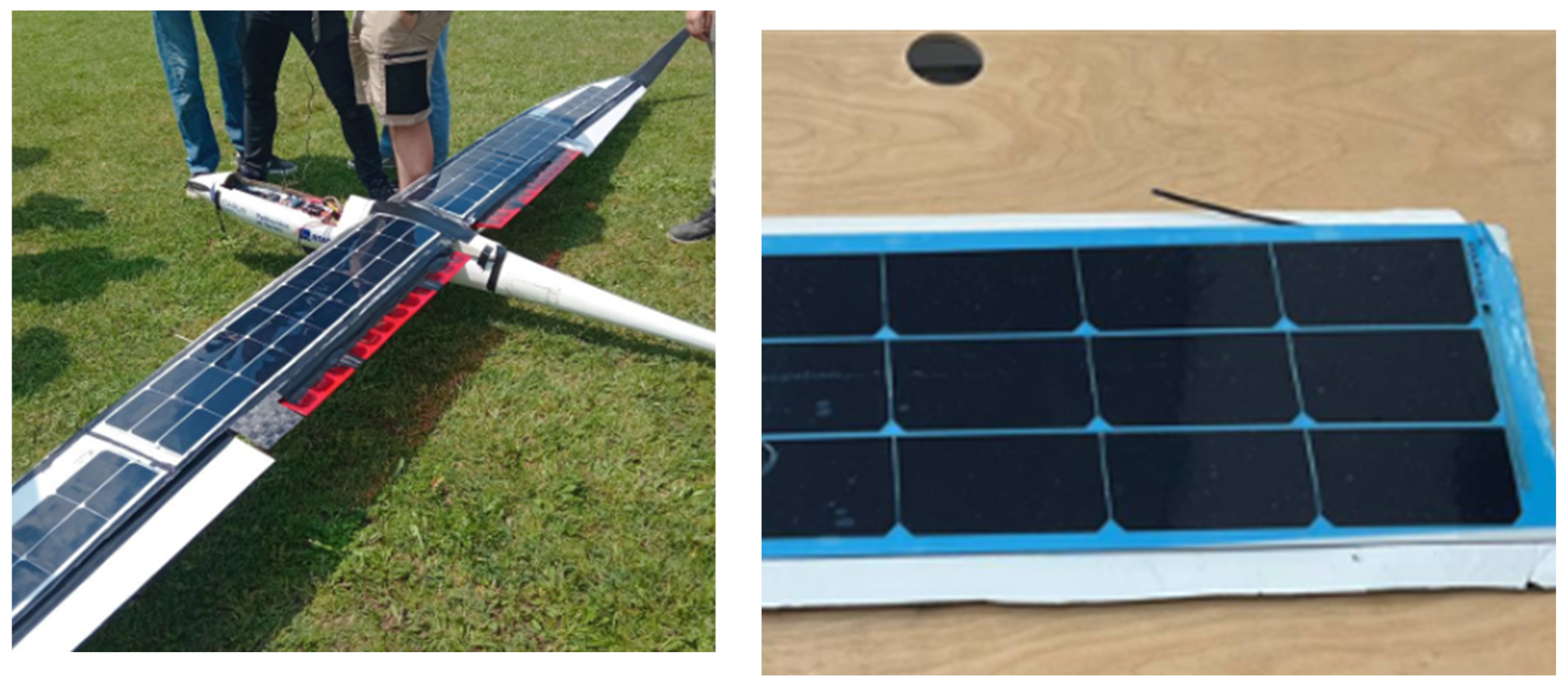
2.1. Simple Gluing of Pre-Manufactured Arrays of Solar Cells

The first strategy considered was the same approach adopted for the solar cell array integration onto the first prototype, Amelia. Indeed, its design phase was developed without considering the possibility of building a solar-powered aircraft. Only in a second iteration was it decided to upgrade the prototype by enabling it to perform a flight using solar energy. Therefore, a simple integration method was performed; specifically, by adhering a prefabricated solar cell array to the carbon fiber wing using adhesive. The following steps were undertaken to complete the integration:
  • The accurate cleaning of the surface to ensure the most effective possible adhesion;
  • The insertion of bubble wrap inside the wing structure to prevent excessive loads on the structure during the application of vacuum pressure;
  • The adhesion of the solar cell array onto the wing;
  • Wing placement in a vacuum bag and application of vacuum pressure to ensure optimal adhesion.
The final result of this process is shown in Figure 2, with the solar cells integrated onto the Amelia prototype. Thanks to this aircraft, it was possible to carry out the first flight tests with Amelia solely using solar-powered electric propulsion. These preliminary flights allowed the team to highlight with great clarity the strengths as well as the main limitations of the approach adopted.
The approach of directly gluing solar cells onto an existing structure guarantees not negligible advantages. Firstly, it is highly flexible, as it allows their integration without requiring prior consideration during the design phase. This approach significantly reduces both the costs and time required for adaptation, enabling the addition of new functionalities to pre-existing systems. Then, a second great benefit is represented by the system’s overall reversibility. The bonded solar cell array can theoretically be removed and replaced in case of damage or to accommodate updates; this feature not only improves the solution’s durability and sustainability but also ensures its adaptability to technological advancements or evolving system requirements. A final great advantage of this solution is represented by the cell’s integrity; by avoiding the direct involvement of their surface during the integration process, the induced losses in terms of energy production were quite negligible.
However, important critical aspects were also detected. The challenges encountered were primarily related to issues of mass and aerodynamics. In terms of mass, the choice to exclude solar-powered flight considerations during the initial design phase—and the subsequent decision to integrate solar cells later through simple adhesive bonding—led to a substantial increase in weight. This was mainly caused by the materials used for encapsulating the solar cell array and ensuring proper adhesion. Additionally, applying adhesive bonding directly onto an existing surface resulted in an undesired increase in thickness, which significantly affected the aerodynamics and, as a consequence, the performance of the prototype. This issue could have been mitigated during the design phase by incorporating a recessed area to house the encapsulated solar cell array, thereby preserving the original wing profile.

2.2. Lamination of Solar Cells

In this method, the solar cells were integrated directly during the lamination of the carbon fiber that forms the wing’s structure and the external skin. The lamination process involves layering oriented sheets of carbon fibers, which are impregnated with epoxy resin and hardener, one on top of the other. These layers are then left to cure—sometimes using an autoclave, if pre-impregnated carbon is used—with the help of a vacuum bag to create a rigid composite. Once the desired number of carbon fiber layers is achieved, the solar cells are placed on top of the final layer (or beneath the first layer if a negative mold is used), becoming the outermost layer of the structure. Moreover, different materials and related procedures have been used to protect the surface and the structure of the solar cells, chosen to be compatible with the lamination process itself:
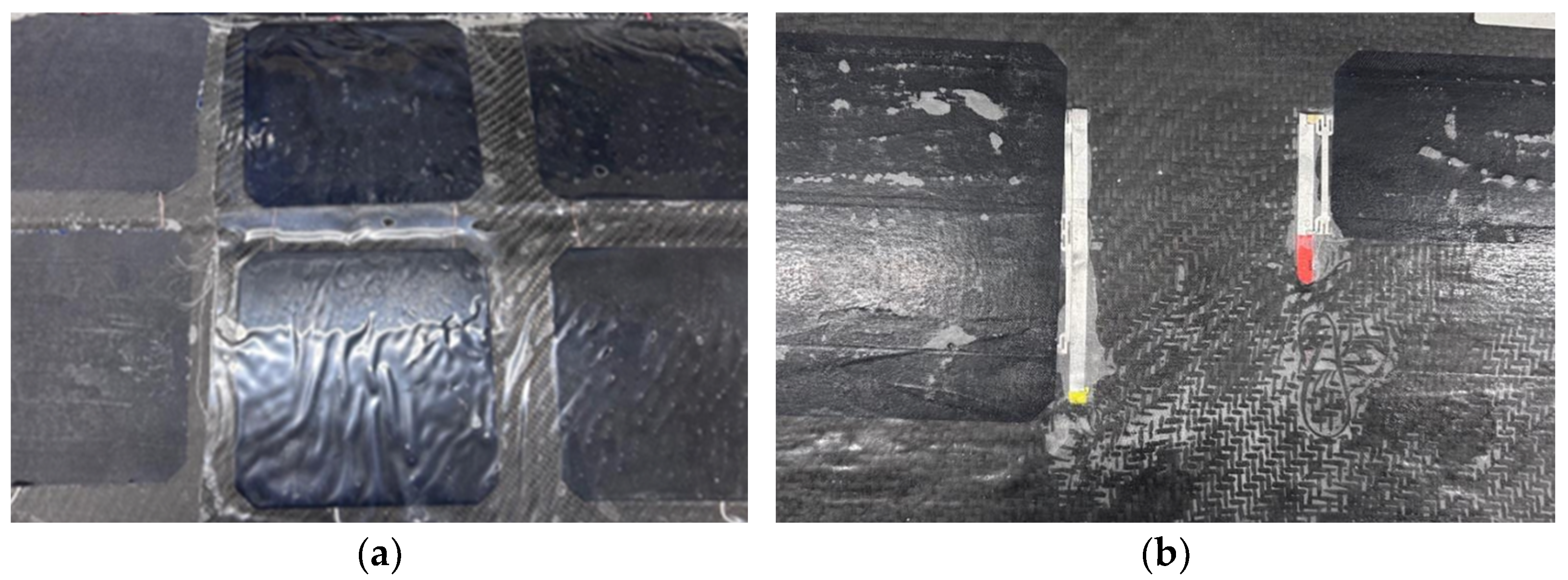
  • Gelcoat (Figure 3a) is a transparent gel generally used for the external finishing of composite material products. The results showed a lower final opacity than those obtained with only epoxy resin, but an irregular uniformity on the surface, in addition to a considerable weight;
  • Peel ply (Figure 3a) is a semi-transparent fabric generally made of nylon soaked in epoxy resin and hardener. When it was used to cover the cells, the tests showed a very high opacity, a fairly uniform surface finish and a fairly low weight.
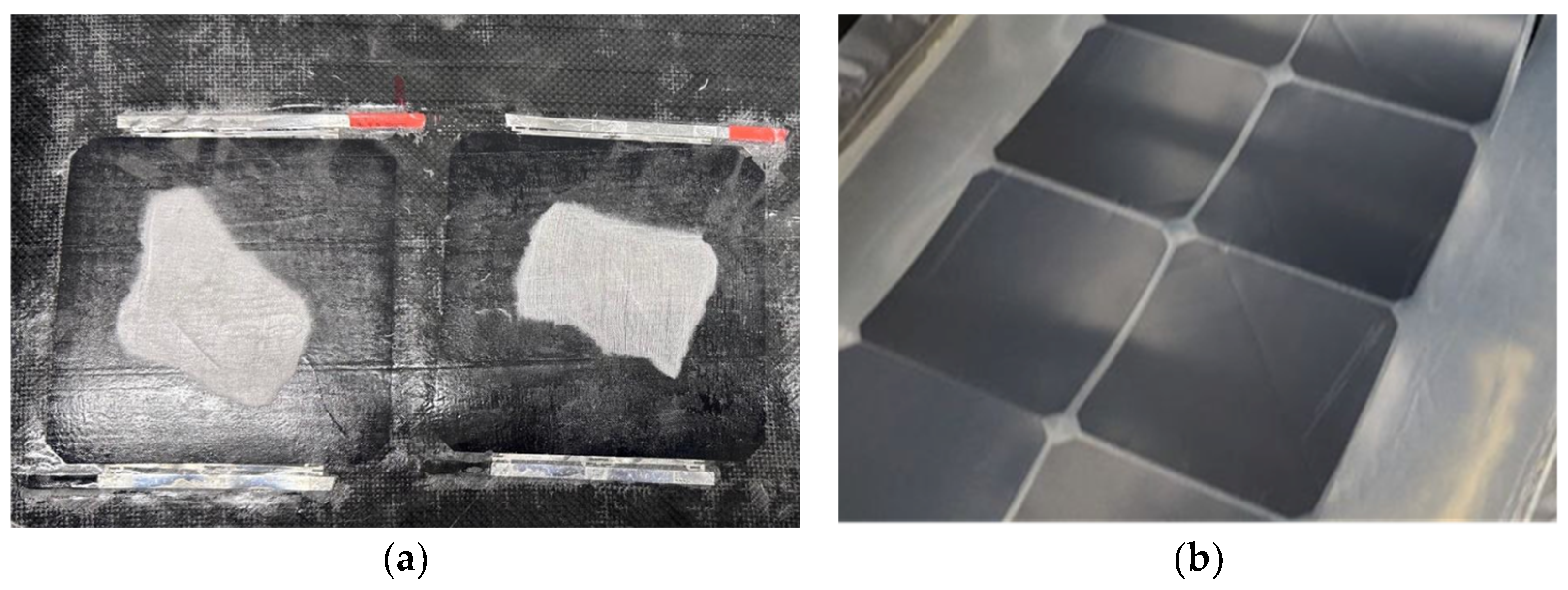
  • Glass fiber was used to cover the solar cells, either completely soaked in resin (Figure 3b) or placed only on top of the cells (Figure 4a) while the resin used to impregnate the carbon fiber was still wet. In both cases, the opacity was high, as the resin spread over most of the cells due to capillary action. Additionally, this resulted in a very rough surface finish.

2.3. Integration of Solar Cells with Polymeric Films

The final method was developed in collaboration with Solbian Energie Alternative Srl, focusing on integrating solar cells with polymeric films during a process of lamination. The primary objective was to minimize weight and thickness while ensuring adequate resistance to bending stresses. These stresses are particularly critical during turbulent flight conditions or demanding mission phases, such as landing. The first step in this method, the lamination process, plays a vital role in ensuring durability and weather resistance. This process securely encapsulates the solar cells between protective layers, enhancing the robustness of the solar panel. It involves multiple stages, from material preparation to cooling. Once the solar cells are electrically connected, they are sandwiched between two sheets of thermoplastic polyolefin (TPO) and covered with a single thin weather-resistant film made of polyvinyl fluoride (PVF). The lamination is carried out in a specialized machine called a laminator, which consists of two chambers separated by a flexible silicone membrane. Heating plates are located at the bottom of the laminator. The process involves three main phases:
  • Evacuation Phase: The material stack is placed in the lower chamber of the laminator, then air is pumped out from both the upper and lower chambers, therefore no pressure is applied to the stack during this phase.
  • Pressure and Heating Phase: The upper chamber valve is released, allowing a controlled amount of air to enter. This incoming air applies the desired pressure onto the stack, increasing the heat conduction from the heated plates. The temperature rises quickly and stabilizes between 130 °C and 150 °C, according to the specifications of the encapsulation material used.
  • Cooling Phase: After the encapsulant is fully processed, the panel is removed from the chambers and the panel is cooled down to approximately 80 °C by means of force convection.
The result of the lamination process is an array of solar cells encapsulated between polymer films, as shown in Figure 4b. Excess material is trimmed to leave a border of approximately 1.5 cm around the cells. The resulting panel can then be mounted on various surfaces using different techniques. In this work, the focus was on placement onto carbon fiber panels, which were selected as the structural material for the UAV. To mount the encapsulated solar cells onto carbon fiber panels, two primary methods were tested: EVA Layer Integration and Direct Placement. In the first case, a layer of EVA (ethyl vinyl acetate) was placed between the carbon fiber panel and the encapsulated cells. The weight and thickness of the assembly for this method are shown in Table 1. In direct placement, the encapsulated cells were placed directly onto the carbon fiber panel without any intermediary layer. The weight and thickness for this method are shown in Table 2. This method was also tested with thinner polymer films, with the corresponding weight and thickness displayed in Table 3. For both methods, a layer of peel ply (a release fabric) was placed over the solar cells. In the tests corresponding to Table 1 and Table 2, an additional layer of Breather fabric (an absorbent material) was also used. However, in subsequent tests, the Breather fabric was excluded, as its irregular texture caused the surface of the cells to adopt an undesirable uneven shape. The entire assembly was placed inside a vacuum bag and then transferred to a climate chamber. Once the chamber temperature reached 120 °C, the setup was maintained at this temperature for 20 min. Throughout this phase, a vacuum pump ensured that the vacuum inside the bag was maintained. As the polymer films melted during the heating process, they adhered directly to the carbon fiber panel, eliminating the need for adhesives or additional bonding agents. This approach saved weight, as using glue would have added approximately 90 g/m2. After 20 min at the desired temperature, the assembly was removed from the climate chamber, allowed to cool and then taken out of the vacuum bag. The peel ply (and, if used, the Breather) was easily removed without resistance, leaving the solar cells securely bonded to the carbon fiber panel.

3. Results and Discussion

Comparing the results of the three proposed methodologies, it became evident that the first two approaches (simple bonding and direct lamination) could not be considered for the prototype’s development. Specifically, in the case of simple bonding, the aerodynamic performance loss was incompatible with the aircraft’s overall design. Similarly, the direct lamination of the cells caused such a reduction in their performance that it required an excessively large surface area, rendering it incompatible with the project. Consequently, the results that need to be carefully analyzed pertain to the performance of the specific bonding methodologies developed within the third solar cell integration strategy (using a polymer film). Therefore, the thickness and weight of the three tested configurations are compared below, keeping in mind that each one includes two layers of TPO. The values are summarized in the following tables. As shown, the first test (Table 1), which incorporates EVA, is the heaviest and thickest in terms of grams per square meter. Eliminating the EVA layer (Table 2) results in noticeable weight and thickness reductions, while using thinner films (Table 3) more than halves both the weight and the thickness compared to the first case. In terms of adhesion to the carbon fiber panel, using EVA provides the strongest bond. However, even without EVA, the adhesion achieved is sufficient for our application, making the lighter solution the preferred choice (Figure 5a). While using thinner films offers significant weight and thickness reductions, it introduces two critical issues: electrical insulation concerns and fragility under bending stresses. Regarding the electrical insulation, with thinner films, only a 200 µm layer of TPO separates the solar cells from the carbon fiber panel.
This layer may thin further during the lamination process or while melting in the climate chamber. This presents a significant risk, as the electrical connections between the solar cells could come into direct contact with the conductive carbon fiber, causing short circuits. This issue was confirmed during experimental tests, where short circuits occurred due to insufficient insulation. Moreover, having very thin layers induces an overall structure’s fragility under bending stresses. In fact, solar cells are directly bonded to the outer skin of the wing. As a result, all bending stresses experienced by the wing during flight or landing are transmitted directly to the cells. Solar cells are inherently fragile under such stresses, and the thin polymeric layers surrounding them offer no significant stiffness to the panel. Experimental tests verified this concern, showing that the solar cells broke easily when the carbon fiber panel was subjected to bending. To address these issues, a layer of glass fabric was introduced between the carbon fiber panel and the encapsulated solar cells (Figure 5b). This layer is cut 1 cm shorter on all sides than the dimensions of the solar cell array. During the climate chamber phase, as the polymer film melts, it adheres to the carbon fiber panel only at the edges where there is no glass fabric, while the central area where the glass fabric is present remains unattached. This approach offers several advantages:
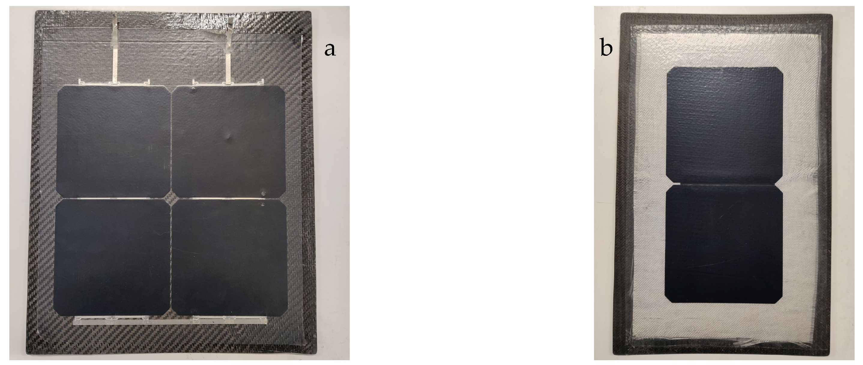
  • Stress Mitigation: The solar cells are attached to the carbon panel only at the edges of the array and remain free to slide over the rest of the surface. This prevents the direct transmission of bending stresses to the solar cells, as they can slide instead of deforming under stress.
  • Electrical Insulation: Unlike carbon fiber, glass fabric is an electrical insulator. By placing the glass fabric between the solar cell array and the carbon fiber panel, the risk of short circuits is eliminated.
Although the use of glass fabric adds weight and thickness, the increase is minimal: only 25 g/m2 in weight and 27 µm in thickness. Adding these values to the results of Table 3, the final configuration has a total thickness of approximately 627 µm and a total weight of 885 g/m2. This solution is the most promising and it will be adopted for the creation of the second prototype.
The steps for this configuration are summarized below:
  • Lamination Process: Solar cells are laminated between two layers of 200 µm TPO and one layer of 50 µm PVF on top.
  • Layer Placement: The layers are arranged in the following order:
    Carbon fiber panel;
    Glass fabric;
    Encapsulated solar cells;
    Peel ply.
  • Vacuum Sealing: The assembly is placed inside a vacuum bag and sealed.
  • Climate Chamber Processing: The vacuum-sealed assembly is placed inside the climate chamber, which is heated to 120 °C. The temperature is maintained for 20 min while the vacuum is continuously applied.
  • Cooling and Removal: The assembly is removed from the climate chamber, cooled and taken out of the vacuum bag. The peel ply is then removed.
This improved configuration ensures reduced thickness and weight, adequate insulation and significantly improved durability under bending stresses, making it the optimal choice for further development.

4. Conclusions and Future Developments

The article analyzed a particularly critical and relevant aspect of developing the second prototype for the RA-Record Aircraft project. The project aims to create an electrically powered UAV entirely powered by solar energy. The study examined various techniques for integrating photovoltaic cell arrays into the aircraft’s wing and tail structures. The selected process should ensure the right balance between weight, thickness and opacity of the external layer to avoid compromising either the aerodynamic profile or the efficiency of the solar cells. The chosen solution involves an initial lamination of the cells onto a polymer film, followed by the adhesion of this film to the load-bearing surface. Particularly important is the placement of a glass fabric layer between the composite panel and the encapsulated cells. This approach reduces the transfer of structural stress to the cells, ensures their electrical insulation and retains the advantages of the general installation methodology. Thanks to the results of this work, the Icarus team can now focus on building the prototype in the immediate future.

Author Contributions

Conceptualization, A.B.; investigation, A.F., C.M.B., G.F., V.I. and B.R.; resources, S.R.; data curation, G.F.; writing—original draft preparation, A.B., C.M.B., G.F., V.I. and B.R.; writing—review and editing, A.A.; visualization, C.M.B., G.F., V.I. and B.R.; supervision, M.D.L.D.V. and A.A.; project administration, G.F. and B.R. All authors have read and agreed to the published version of the manuscript.

Funding

This research received no external funding.

Institutional Review Board Statement

Not applicable.

Informed Consent Statement

Not applicable.

Data Availability Statement

Data are available on request.

Acknowledgments

We want to thank all the members of the production team of the RA project of ICARUS PoliTO for their support in the preparation of the tests.

Conflicts of Interest

Author Simone Regondi was employed by the company Solbian Energie Alternative Srl. The remaining authors declare that the research was conducted in the absence of any commercial or financial relationships that could be construed as a potential conflict of interest.

References

  1. Kivits, R.; Charles, M.B.; Ryan, N. A post-carbon aviation future: Airports and the transition to a cleaner aviation sector. Futures 2010, 42, 199–211. [Google Scholar] [CrossRef]
  2. Kallbekken, S.; Victor, D. A cleaner future for flight—Aviation needs a radical redesign. Nature 2022, 609, 673–675. [Google Scholar] [CrossRef] [PubMed]
  3. Abbe, G.; Smith, H. Technological development trends in Solar-powered Aircraft Systems. Renew. Sustain. Energy Rev. 2016, 60, 770–783. [Google Scholar] [CrossRef]
  4. Rizzo, E.; Frediani, A. A model for solar powered aircraft preliminary design. Aeronaut. J. 2008, 112, 57–78. [Google Scholar] [CrossRef]
  5. Brandt, S.A.; Gilliam, F.T. Design analysis methodology for solar-powered aircraft. J. Aircr. 1995, 32, 703–709. [Google Scholar] [CrossRef]
  6. Charruaz, G.; Borgia, A.; Braghin, A.; Bussi, T.; Esposito, A.; Pescosolido, A. Flight Performance And Dynamics Of An Unconventional Solar Powered Uas. In Proceedings of the 34th Congress of the International Council of the Aeronautical Sciences, ICAS 2024, Florence, Italy, 9–13 September 2024. [Google Scholar]
Figure 1. The latest render of the second solar-powered UAV prototype.
Engproc 90 00057 g001
Figure 2. The ‘Amelia’ prototype, with a focus on the wing and the cells.
Engproc 90 00057 g002
Figure 3. (a) Comparison between peel ply (left), gelcoat (center) and resin (right); (b) glass fiber soaked in resin.
Engproc 90 00057 g003
Figure 4. (a) Glass fiber placed only on top of the cells; (b) an encapsulated array of solar cells.
Engproc 90 00057 g004
Figure 5. Solar cells encapsulated and attached to the carbon fiber panel using the solution (a) of Table 3; (b) with a layer of glass fabric between the panel and the polymeric films.
Engproc 90 00057 g005
Table 1. Thicker films + EVA.
Thickness (µm)Weight (g/m2)
TPO400380
PVF5057
EVA650598
Solar cells (Maxeon® Gen 3)150423
Total16501838
Table 2. Thicker films (no EVA).
Thickness (µm)Weight (g/m2)
TPO400380
PVF5057
Solar cells (Maxeon® Gen 3)150423
Total10001240
Table 3. Thinner films (no EVA).
Thickness (µm)Weight (g/m2)
TPO200190
PVF5057
Solar cells (Maxeon® Gen 3)150423
Total600860
Disclaimer/Publisher’s Note: The statements, opinions and data contained in all publications are solely those of the individual author(s) and contributor(s) and not of MDPI and/or the editor(s). MDPI and/or the editor(s) disclaim responsibility for any injury to people or property resulting from any ideas, methods, instructions or products referred to in the content.

