The Integration of Solar Panels onto a Carbon Fiber Structure for a Solar-Powered UAS †
Abstract
1. Introduction
2. Materials and Methods
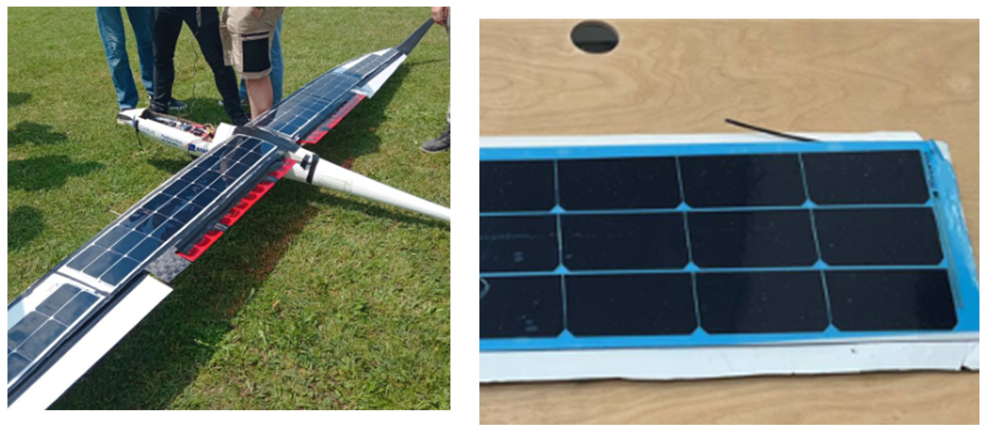
- The simple adhesion of premanufactured solar cell arrays onto the upper wing surface;
- The lamination of solar cells during the manufacturing process of the external wing skin;
- Adhesion using a polymer film.
2.1. Simple Gluing of Pre-Manufactured Arrays of Solar Cells
- The accurate cleaning of the surface to ensure the most effective possible adhesion;
- The insertion of bubble wrap inside the wing structure to prevent excessive loads on the structure during the application of vacuum pressure;
- The adhesion of the solar cell array onto the wing;
- Wing placement in a vacuum bag and application of vacuum pressure to ensure optimal adhesion.
2.2. Lamination of Solar Cells
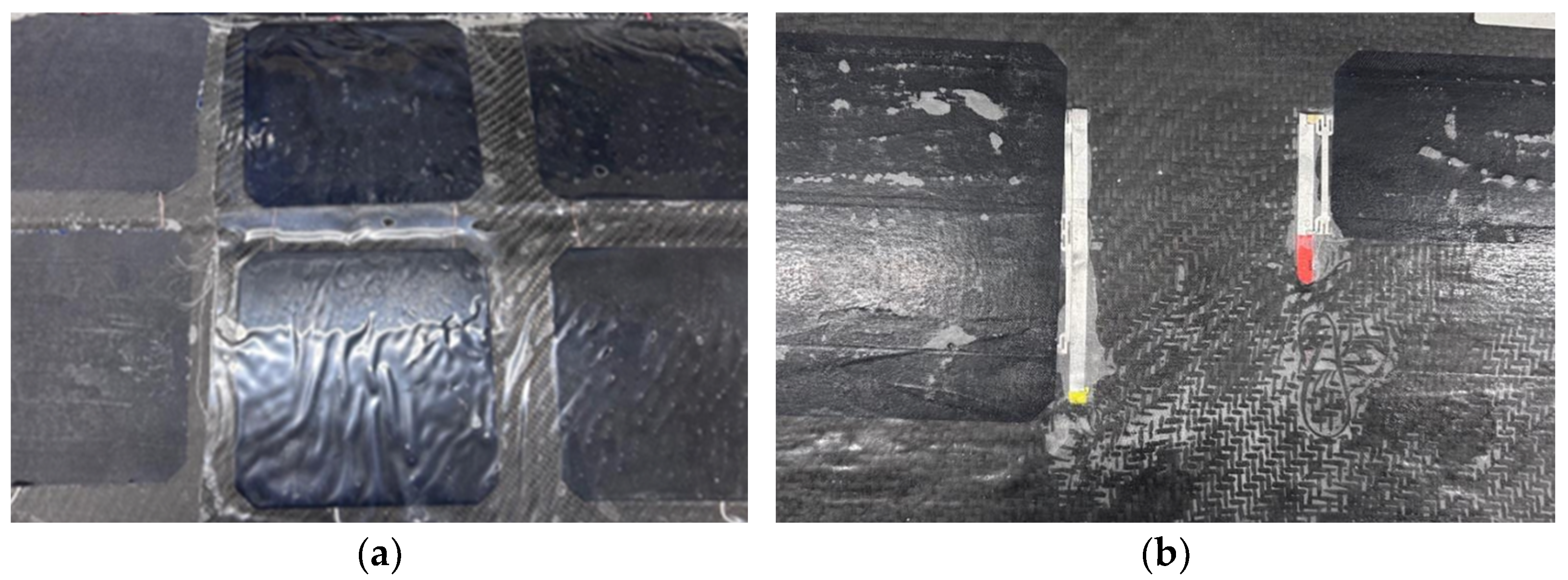
- Gelcoat (Figure 3a) is a transparent gel generally used for the external finishing of composite material products. The results showed a lower final opacity than those obtained with only epoxy resin, but an irregular uniformity on the surface, in addition to a considerable weight;
- Peel ply (Figure 3a) is a semi-transparent fabric generally made of nylon soaked in epoxy resin and hardener. When it was used to cover the cells, the tests showed a very high opacity, a fairly uniform surface finish and a fairly low weight.
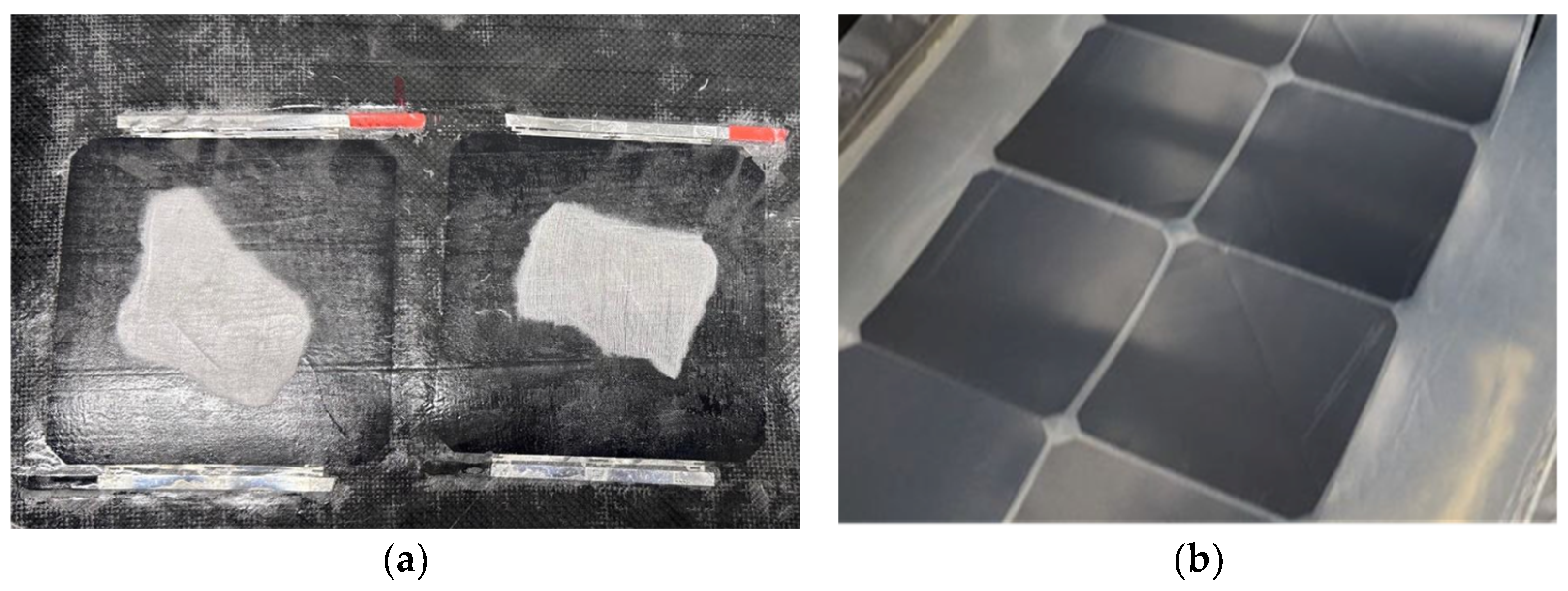
- Glass fiber was used to cover the solar cells, either completely soaked in resin (Figure 3b) or placed only on top of the cells (Figure 4a) while the resin used to impregnate the carbon fiber was still wet. In both cases, the opacity was high, as the resin spread over most of the cells due to capillary action. Additionally, this resulted in a very rough surface finish.
2.3. Integration of Solar Cells with Polymeric Films
- Evacuation Phase: The material stack is placed in the lower chamber of the laminator, then air is pumped out from both the upper and lower chambers, therefore no pressure is applied to the stack during this phase.
- Pressure and Heating Phase: The upper chamber valve is released, allowing a controlled amount of air to enter. This incoming air applies the desired pressure onto the stack, increasing the heat conduction from the heated plates. The temperature rises quickly and stabilizes between 130 °C and 150 °C, according to the specifications of the encapsulation material used.
- Cooling Phase: After the encapsulant is fully processed, the panel is removed from the chambers and the panel is cooled down to approximately 80 °C by means of force convection.
3. Results and Discussion
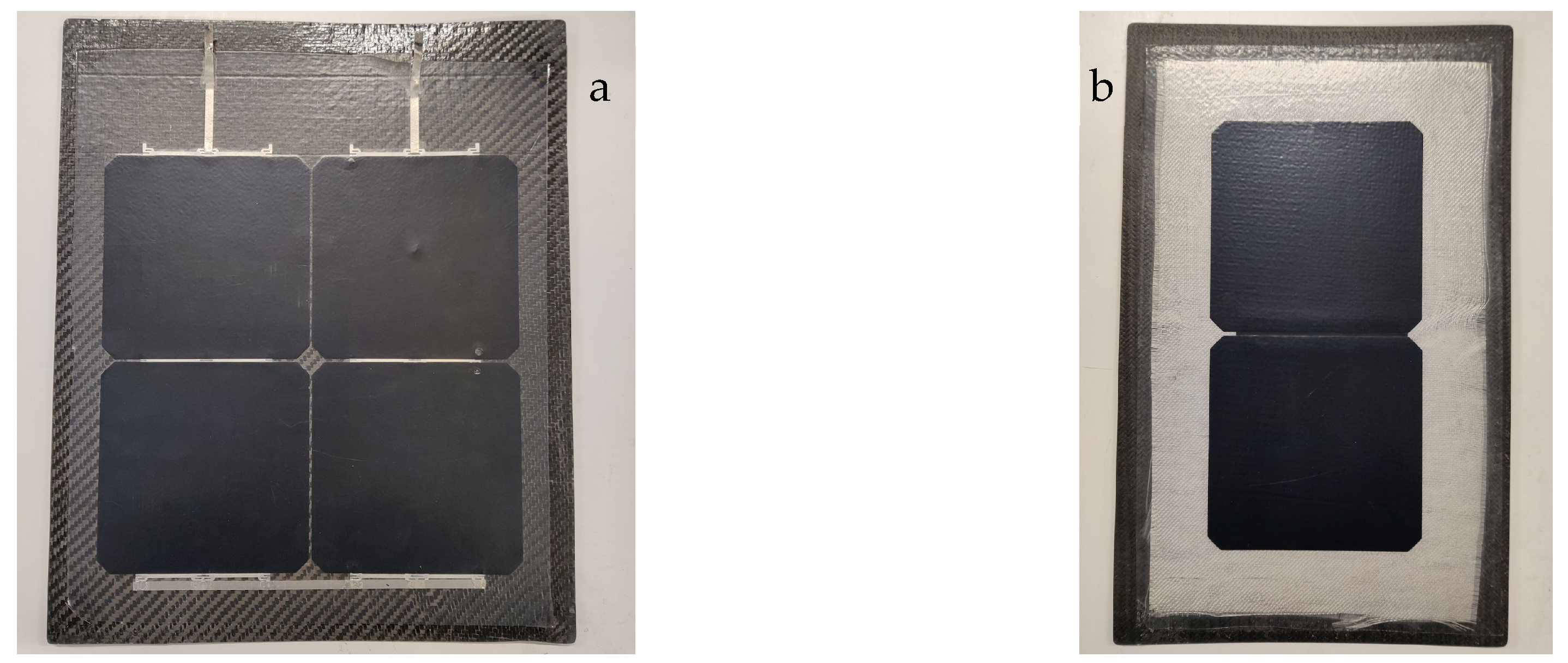
- Stress Mitigation: The solar cells are attached to the carbon panel only at the edges of the array and remain free to slide over the rest of the surface. This prevents the direct transmission of bending stresses to the solar cells, as they can slide instead of deforming under stress.
- Electrical Insulation: Unlike carbon fiber, glass fabric is an electrical insulator. By placing the glass fabric between the solar cell array and the carbon fiber panel, the risk of short circuits is eliminated.
- Lamination Process: Solar cells are laminated between two layers of 200 µm TPO and one layer of 50 µm PVF on top.
- Layer Placement: The layers are arranged in the following order:
- ○
- Carbon fiber panel;
- ○
- Glass fabric;
- ○
- Encapsulated solar cells;
- ○
- Peel ply.
- Vacuum Sealing: The assembly is placed inside a vacuum bag and sealed.
- Climate Chamber Processing: The vacuum-sealed assembly is placed inside the climate chamber, which is heated to 120 °C. The temperature is maintained for 20 min while the vacuum is continuously applied.
- Cooling and Removal: The assembly is removed from the climate chamber, cooled and taken out of the vacuum bag. The peel ply is then removed.
4. Conclusions and Future Developments
Author Contributions
Funding
Institutional Review Board Statement
Informed Consent Statement
Data Availability Statement
Acknowledgments
Conflicts of Interest
References
- Kivits, R.; Charles, M.B.; Ryan, N. A post-carbon aviation future: Airports and the transition to a cleaner aviation sector. Futures 2010, 42, 199–211. [Google Scholar] [CrossRef]
- Kallbekken, S.; Victor, D. A cleaner future for flight—Aviation needs a radical redesign. Nature 2022, 609, 673–675. [Google Scholar] [CrossRef] [PubMed]
- Abbe, G.; Smith, H. Technological development trends in Solar-powered Aircraft Systems. Renew. Sustain. Energy Rev. 2016, 60, 770–783. [Google Scholar] [CrossRef]
- Rizzo, E.; Frediani, A. A model for solar powered aircraft preliminary design. Aeronaut. J. 2008, 112, 57–78. [Google Scholar] [CrossRef]
- Brandt, S.A.; Gilliam, F.T. Design analysis methodology for solar-powered aircraft. J. Aircr. 1995, 32, 703–709. [Google Scholar] [CrossRef]
- Charruaz, G.; Borgia, A.; Braghin, A.; Bussi, T.; Esposito, A.; Pescosolido, A. Flight Performance And Dynamics Of An Unconventional Solar Powered Uas. In Proceedings of the 34th Congress of the International Council of the Aeronautical Sciences, ICAS 2024, Florence, Italy, 9–13 September 2024. [Google Scholar]


| Thickness (µm) | Weight (g/m2) | |
|---|---|---|
| TPO | 400 | 380 |
| PVF | 50 | 57 |
| EVA | 650 | 598 |
| Solar cells (Maxeon® Gen 3) | 150 | 423 |
| Total | 1650 | 1838 |
| Thickness (µm) | Weight (g/m2) | |
|---|---|---|
| TPO | 400 | 380 |
| PVF | 50 | 57 |
| Solar cells (Maxeon® Gen 3) | 150 | 423 |
| Total | 1000 | 1240 |
| Thickness (µm) | Weight (g/m2) | |
|---|---|---|
| TPO | 200 | 190 |
| PVF | 50 | 57 |
| Solar cells (Maxeon® Gen 3) | 150 | 423 |
| Total | 600 | 860 |
Disclaimer/Publisher’s Note: The statements, opinions and data contained in all publications are solely those of the individual author(s) and contributor(s) and not of MDPI and/or the editor(s). MDPI and/or the editor(s) disclaim responsibility for any injury to people or property resulting from any ideas, methods, instructions or products referred to in the content. |
© 2025 by the authors. Licensee MDPI, Basel, Switzerland. This article is an open access article distributed under the terms and conditions of the Creative Commons Attribution (CC BY) license (https://creativecommons.org/licenses/by/4.0/).
Share and Cite
Aimasso, A.; Vedova, M.D.L.D.; Bruggi, C.M.; Borgia, A.; Facci, A.; Ferrero, G.; Ingrosso, V.; Ravenna, B.; Regondi, S. The Integration of Solar Panels onto a Carbon Fiber Structure for a Solar-Powered UAS. Eng. Proc. 2025, 90, 57. https://doi.org/10.3390/engproc2025090057
Aimasso A, Vedova MDLD, Bruggi CM, Borgia A, Facci A, Ferrero G, Ingrosso V, Ravenna B, Regondi S. The Integration of Solar Panels onto a Carbon Fiber Structure for a Solar-Powered UAS. Engineering Proceedings. 2025; 90(1):57. https://doi.org/10.3390/engproc2025090057
Chicago/Turabian StyleAimasso, Alessandro, Matteo D. L. Dalla Vedova, Carlotta M. Bruggi, Alessandro Borgia, Andrea Facci, Giovanni Ferrero, Vito Ingrosso, Bianca Ravenna, and Simone Regondi. 2025. "The Integration of Solar Panels onto a Carbon Fiber Structure for a Solar-Powered UAS" Engineering Proceedings 90, no. 1: 57. https://doi.org/10.3390/engproc2025090057
APA StyleAimasso, A., Vedova, M. D. L. D., Bruggi, C. M., Borgia, A., Facci, A., Ferrero, G., Ingrosso, V., Ravenna, B., & Regondi, S. (2025). The Integration of Solar Panels onto a Carbon Fiber Structure for a Solar-Powered UAS. Engineering Proceedings, 90(1), 57. https://doi.org/10.3390/engproc2025090057


