Proceeding Paper

A Parametric Comparison of JARUS SORA 2.0 and 2.5 Ground Risk Models †

by
Alejandro del Estal Herrero
1,
Nathanel Apter
2 and
Stefan Hristozov
3,4,*
1
RigiTech, 1008 Prilly, Switzerland
2
UASolutions, 1530 Payerne, Switzerland
3
Institute of Robotics, Bulgarian Academy of Science (BAS), 1113 Sofia, Bulgaria
4
Unmanned Systems Bulgaria, 1113 Sofia, Bulgaria
*
Author to whom correspondence should be addressed.
Presented at the 14th EASN International Conference on “Innovation in Aviation & Space towards sustainability today & tomorrow”, Thessaloniki, Greece, 8–11 October 2024.
Eng. Proc. 2025, 90(1), 47; https://doi.org/10.3390/engproc2025090047
Published: 14 March 2025

Abstract

:
This paper provides a comparative analysis of the Joint Authorities for Rulemaking of Unmanned Systems (JARUS)’ Specific Operations Risk Assessment (SORA) ground risk model, between Version 2.0 and Version 2.5, focusing on differences and similarities. SORA, a methodology for risk assessment and conformity evaluation developed by JARUS, has been widely adopted across various regions, including Australia, Canada, the European Union, and others. The study delves into the variations in risk assessment outcomes concerning intrinsic and final Ground Risk Class, elucidating their implications for different categories of Unmanned Aircraft Systems (UASs). Key paradigm shifts between SORA 2.0 and 2.5 affecting Ground Risk assessment are outlined, as follows: (1) Introduction of quantitative analysis based on precise population density for determining intrinsic Ground Risk Class. (2) Incorporation of Visual Line of Sight (VLOS) from the remote pilot as a mitigation measure, coupled with a stricter definition of VLOS as visual ground control. (3) Enhanced differentiation among UAS sizes. Furthermore, the paper underscores the implications of these changes on original equipment manufacturers (OEM) and operators. By referencing standard industry operations, the analysis sheds light on how modifications in the SORA methodology impact UAS operations and regulatory compliance. Overall, this comparative analysis provides valuable insights into the evolution of the SORA ground risk model, facilitating a deeper understanding of its application in UAS operations and regulatory frameworks globally.
Keywords:
JARUS; SORA; GRC; iGRC

1. Introduction

Rapid advances in Unmanned Aircraft System (UAS) technology have significantly impacted their use across various fields, such as inspection [1], surveillance, and delivery missions [2]. Despite the numerous advantages, operational safety remains a critical issue due to several risk factors inherent in each operation. Consequently, performing a thorough risk assessment is essential. The primary risks during UAS-assisted missions include fatal injuries to third parties on the ground; collisions with third parties in the air; and damage to critical infrastructure.
In the specific category of UAS operation, conducting a risk assessment before the flight is mandatory for operators. To facilitate this process, the Joint Authorities for the Rulemaking of Unmanned Systems (JARUS) has developed the SORA (Specific Operational Risk Assessment) methodology [3,4]. This methodology has been recognised and approved by several other aviation authorities such as the Australian CASA, Canadian Transport Canada, the European Union Aviation Safety Agency (EASA) [5], and a few others, as a comprehensive risk assessment tool.
The SORA methodology provides a structured framework for risk assessment in UAS operations. It consists of a step-by-step procedure designed to identify and evaluate risks related to both ground and air. The process aims to determine the necessary mitigation actions to achieve the desired level of safety, known as the Specific Assurance and Integrity Level (SAIL). The SAIL helps in identifying the level of robustness required for operational safety objectives (OSOs). The OSOs are specific goals related to maintaining operational safety and minimising risk during UAS missions.
The SORA methodology comprises ten systematic steps, each crucial for evaluating the safety aspects of UAS operations. They are delineated along with their significance within the framework in the next point. By adhering to these systematic steps, the SORA methodology facilitates a rigorous assessment of UAS operations, ensuring safety and regulatory compliance. The methodology can be applied with the same level of success by state actors operating UASs [6,7].
The paper is organised as follows. Section 2 presents an overview of the SORA process and the changes introduced with SORA 2.5; Section 3 presents some of the considered use-cases in this analysis; and Section 4 opens up discussion on some of the major findings. Finally, Section 5 presents the conclusions and directions of future work.

2. Overview of SORA Process and Changes Between SORA 2.0 and 2.5

Step #1—Documentation of Proposed Operations: Elements that could lead to confusion have been removed from this step, which now serves as an actual foundational tool for communication between the applicant and the competent authority. Which documents should be presented to the competent authority has been clarified. These documents elucidate the nature of the UAS’s operation, including flight path details, airspace type, and population density overflown.
Step #2—Intrinsic Ground Risk Class (iGRC): The determination of iGRC, on a scale from 1 to 11, is defined and is now related to unmanned aircraft (UA) characteristics and population density. This assessment is conducted for both the area at risk and its adjacent region:
  • Two more classes are introduced for 20 m and 40 m UAs;
  • Maximum speed replaces kinetic energy;
  • The difference between VLOS/BVLOS is no longer present in this step;
  • Both quantitative and qualitative population density descriptions are allowed, with more examples given;
  • A UA weighing less than or equal to 250 g and having a maximum speed less or equal to 25 m/s is considered to have an iGRC of 1, regardless of the population density.
Step #3—Final Ground Risk Class: Considering some new strategic mitigations, the Final GRC is calculated, which is crucial for evaluating the potential fatality risks associated with the operation.
  • M1—Strategic mitigations for ground risk, has been split up into:
    M1(A)—Sheltering: used to be part of M1 under SORA 2.0;
    M1(B)—Operational restrictions: used to be part of M1 under SORA 2.0; and
    M1(C) Tactical mitigations—Ground observation: it was part of Step #2 under SORA 2.0, and has received some modifications in SORA 2.5, such as allowing the use of technical means. Additional reductions may be claimed based on the ablity to observe the ground area where the operation takes place, so that the number of uninvolved people flown over during the operation may be significantly reduced.
The maximum reduction in GRC by M1 mitigations is now 3 instead of 4.
  • M2—Effects of UA ground impact are reduced: they still exist, as they used to in SORA 2.0.
  • M3—An emergency response plan (ERP) is in place, the UAS operator is validated and effective: has been moved to OSO #08 in Step #9.
Step #4—Initial Air Risk Class (ARC): Assessment of ARC, conducted qualitatively, involves evaluating airspace characteristics identified in Step #1. Parameters defining ARC categories include airspace type, altitude, and urbanisation levels.
Step #5—Residual Air Risk Class: Following strategic mitigations, this step determines the Residual Air Risk Class, aiming to reduce the initial risk level associated with mid-air collisions.
Step #6—Tactical Mitigation Performance Requirement (TMPR) and Robustness Levels: Tactical mitigations are implemented during operations to mitigate residual risks. TMPRs address various functional aspects crucial for risk mitigation.
Step #7—SAIL Determination: Utilising outputs from previous steps, SAIL is determined to gauge the operational integrity and assurance level required for UAS operation.
Step #8—Identification of Containment Requirements (moved from Step #9 in SORA 2.0 to Step #8 in SORA 2.5): This step focuses on assessing risks posed by operational loss of control, referring to containment design features and operational procedures to mitigate potential hazards. Both the triggers for containment and the levels of containment, including their requirements, have changed. The level of containment is now determined based on the maximum characteristic dimension, the maximum speed, the average population density in the adjacent area, the outdoor assemblies of people allowed within 1 km of the operational volume, and the SAIL. Containment levels are now changed from basic or enhanced containment in SORA 2.0 to low, medium, or high levels of containment in SORA 2.5.
Step #9—Identification of OSOs: Based on the assigned SAIL, OSOs are identified, specifying integrity and assurance levels required for various operational aspects, including UAS technical functionalities and human factors.
Step #10—Comprehensive Safety Portfolio: This final step involves compiling a comprehensive safety portfolio comprising all necessary documents and compliance evidence, ensuring alignment with SORA requirements. Any discrepancies may necessitate adjustments to the proposed operation or additional evidence for compliance.

3. Use Cases

In the following examples Table 1, Table 2 and Table 3 and Figure 1, Figure 2 and Figure 3), the use of M3 mitigations is neglected (assumed to be medium in SORA 2.0; i.e., the GRC is not affected by it). The evaluation of the air risk within the operational volume is neglected (it is assumed that it can be mitigated up to the maximum ARC as per the SAIL of the operation). Additionally, it is assumed that the adjacent areas can be defined in both cases as per SORA 2.5. For clarity, the terms “basic” and “enhanced” are replaced by “low” and “medium”. Adjacent population areas are estimated manually based on the nature of the surrounding populated environments and population density maps. It is assumed that the UA used in the examples belongs to the equivalent column from the iGRC table.
While not derived directly from real operations, the examples are prepared based on the experience of the authors with real operations, and presented to JARUS Working Group Safety and Risk Management.

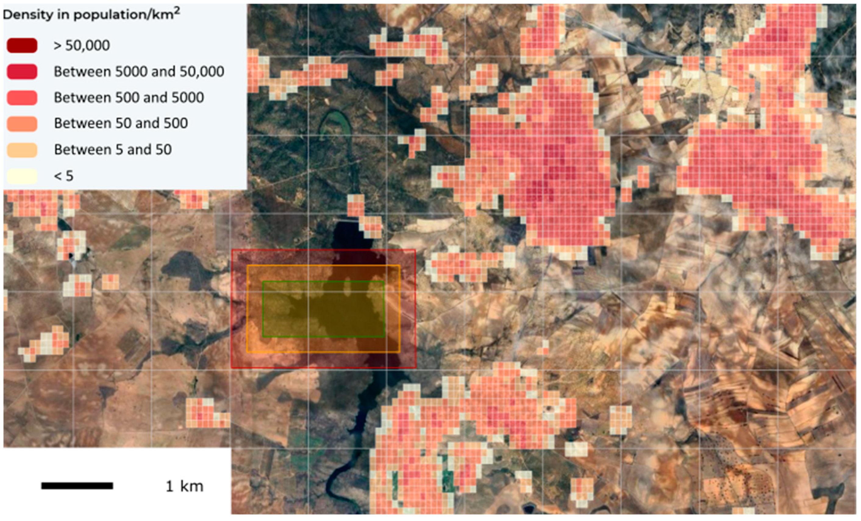
3.1. Example 1—Operation in Uncontrolled Airspace in Rural Environment

UA:
Mass: 25 kg
Characteristic dimension: <3 m
Maximum speed: <35 m/s
Configuration 1:Configuration 2:
MulticopterFixed-wing:
VLOSBVLOS
Adjacent area: 5 kmAdjacent area: 9 km
Population: sparsely populated/<5 ppl/km2

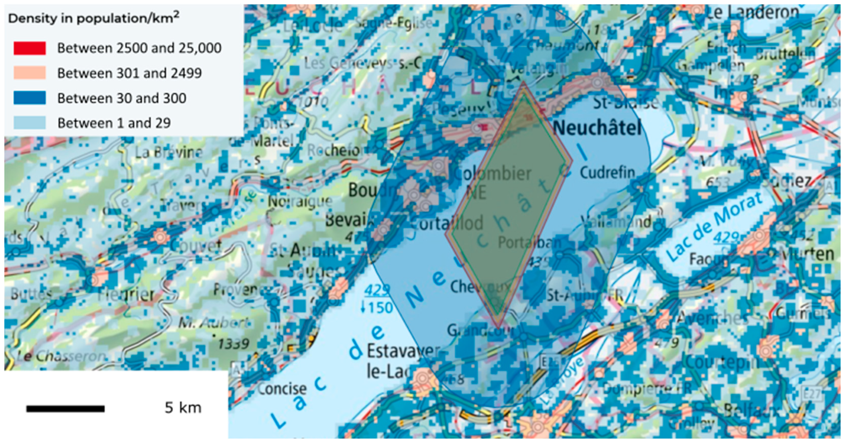
3.2. Example 2—BVLOS Long-Range Operation in Controlled Airspace in Urban Environment

UA:
Characteristic dimension: < 8 m;
Maximum speed: < 75 m/s;
Configuration:
Fixed-wing in BVLOS;
Adjacent area: 9 km;
Population: populated/<5000 ppl/km2.

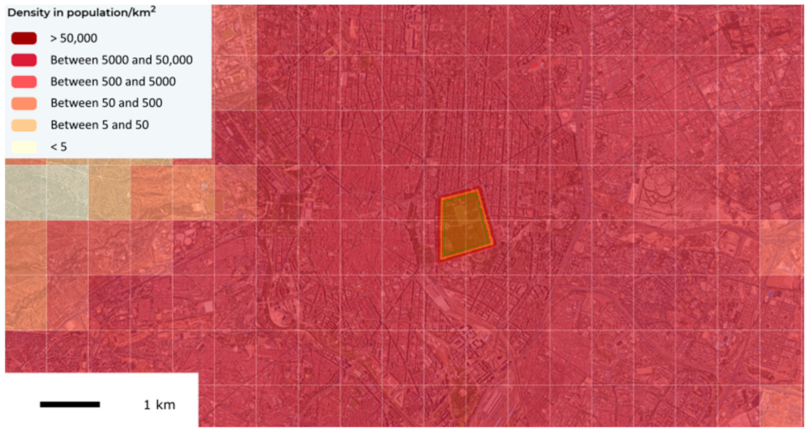
3.3. Example 3—VLOS Short-Range Operation in Controlled Airspace in Urban Environment

UA:
Characteristic dimension: < 1 m;
Maximum speed: < 25 m/s;
Configuration:
Multicopter in BVLOS;
Adjacent area: 5 km;
Population: populated/<50,000 ppl/km2.

4. Major Findings and Discussion

In order to clearly measure the difference between the intrinsic Ground Risk Class model in the JARUS SORA 2.0 and the JARUS SORA 2.5 framework, intrinsic Ground Risk Class equivalents for each population density band and UAS characteristic size were computed for both VLOS and BVLOS cases.
The results are documented in Table 4 and Table 5. In general, the iGRC with the SORA 2.5 tends to be higher than the iGRC with the SORA 2.0. The iGRC is especially increased for UA smaller than 1 m, smaller than 3 m, and between 20 and 40 m.
In VLOS (Table 5), in controlled ground areas, the iGRC is generally lower with the new SORA 2.5 iGRC model. For population densities between 5 and 50,000 ppl/km2, the iGRC of SORA 2.5 is almost always higher than the iGRC of SORA 2.0.
The difference in iGRC can go up to three points. This will, in part, be compensated by the introduction of the mitigation M1(C), which allows for one point of mitigation in the final GRC, which is equivalent to the variation between VLOS and BVLOS operations in SORA 2.0 (although procedural requirements are now defined explicitly). Since options for mitigations are generally enhanced in SORA 2.5, applicants will generally tend to make more use of those (M1(A), M1(B), and M1(C)) to reduce the difference in GRC that could occur when switching from SORA 2.0 to SORA 2.5. The possibility of combining multiple partial mitigations is also explicitly defined.

5. Conclusions

The publication of SORA 2.5 from JARUS comes with both opportunities and challenges for the UAS operators, OEMs, and National Aviation Authorities (NAAs) alike. While the updated framework relieves some operations, it may impose new obstacles on others, especially in cases involving SAIL II UAs under 1 kg or those operating in areas with a population density that is on the higher end of those seen for sparsely populated regions.
New business opportunities should arise with the new version, especially for small UASs under 250 g or operations over controlled ground areas. However, existing or currently developing businesses with UAS operations, particularly those conducting BVLOS operations, may encounter difficulties in continuing their missions under the new SORA guidelines.
To address these challenges, applicants will likely need to implement more of the mitigation measures included in SORA, which will increase the documentation workload for both operators and NAAs. On the positive side, the simplified classification of areas as either sparsely populated or populated may ease some regulatory burdens.
To counteract the potential obstacles presented by SORA 2.5, several measures could be considered:
  • Ease the use of M1(B) and M1(C) mitigations: Greater flexibility in the application of reduced exposure time arguments during the early stages of SORA 2.5 implementation could help operators adapt. These arguments could later be removed when the UAS industry becomes more mature and capable of deploying higher SAIL operations.
  • Expand the use of M2 mitigations: Given the improved practises which were developed following the release of EASA MOC Light-UAS.2512-01 by EASA [8], easing in the use of partial M2 mitigations could prove critical for certain operations. Flexibility in applying these mitigations may be especially important for missions like inspections and agriculture, which often involve very low-altitude flights and represent the biggest portion of UAS operations at the moment.
  • Reevaluate population density grid resolution: Although not considered in the current article, the grid cell sizes used for population density in SORA 2.5 are not well-suited for very low-altitude operations. Adjustments to these grid sizes are essential to support current inspection and agricultural missions effectively.
Although SORA 2.5 offers greater clarity and certainty for applicants and NAAs, the new framework will introduce challenges that need to be managed. Therefore, we recommend allowing the continued use of SORA 2.0 during a transitional period of a few years to ensure a smoother transition for all stakeholders involved.

Author Contributions

Conceptualization, A.d.E.H., N.A. and S.H.; methodology, A.d.E.H., N.A. and S.H.; software, A.d.E.H., N.A. and S.H.; validation, A.d.E.H., N.A. and S.H.; formal analysis, A.d.E.H., N.A. and S.H.; investigation, A.d.E.H., N.A. and S.H.; resources, A.d.E.H., N.A. and S.H.; data curation, A.d.E.H., N.A. and S.H.; writing—original draft preparation, A.d.E.H., N.A. and S.H.; writing—review and editing, A.d.E.H., N.A. and S.H.; visualization, A.d.E.H., N.A. and S.H.; supervision, A.d.E.H., N.A. and S.H.; project administration, A.d.E.H., N.A. and S.H.; funding acquisition, A.d.E.H., N.A. and S.H. All authors have read and agreed to the published version of the manuscript.

Funding

This research received no external funding.

Institutional Review Board Statement

Not applicable.

Informed Consent Statement

Not applicable.

Data Availability Statement

Data are contained within the article.

Conflicts of Interest

Author Alejandro del Estal Herrero was employed by the company RigiTech. Author Nathanel Apter was employed by the company UASolutions. Author Stefan Hristozov was employed by the company Unmanned Systems Bulgaria. The remaining authors declare that the research was conducted in the absence of any commercial or financial relationships that could be construed as a potential conflict of interest.

References

  1. Martinez, C.; Sanchez-Cuevas, P.J.; Gerasimou, S.; Bera, A.; Olivares-Mendez, M.A. SORA Methodology for Multi-UAS Airframe Inspections in an Airport. Drones 2021, 5, 141. [Google Scholar] [CrossRef]
  2. Hidayat, R.; Jenie, Y.I. Implementation of SORA Methodology Version 2.5 for Medical Delivery Using Quadrotor UAS in Remote Areas. War. Penelit. Perhub. 2024, 35, 77–91. [Google Scholar] [CrossRef]
  3. JARUS. JARUS Guidelines on Specific Operations Risk Assessment (SORA) V2.0. Available online: http://jarus-rpas.org/wp-content/uploads/2023/07/jar_doc_06_jarus_sora_v2.0.pdf (accessed on 18 October 2024).
  4. JARUS. JARUS Guidelines on Specific Operations Risk Assessment (SORA) V2.5. Available online: http://jarus-rpas.org/wp-content/uploads/2024/06/SORA-v2.5-Main-Body-Release-JAR_doc_25.pdf (accessed on 18 October 2024).
  5. EASA. Easy Access Rules for Unmanned Aircraft Systems (Regulations (EU) 2019/947 and 2019/945). Available online: https://www.easa.europa.eu/en/document-library/easy-access-rules/easy-access-rules-unmanned-aircraft-systems-regulations-eu (accessed on 18 October 2024).
  6. Stanev, H.; Hristozov, S. Applicability of JARUS SORA to State UAS Operations in Disaster Relief. ETR 2024, 4, 244–250. [Google Scholar] [CrossRef]
  7. Janik, P.; Zawistowski, M.; Fellner, R.; Zawistowski, G. Unmanned Aircraft Systems Risk Assessment Based on SORA for First Responders and Disaster Management. Appl. Sci. 2021, 11, 5364. [Google Scholar] [CrossRef]
  8. EASA. Means of Compliance with Light-UAS.2512. Available online: https://www.easa.europa.eu/en/downloads/137609/en (accessed on 18 October 2024).
Figure 1. Operational volume at Embalse del Guajaraz (Toledo, Spain). Green: flight geography. Yellow: contingency volume. Red: ground risk buffer. Our own elaboration, based on a population density map. Tool: RigiCloud v1.14.0 (made by RigiTech). Population density source: GHS-POP (R2023), made with Copernicus.
Engproc 90 00047 g001
Figure 2. Operational volume at Lac de Neuchâtel (Neuchâtel—Fribourg, Switzerland). Our own elaboration based on a drone restrictions map.
Engproc 90 00047 g002
Figure 3. Operational volume at Parque del Retiro (Madrid, Spain). Green: flight geography. Yellow: contingency volume. Red: ground risk buffer. Our own elaboration based on a population density map. Tool: RigiCloud v1.14.0 (made by RigiTech). Population density source: GHS-POP (R2023), made w Copernicus.
Engproc 90 00047 g003
Table 1. Comparison of SORA 2.0 and 2.5 parameters for Example 1.
SORA 2.0SORA 2.5
UAMulticopterFixed-wingMulticopterFixed-wing
iGRC3433
M1NoNoNoNo
M2NoNoNoNo
Final GRC3433
SAILIIIIIIIII
Adjacent population density
(irrelevant in SORA 2.0)
<500 ppl/km2
(sheltering assumed)
<5000 ppl/km2
(sheltering possible)
Adjacent ARC-d
(irrelevant in SORA 2.5)
NoNo
Containment requirementsLowMediumSAIL II UAS:
LowMedium
SAIL III and above UAS:
LowMedium
Table 2. Comparison of SORA 2.0 and 2.5 parameters for Example 3.
SORA 2.0SORA 2.5
iGRC87
M1−1−1
M2−1−1
Final GRC65
SAILVIV
Adjacent population density
(irrelevant in SORA 2.0)
<5000 ppl/km2
(sheltering not possible)
Adjacent ARC-d
(irrelevant in SORA 2.5)
Yes
Adjacent assemblies of people (<1 km only in SORA 2.5)Not assessedNot assessed
Containment requirementsMediumSAIL III and above UAS:
Medium
Table 3. Comparison of SORA 2.0 and 2.5 parameters for Example 4.
SORA 2.0SORA 2.5
UAMulticopter>250 g<250 g
iGRC461
M1−1−1N/A
M2NoNoNo
Final GRC351
SAILIIIVII
Adjacent population density
(irrelevant in SORA 2.0)
<50,000 ppl/km2
(sheltering assumed)
<50,000 ppl/km2
(sheltering possible)
Adjacent ARC-d
(irrelevant in SORA 2.5)
Yes
Adjacent assemblies of people (<1 km only in SORA 2.5)YesYes
40,000 to 400,000
Yes
40,000 to 400,000
Containment requirementsMediumSAIL II UAS:
MediumLow
SAIL III and above UAS:
LowLow
Table 4. Comparison of the SORA 2.0 and 2.5 model for the VLOS UAS operational scenario cases.
Size<1 m<3 m<8 m<20 m<40 m
Population density
VLOS assumed
2.02.5Δ2.02.5Δ2.02.5Δ2.02.5Δ2.02.5Δ
Controlled G. Area.11021−132−143−143−1
Sparsely<5220330440550561
<50231341451561572
<500242352462572583
Populated<5000451561671880891
<50,0004625726828918102
Assembly>50,000/Assembly770N/A8N/AN/AN/AN/AN/AN/AN/AN/AN/AN/A
Table 5. Comparison of the SORA 2.0 and 2.5 model for the BVLOS UAS operational scenario cases.
Size<1 m<3 m<8 m<20 m<40 m
Population density
BVLOS assumed
2.02.5Δ2.02.5Δ2.02.5Δ2.02.5Δ2.02.5Δ
Controlled G. Area.11021−132−143−143−1
Sparsely<532−143−154−165−1660
<50330440550660671
<500341451561671682
Populated<500055066087−1108−2109−1
<50,000561671880109−110100
Assembly>50,000/Assembly87−1N/A8N/AN/AN/AN/AN/AN/AN/AN/AN/AN/A
Disclaimer/Publisher’s Note: The statements, opinions and data contained in all publications are solely those of the individual author(s) and contributor(s) and not of MDPI and/or the editor(s). MDPI and/or the editor(s) disclaim responsibility for any injury to people or property resulting from any ideas, methods, instructions or products referred to in the content.

