1. Introduction
Inertial Measurement Units (IMUs) collect data that are extracted for navigation solutions. The simplest models are examples of dead reckoning, which is any method of navigation that sums measurements of distance traveled or integrates measurements of velocity to calculate distance via known inputs or estimated user step length and a heading measurement [
1]. In pedestrian dead reckoning (PDR), a position and heading are derived by measuring specific force and angular rate with a microelectromechanical systems (MEMS) IMU attached in a minimally invasive manner so as to not disrupt the natural gait [
2]. With a known starting point, heading and distance, an estimation of each step and position of the pedestrian can be calculated. However, there are limitations involved when relying solely on PDR navigation. These limitations include an increase in error bounds, or the area where it is statistically possible to be located for all detected steps [
3]; the magnetometer and gyroscope heading output is susceptible to magnetic interference, and without heading corrections the solution succumbs to magnetic disturbances and drift [
4]; and poor-quality sensors used in MEMS IMUs lead to drift in the heading solution.
Foot-mounted inertial navigation can achieve high accuracy from poor-quality sensors by performing zero velocity updates (ZVUs) every step [
5]. ZVUs keep sensors calibrated and minimize drift in the position solution. To obtain the best performance, the ZVU algorithm needs to be carefully tuned [
3]. ZVU algorithms are used for pedestrian navigation by collecting inertial data with an IMU and identifying zero velocity intervals [
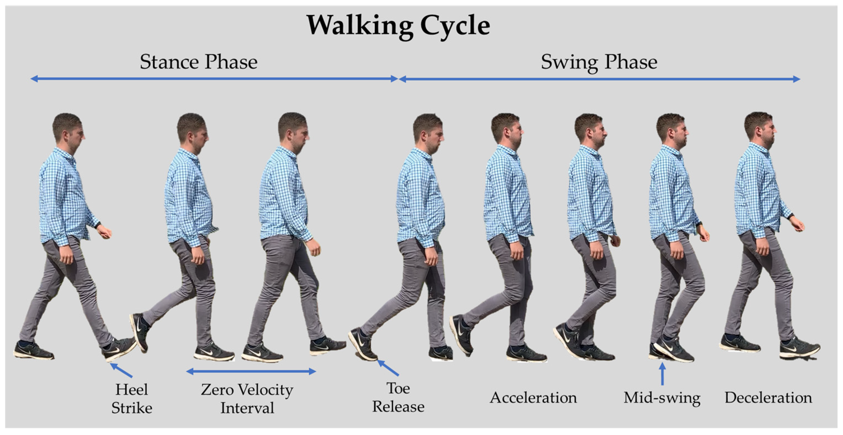
6] when the IMU is briefly stationary. Stationary pedestrian detection relies on the walking cycle, where the foot is constantly accelerating or decelerating. The walking cycle is divided into the stance and swing phases [
7]. The stance phase is the period of time when the foot is in contact with the ground, from the heel strike to the heel release [
8]. The swing phase is the duration of the foot leaving the ground until the same foot touches the ground again [
9].
Figure 1 is an example of one cycle of the two phases in the walking cycle. Stationary detection occurs during the stance phase. The stationary period is also known as a zero velocity interval (ZVI), and historically this was assumed to be about 0.2 s within an entire walking cycle of about 1.14 s [
10]. When the accelerometer or gyroscope measurements are below a test quantity, computed from a specified moving window of time, the foot is assumed to be stationary. One accepted threshold value is below the magnitude of 1.239 m/s
2 for the MEMs accelerometers, where the value of gravity is factored out of consideration [
11]. The threshold value comes from empirical data and the calculation of acceleration from the average force of the heel strike [
12].
In addition to ZVU-aided inertial navigation algorithms, a zero angular rate update (ZARU) can be performed in conjunction with ZVUs. ZARUs are similar to ZVUs, because they help keep sensors calibrated and aligned during the walking cycle when the angular rate measured is below a specific threshold. ZARUs can be utilized in addition to a ZVU but not as an independent inertial navigation algorithm [
3].
The identification of ZVIs and the zero angular rate during the walking cycle is difficult because the foot tends to rotate during the stance phase. The rotation of the foot varies between individual, shoe style and terrain. Thus, some parts of the foot are more stationary than others. Identifying the ZVIs and zero angular rates is accomplished using MEMS IMUs, similar to how context detection is used to decipher pedestrian activities [
13]. Previous work has shown that in addition to using context detection for identifying pedestrian behavior, data recorded from MEMS IMUs can determine the varying terrains over which a pedestrian has traveled. This suggests that the walking cycle and natural gait of a pedestrian is affected by the terrain [
14]. Studies have shown that there are changes in pedestrian speed across differing terrains [
11,
15,
16], suggesting that the natural gait of the walking cycle is affected. Most work on foot-mounted inertial navigation has been conducted indoors on hard surfaces [
17,
18], but a reliable system needs to work effectively both indoors and outdoors on a variety of different surfaces.
Similar to a human’s ability to use sensory awareness in determining terrain while walking due to differences experienced in the gait cycle, a ZVU navigation solution must account for this difference. Human sensory awareness determines changes in terrain type while walking, and work by Knuth and Groves verified that inertial data can be used to differentiate between terrains with 99.24% accuracy using a k-Nearest Neighbor machine learning algorithm [
14]. If the natural gait is affected, then the differences will be recorded by the IMU, and ZVU navigation algorithms should be tuned for differences to the gait.
Existing ZVU and ZARU navigation algorithms are limited by using predetermined thresholds and tuning parameters to determine accuracy, such as acceleration moving variance detectors [
19], acceleration magnitude detectors [
20], angular rate energy detectors [
21] and the duration of ZVIs [
10]. Conventionally, these parameters are used regardless of terrain type. If differences are experienced while walking across different terrains, then these differences affect ZVU-aided inertial navigation solutions.
In order to determine how differences in terrain affect the navigation solution, an investigation on how parameters to existing ZVU and ZARU algorithms are used is needed. Furthermore, an examination into additional parameters is required to accommodate differences in terrain from sensory awareness. For comparisons, OpenShoe, an opensource ZVU-aided inertial navigation algorithm for use with foot-mounted IMUs, is used throughout as a navigation algorithm [
22] and modified to include terrain-dependent parameters. For ZVUs, the threshold is calculated from the magnitude of the three-axis accelerometer during the ZVI. In this paper, a test statistic is used to account for gravity in the accelerometer magnitude threshold. Equation (1) converts the raw data into test data:
The ZARU threshold is calculated from the magnitude of the three-axis gyroscope during the stance phase. Finally, the last parameters are the time of a complete cycle and duration of the ZVI. This accounts for the time between each step, including the ZVI, and sets a timing threshold where a step is not measured without a wait period. A visualization of the thresholds during the walking cycle is shown in
Figure 2 by applying a moving average filter to help with the conceptualization; the data were collected from a single user using a MEMS IMU to demonstrate the walking cycle on concrete.
2. Materials and Methods
Four terrains were used in previous work and were successfully identified using IMU data: concrete, grass, pebbles and sand [
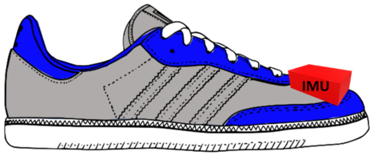
14]. For algorithm tuning across different terrains, an IMU is attached to the foot of the user for greater sensitivity when recording the inertial data. To reduce the impact on the pedestrian’s gait, an IMU was placed above the toes on top of the right shoe, as shown in
Figure 3, thus providing the most consistent step and ZVI detection [
23,
24]. Attaching the IMU on the foot in other locations, such as the ankle or the heel requires additional structural support and limits the motion and affecting the natural gait.
Data were collected using a six degree of freedom (DOF) IMU from Inertial Elements [
25]. Inertial Elements’ IMU is low-cost and compact; the sensor specifications are in
Table 1. IMU data are recorded via Bluetooth to an Android app, OsmiumScope. The IMU is attached using Velcro above the toe of the shoe to reduce the impact on the natural gait. By attaching the IMU with Velcro, there are no straps under the arch of the foot to alter each footstep or any casing at the heel that affects the balance of the user and changes the gait. The adhesive Velcro strips cover the base of the IMU housing; the larger contact area reduces the likelihood of the IMU shifting during data collection and affecting the measurements. The IMU records data along three orthogonal axes, X, Y and Z, for both accelerometers and gyroscopes. The collected data on the mobile phone were exported for processing.
Tuning data were collected on four terrains using an IMU attached to athletic trainers. A single user wearing athletic trainers was used for data collection, thus eliminating gait variation. The test locations were all in England. Tuning data for the concrete and grass terrains were collected at Royal Air Force Mildenhall (RAFM) on a concrete running track and grass field. Data used for tuning the pebble terrain were collected at Chesil Beach. The sand tuning data were collected at Weymouth Beach. The beach terrains are defined using the Wentworth scale [
26], based on the grain size. Chesil Beach is a pebble beach with aggregates of 30–200 mm in diameter, and Weymouth Beach has very fine to fine sand with grains of 0.0625 to 0.25 mm in diameter. Each beach and their respective grain types are shown in
Figure 4.
Tuning for the algorithm was performed by manually identifying the ZVIs and zero angular rate intervals across the terrains. Initial analysis indicated that the less firm the terrain was, the more variation in the threshold value.
Figure 5 shows data from the test statistic accelerometer magnitude of the four terrains. The ZVIs are noisier for the sand and pebble terrains, whereas the concrete and grass terrains are more stable.
The values for each parameter were determined from manual tuning and data selection. A visual inspection of each stance phase was conducted by selecting the start of the ZVI following the heel strike. A second point was selected at the end of the ZVI before the magnitude increases due to the toe release. All magnitude and time data between the two points were exported, saved for each footstep from the tuning data and averaged to create a threshold value. The time between the first and second selected points is saved, and the difference is calculated for the ZVI duration. The difference is saved for each set of selected points and averaged for the tuning data for the ZVI duration of the tested terrain. An additional difference is calculated between the second point selected and the following first point of the next ZVI. This difference is saved for the tuning data and averaged for the duration of the walking cycle, excluding the ZVI. Finally, the process is repeated for the gyroscope magnitude data to determine the zero angular rate threshold. The average values of the four parameters of the terrains is shown in
Table 2. The four parameters comprise the tuning for the algorithm used for pedestrian navigation.
One standard deviation is then applied to each calculated average for the parameter threshold values to account for missed step detections in the walking cycle. The standard deviation for each parameter is shown in
Table 3. The missed detections are attributed to variations in the ground, especially for softer terrains, where the ground gives way under each footstep. The final threshold values for each parameter are in
Table 4. The threshold value for the zero velocity threshold for concrete of 1.42 ± 0.21 m/s
2 is within the standard deviation of the 1.239 m/s
2 single indoor threshold accepted value from the literature.
The ZVU is performed whenever the test statistic is below the threshold. The algorithm waits for the ZVI and duration of the walking cycle before searching again for a value below the threshold. The ZVI and walking cycle vary for each terrain, so the wait time is terrain-dependent. This process is repeated for the ZARU. The magnitude thresholds for the accelerometers and gyroscopes are synched, and the ZARU is identified when the test statistic is below the threshold of the gyroscope magnitude. If a ZVI and zero angular rate instance occur within one ZVI duration, the heading and position are updated.
The differences in the measured threshold values are consistent with the sensory awareness that different terrains affect the natural gait; thus, separate threshold values need to be considered when using a ZVU algorithm.
When testing the algorithm, new data were collected across the four terrains. The threshold value used in the literature of 1.239 m/s
2 is derived from Schwartz’s work on walking patterns of “normal” males [
12], as well as Gast’s work on walking speed on different terrains [
11]. OpenShoe assumes the walking surface to be firm, without uneven imperfections. These assumptions are similar to concrete and thus accepted as a suitable comparison for the concrete terrain, as the majority of work in ZVU-aided inertial navigation focuses on indoor navigation. The other terrains considered are not always on a firm foundation, meaning the ground on which the user walks can give way under each footstep. Additionally, the surfaces of the three other terrains may exhibit unevenness or imperfections.
To test the algorithm, datasets were collected at four locations: RAFM– concrete; Red Lodge Community Hall—grass; Aldeburgh Beach—pebbles; and Southwold Beach—sand.
Figure 6 is a picture of each terrain at the test locations.
To compare the calculated terrain thresholds against existing ZVU algorithms, the opensource OpenShoe ZVU algorithm was used as a baseline. For an accurate comparison, a 100 m straight line was measured with surveying tape. A single user collected data along the straight line to eliminate heading errors. Data were collected at 125 Hz with the Inertial Elements IMU for five tests at each location. The collected data were post-processed and analyzed with the OpenShoe algorithm using existing threshold values and compared to the OpenShoe algorithm using terrain-specific parameters. The 100 m is a truth reference distance, against which the default ZVU-aided inertial navigation algorithm is compared. Additionally, the ZVU-aided inertial navigation algorithm with terrain-dependent parameters was compared to the 100 m reference. Comparing both ZVU algorithms to the 100 m reference distance shows how each algorithm performs in calculating the distance traveled.
3. Results
The ZVU algorithm identifies the first instance under the threshold value in the ZVI and waits the time interval before searching for another instance. Occasionally, steps are missed due to time constraints or the magnitude never crossing below the threshold.
Figure 7 highlights steps using the ZVU algorithm on pebble terrain.
Figure 7a uses single threshold values not tuned to the terrain—missing five steps.
Figure 7b uses terrain-specific threshold values and identifies all nine steps.
The baseline ZVU algorithm was run for all terrains using the single indoor threshold value across each test and terrain. The ZVU algorithm was then run for all terrains with terrain-specific parameter values. The distances measured using ZVU-aided inertial navigation from each test are compared to each other and the 100 m reference. A comparison between the terrain-specific thresholds and the indoor single threshold is calculated using the root mean square error (RMSE) from the measured distances in Equation (2):
where
f is the measured distance of each test, and
o is the 100 m reference. The RMSE comparisons between the terrain-specific parameters and single threshold are in
Table 5. Using the single threshold for concrete results in a 4.601 m error. This is the most accurate result for the single threshold and consistent with concrete terrain using terrain-dependent parameters. Concrete is a hard surface similar to the indoor surfaces on which the single threshold was tuned. For the other terrains, the single threshold yields distance errors of 29.351, 35.137 and 36.253 m. Using terrain-dependent thresholds yields an RMSE below 8.239 m for all terrains. The improved accuracy in the distance measured using terrain-dependent thresholds versus an indoor threshold is in
Table 5 and calculated in Equation (3):
where
RMSEt is the RMSE value for each terrain-dependent threshold,
RMSEi is the RMSE value using the indoor threshold, and 100 is the reference distance.
Using the single indoor threshold parameters, a distance of 95.399 m was calculated for the concrete terrain, and it performed worse for each subsequent terrain. The terrain-dependent parameters are tuned to the specific terrains. The terrain data were tested using the parameters for the other terrains; for example, the pebble data were tested using concrete parameters. This was repeated for every permutation of terrain and terrain parameters.
Table 6 shows the distances when terrain data are tested using parameters for other terrains. The ZVU algorithm using the pebble and sand terrain parameters is more likely to identify steps because the threshold is larger, but when the sand and pebble data are tested using the concrete or grass parameters, the RMSE calculated is above 18.355 m.
4. Conclusions
In this work, fine-tuning a ZVU-aided inertial navigation algorithm with terrain-specific threshold parameters demonstrated that terrain-dependent tuning affects the navigation solution. Using terrain-specific threshold values of four parameters (accelerometer and gyroscope magnitudes and durations of the ZVI and walking cycle), instead of values optimized for indoor use on hard surfaces, improved navigation accuracy. The terrain-dependent thresholds improved the distance measured by 3.157, 27.531, 29.316 and 31.036% across concrete, grass, pebble and sand terrains. The accuracy was better on concrete and grass because as pedestrians walk on sand or pebble terrains the terrain gives way, causing more variation in accelerometer and gyroscope magnitude during each step.
Future investigation is needed to determine if reducing the number of terrain classes to two, hard and soft, can improve accuracy and reduce the computational load of ZVU algorithms. Further investigation is recommended to understand the algorithm in real time as the pedestrian transitions between terrains. Additionally, the fine-tuning of the algorithm needs to account for navigation solutions due to heading changes. This will also incorporate tuning further parameters of the ZVU algorithm to include measurement noise, use with filtering algorithms and multiple ZVU updates within a single ZVI.


