1. Introduction
With the increased use of Unmanned Aircraft Systems (UASs) for a wide variety of applications, such as law enforcement, search and rescue, agriculture, infrastructure inspection, maintenance, mapping, and journalism, it is expected that UASs will be taking off, landing, or otherwise operating at airfields at the same time as manned aircraft. These operations may lead to a smaller separation between participants and, thus, a higher collision risk. In manned aviation, the standard separation minima of 5 nautical miles horizontally and 1000 feet vertically between aircraft are used worldwide. The resulting cylinder forms a protection zone, which serves as a protective layer around the aircraft. If the protection zones of two aircraft overlap, this is generally referred to as a loss of separation.
However, the dimensions of such protection zones cannot be transferred to unmanned aviation without adjustments, as these distances are simply too large for small UAVs. At the same time, these large separations cannot be applied effectively in the usage applications of drones, for example, in urban areas. Therefore, RTCA SC 228 DO-365 defines significantly smaller protection zones for unmanned aviation. Here, the horizontal separation is set to 4000 feet and the vertical distance of each aircraft to each other to 450 feet [
1].
To enable smaller separation, relative position and velocity estimators are required that can meet stricter navigation performance. Typically, ADS-B transmits traffic position and velocity estimates output by the onboard GNSS receiver. In [
2], Farrell et al. discussed the benefits of using raw GNSS measurements instead of position and velocity information based on coordinates. A measurement-based ADS-B implementation, which transmits raw measurements from the GNSS receiver rather than aircraft state vectors and performance parameters, has additionally been proposed in previous papers by the authors to improve surveillance performance and add integrity to the surveillance solution. The test results of the proposed method have shown meter-level relative position accuracy and millimeter-per-second-level relative velocity accuracy [
3].
This paper will review these methods and their performance, propose an implementation for ADS-L, and discuss how this level of performance can enable the simultaneous operation of manned and unmanned aircraft at low altitudes in the vicinity of airfields. This paper will furthermore discuss recent flight tests with one manned aircraft and two UASs and illustrate the benefits of using GNSS measurement-based ADS-L data for separation assurance as opposed to traditional methods.
2. Background
2.1. Relative Navigation and Raw Measurements
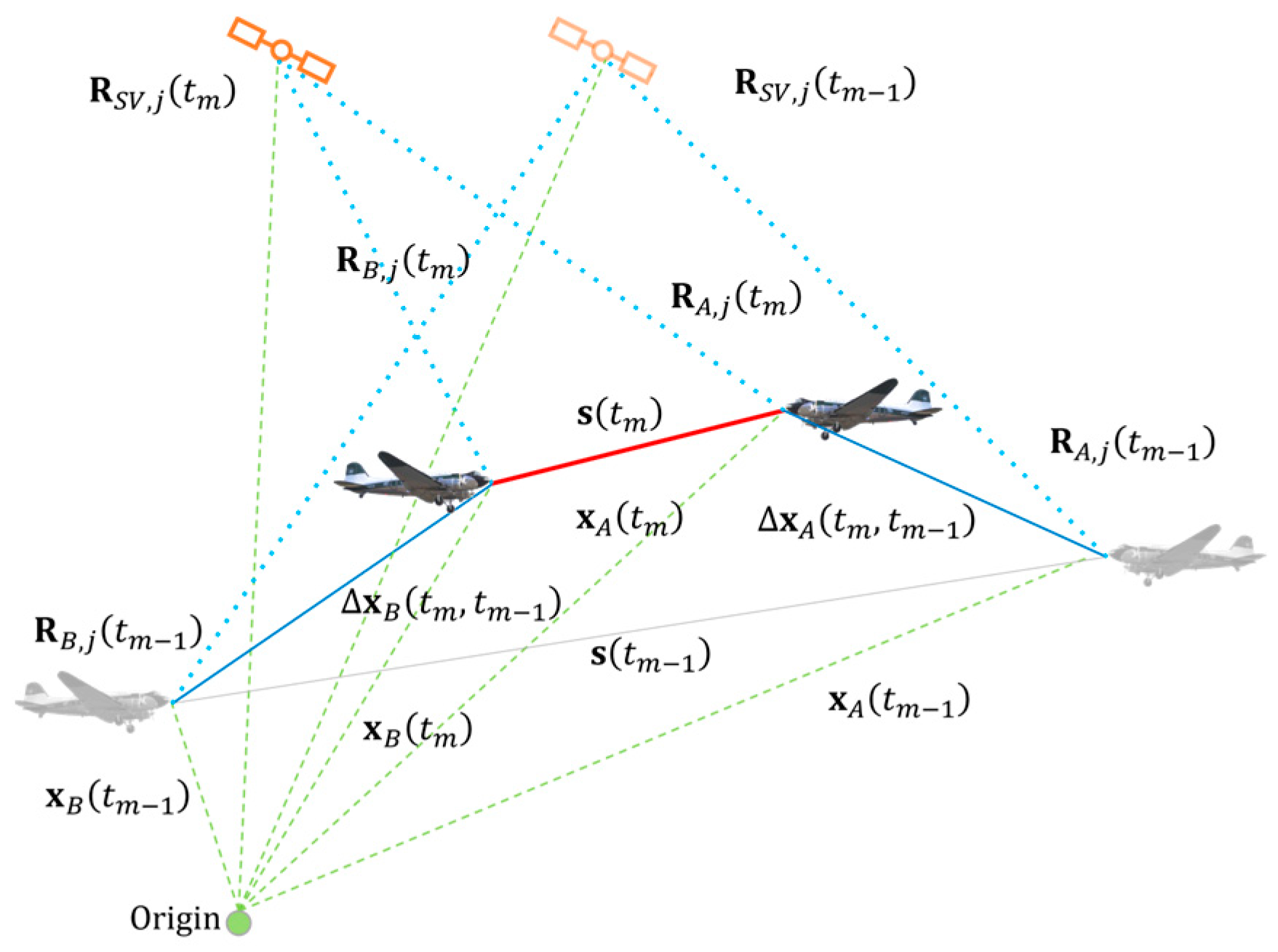
The geometric principle of relative navigation is illustrated in
Figure 1. Two consecutive periods of time are considered in which the position of the satellite and the distances of two aircraft to the satellite are calculated. The relative position vectors of the aircraft and the separation vector to each other are determined from these position changes over time. Also, the aircraft’s relative speed to each other can be calculated by deriving the relative position over time. The distances are substituted in this process by the pseudorange PR and the carrier-phase ADR to make use of raw measurements.
This method effects a reduction in measurement errors. The clock error is eliminated by using the same satellite identification (SVID), as both aircraft receive the same clock errors due to the runtime of the identical satellites. These errors will be canceled when the measurements of the two aircraft are compared. In addition, spatially related errors are reduced to a minimum, as the conflict scenarios between two aircraft take place in a locally nearby area. As a result, other errors such as tropospheric or ionospheric delays can be significantly reduced. This has already been proven in several publications, including by the authors of [
3].
2.2. Automatic Dependent Surveillance–Light (ADS-L)
With the new entrance of UASs into the current airspace, the risk of midair collisions increases. This also includes higher collision risks between unmanned and manned aviation if they are operating in the same airspace. iConspicuity, also defined as “in-flight capability’ to transmit position and/or to receive, process and display information about other aircraft, airspace, weather, or support to navigation in a real time with the objective to enhance pilots’ situational awareness” [
4], could be key to improving safety. According to a survey conducted by the EASA in 2023, the main barrier for general aviation (GA) pilots to obtaining anti-collision systems are the high costs of these devices and their incompatibility with other systems [
4]. This survey confirms the need for a common, open-source system to provide an iConspicuity solution for a U-space due to the limited availability of suitable systems. This system is planned to be operatable on mobile phones in the future to enable a low-cost and accessible solution [
4]. To make all aircraft become electronically conspicuous to U-space Service Providers (USSPs), the EASA published the “Technical Specification for ADS-L transmissions using SRD-860 frequency band (ADS-L 4 SRD-860)”, providing details on the transmission protocol called ADS-L.
The ADS-L message is based on the need for electronic conspicuity fixed in the SERA.6005(c). The technical specification provided by the EASA [
5] aims to comprehensively outline its physical layer, timing intricacies, data semantics, and byte packaging, excluding user interface, configuration, and other practical system aspects. It is open for implementation by any interested party and includes C code snippets for illustrative purposes [
5]. Implementing the ADS-L protocol involves critical components: a GNSS receiver for accurate 3D localization and timing, a host processor for eID protocol processing, and an RF frontend for RF signal transmission [
5]. Several methods are used to detect and reduce errors during transmission. Manchester encoding ensures reliable data transmission by converting bits into specific signal transitions, facilitating synchronization between the sender and receiver [
5]. CRC encoding is utilized for error detection, providing a mechanism for verifying data integrity and enhancing transmission reliability [
5].
3. Methodology
This section presents the math behind the calculation of the relative position and velocity estimation. Additionally, a conflict detection method based on the TCAS logic is discussed.
3.1. Relative Position and Velocity Estimation
The math of this method was already described in detail by the authors of [
3].
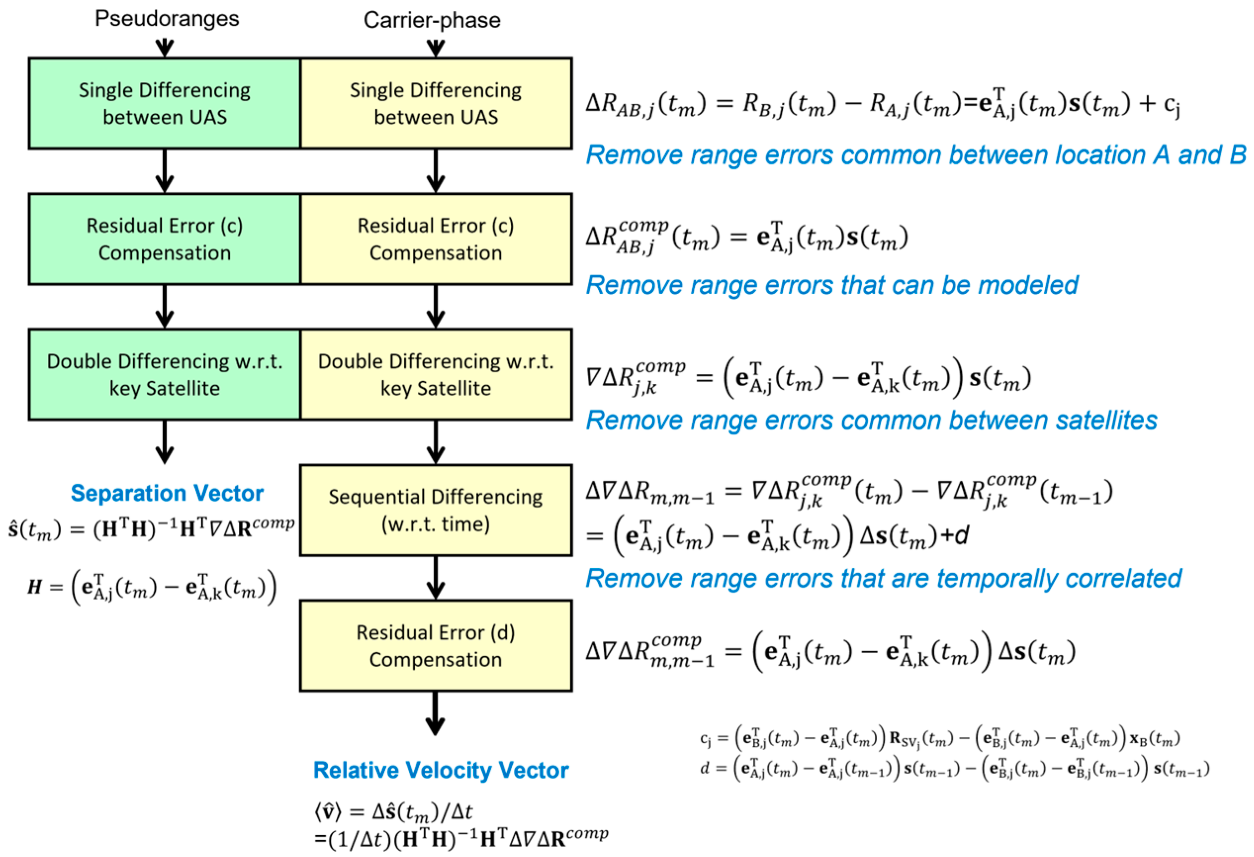
Figure 2 summarizes the estimation of the relative position as a separation vector
for each time epoch
tm based on the pseudorange measurements (1) and the relative velocity vector
as a change in the separation vector
over
based on carrier-phase measurements (2).
The relative position estimation is based on the pseudorange measurements from Aircraft
A and
B to all matching satellites for two consecutive epochs, as shown in
Figure 1.
For each time epoch, the separation geometry and vectors from the aircraft and each satellite will be determined as a single difference range measurement, resulting in the relative position vector
s = xA − xB, also called a separation vector. After subtracting the geometry compensation term
cj, inducing satellite
j, and forming the compensated single difference
, this will then be subtracted for all satellites from the compensation of a key satellite
k, typically determined as the one that has the highest elevation in the current constellation. Thereby, the double difference ranges
can be formed, where errors between satellites (e.g., receiver clock errors) will be canceled, and spatial correlated errors will be reduced significantly [
3]. The relative position vector
can now be estimated using a least square solution characterized by (1).
The relative velocity estimation, using the carrier-phase measurements now, extends the previous described calculation by a triple difference, subtracting the double difference result from time epoch
tm from the double difference result of a previous time epoch
tm−1 to compensate for the satellite movement and the separation vector change during the time interval as characterized by (2).
Both estimations are the most accurate if R, as the relative vector between an aircraft and a satellite, is substituted in (1) by the pseudorange measurements PR for the relative position estimation and in (2) as derived by the carrier-phase measurements ADR for the relative velocity estimation.
To use the method described above, the GNSS receiver data need to be set up to match the requirements. For the relative position calculations, only data sets with the same time epochs between the own vehicle and traffic may be used. To correct temporarily and spatially correlated errors in the pseudorange and carrier-phase error, only measurements from satellites which were received by both vehicles are used. Measurements received by only one participant are excluded from relative position and velocity calculation.
3.2. Separation Assurance
The relative position and relative velocity, determined based on GNSS measurements, are used to estimate the separation between the own aircraft (referred to as ownship) and another vehicle (from now on defined as traffic) in the future. This concept is inspired by the commonly known traffic alert and collision avoidance system (TCAS), which relies on aircraft equipped with a transponder to identify potentially conflicting aircraft. However, using raw GNSS measurements instead makes it suitable for use on all kinds of aerial vehicles as no heavy and expansive transponder is required. The logic used by TCAS, described in [
6], is adapted and explained in the following section. As the two UAVs were operating at fixed heights during the tests, only the horizontal components of position and velocity are considered.
First, a relative coordinate system with the origin at the position of the ownship is defined. It is used as reference to show the relative position s and velocity
v (2 × 2 vectors), which is given based on the method described in
Section 3.1. All calculations assume a constant relative velocity and do not consider accelerations or other external influences which may change the track or velocity of one or both vehicles. At any time
t, the relative position between the ownship and traffic is given by the following:
Following this, all variables used without the index
t are referred to as the value at
t = 0. Using the Euclidean distance formula, the relative position at time
t can also be expressed as scalar range
r:
Both expressions are used to calculate the required separation information. Given a lookahead time interval [
B,
T], the time of the closest horizontal approach
is the minimum time that satisfies the following condition [
7]:
This expression is equal to the assumption that at
, the horizontal distance
s is minimal; thus,
can be taken as a reference to evaluate the time taken before a possible threat is encountered. Solving the equation can be conducted by calculating the minima of the range, which is given by
:
Additionally, after calculating
, (3) can be rearranged to calculate the horizontal miss distance (HMD):
The TCAS II Resolution Advisory Logic [
6] is based on the math described above; however, it uses the concept of
to estimate the time before reaching the closest point of approach.
is in general defined as the quotient of range
r and the negative of the range rate
(also referred to as the closure rate). Using the range at time zero and the derivate of the range rate (6),
can be calculated as the following:
is only equal to if the ownship and traffic are on a direct collision course and not accelerating. This is especially not the case for operations of UAVs with fast position changes; however, the TCAS logic is still used as a reference and will be used to postprocess the following flight test data. The distance modification, DMOD, which is required to account for edge cases like small closure rates, is not applied in the following method as no thresholds are set for the tests.
4. Flight Test Setup
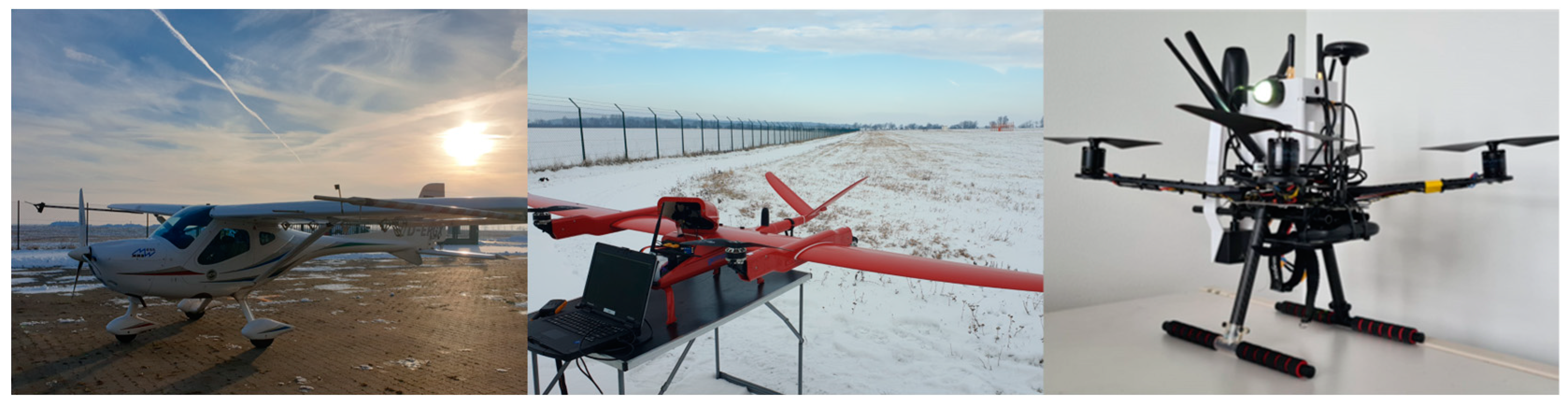
The flight test was conducted as part of the department’s project Safefly at the DLR National Experimental Test Center for Unmanned Aircraft Systems in Cochstedt, Germany. The objective of the flight test was to simulate mixed air traffic in the vicinity of an airfield. One manned aircraft and two UASs were used for this purpose (see
Figure 3).
Due to the strict safety regulations for drone operations at airfields in Germany, only one mission was designed and approved, which was repeated several times. The planned flight corridors can be seen in
Figure 4, with the airfield centered in the middle of the figure. The rectangle frame shows the traffic pattern flown by the Remos GX, with a west outbound takeoff on Runway 25. The racetrack pattern on the lower left shows the path of the fixed-wing UAV Songbird. During the Remos GX’s landing phase, the Songbird was flying with holding patterns directed south of the runway to maintain separation in the case of a missed approach by the aircraft. The Holybro S500 quadcopter was simulating delivery missions near the airfield demonstrated by the dots inside the traffic pattern.
All vehicles were equipped with a self-developed sensorbox, including a GNSS receiver (Remos GX: Septentrio mosaic-X5 mounted on the glareshield; UAS: u-blox ZED-F9P), an ADS-B or FLARM device (Remos GX: TM350 FLARM; UAS: aerobits TR-1F ADS-B In-&Out and FLARM), a LiDAR Benewake TF-03, an LTE module (Sixfab LTE Base HAT), and a computing module (Raspberry Pi 4). All gathered data were transmitted via LTE to all flying participants, to the monitoring crew at the ground station, and to JETVISION servers for traffic information. Additionally, all available data were stored for later evaluation. For this research, flight data, including positions, velocities, GPS pseudorange, and carrier-phase measurements, are of relevance.
5. Flight Test Results
The following results are part of a postprocessing data analysis. In principle, the aircraft was regarded as the reference object and is referred to as own. The two UASs are subsequently referred to as traffic in the evaluation of the results.
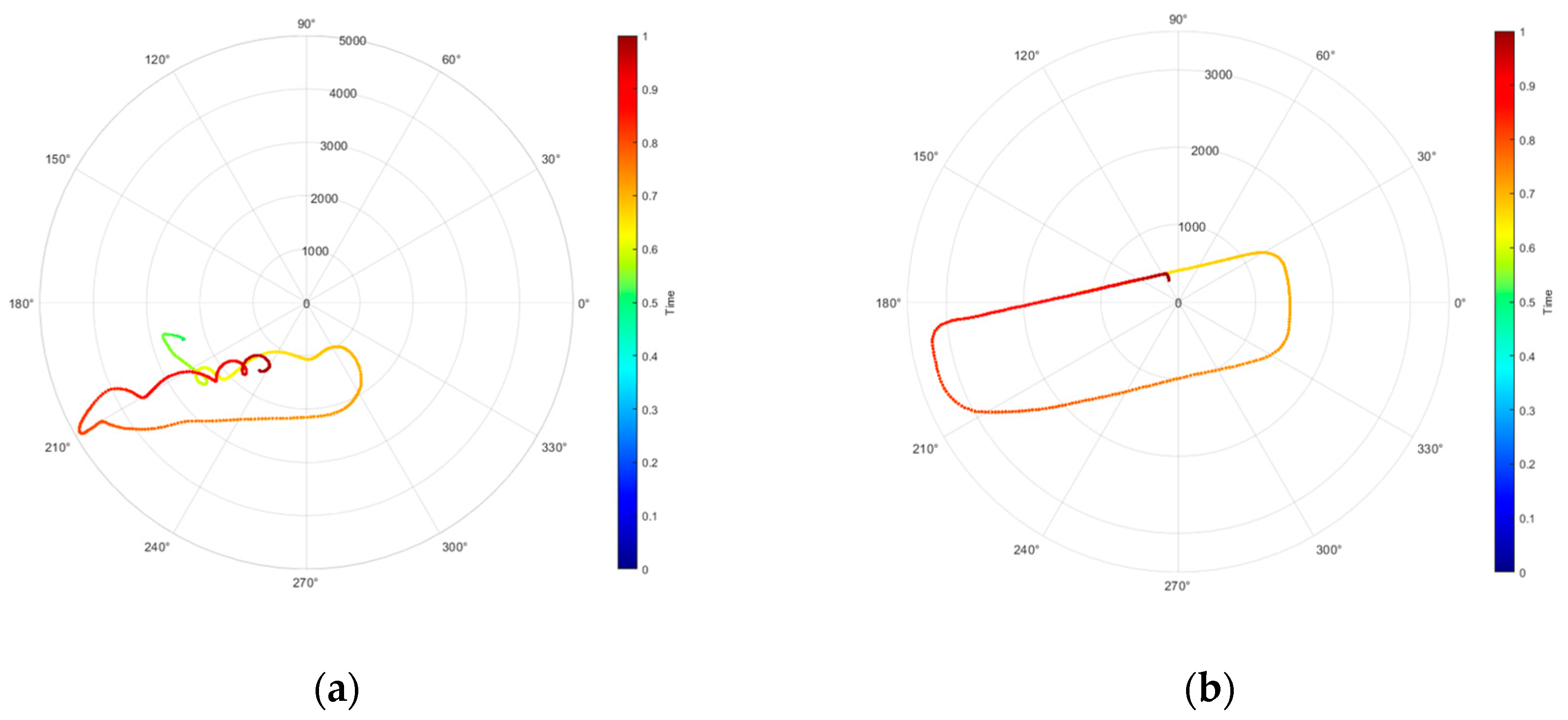
Figure 5 shows the relative position as a distance vector between the Remos GX and the respective UAV as traffic. The Remos GX represents the reference point, and the traffic is indicated over time in relative bearing. In
Figure 5b, the traffic pattern of the Remos GX is clearly visible, as the S500 quadcopter only covered a small distance parallel to the runway. The pattern in
Figure 5a results from the Songbird’s holding pattern, which must be considered relative to the aircraft’s flight path.
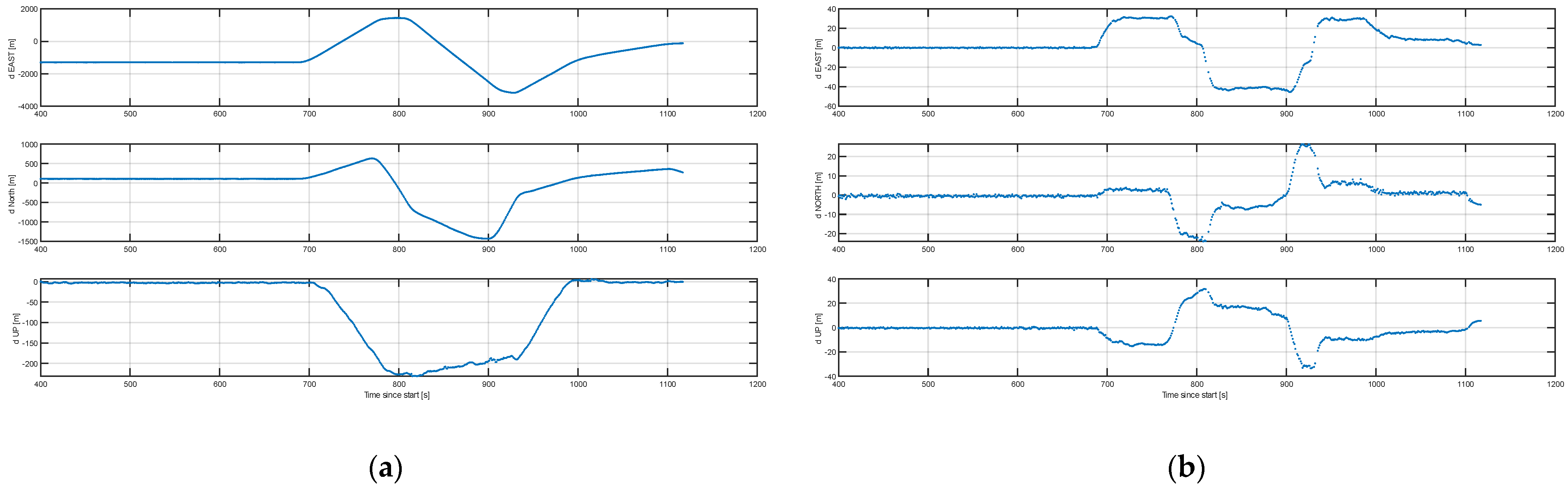
Figure 6 shows the relative position and the relative velocity between the aircraft and the S500 quadcopter transferred to ENU.
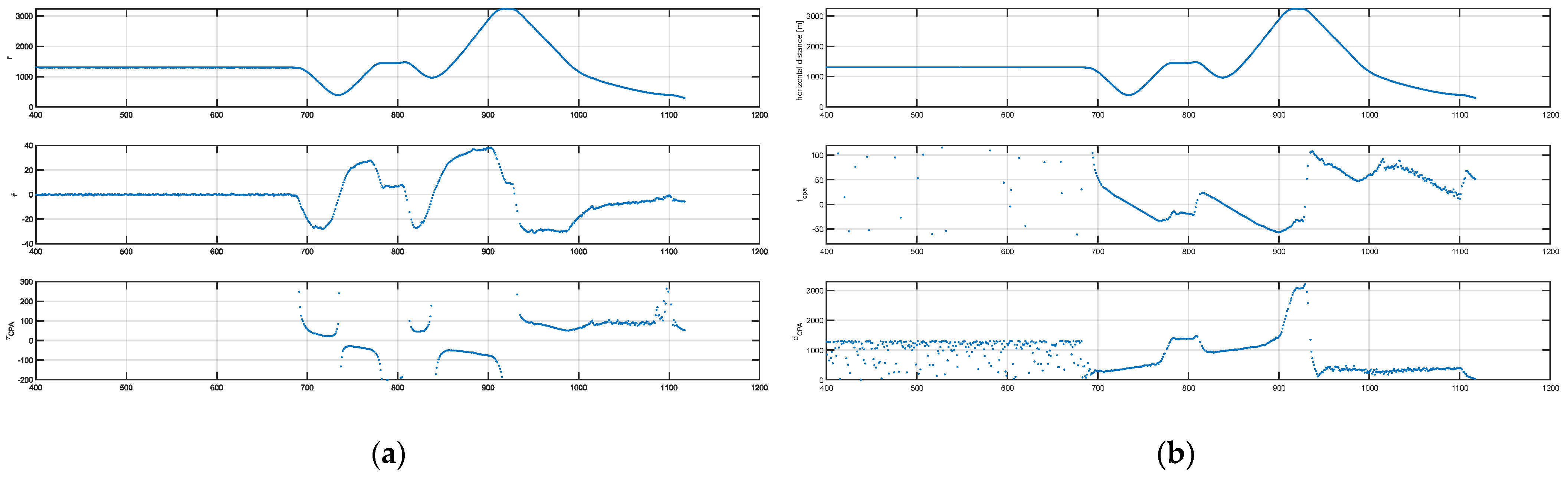
Figure 7 shows the separation calculation with the TCAS logic and with the minimum distance method. The results illustrated in
Figure 6 and
Figure 7 belong to the same mission, where the actual flight began approximately 600 s after the start of the data recording process.
6. Discussion
Despite the beneficial utilization of less than four available satellites mentioned by Farrell in [
8], an open point of contradiction remains. Even with a satisfying number of satellites, sometimes, individual satellites cannot be used. As mentioned at the beginning of this paper, both the ownship and the intruder must have matching satellites for the calculation. As a result, individual satellite data may become useless if only one of the vehicles receives information from a specific satellite.
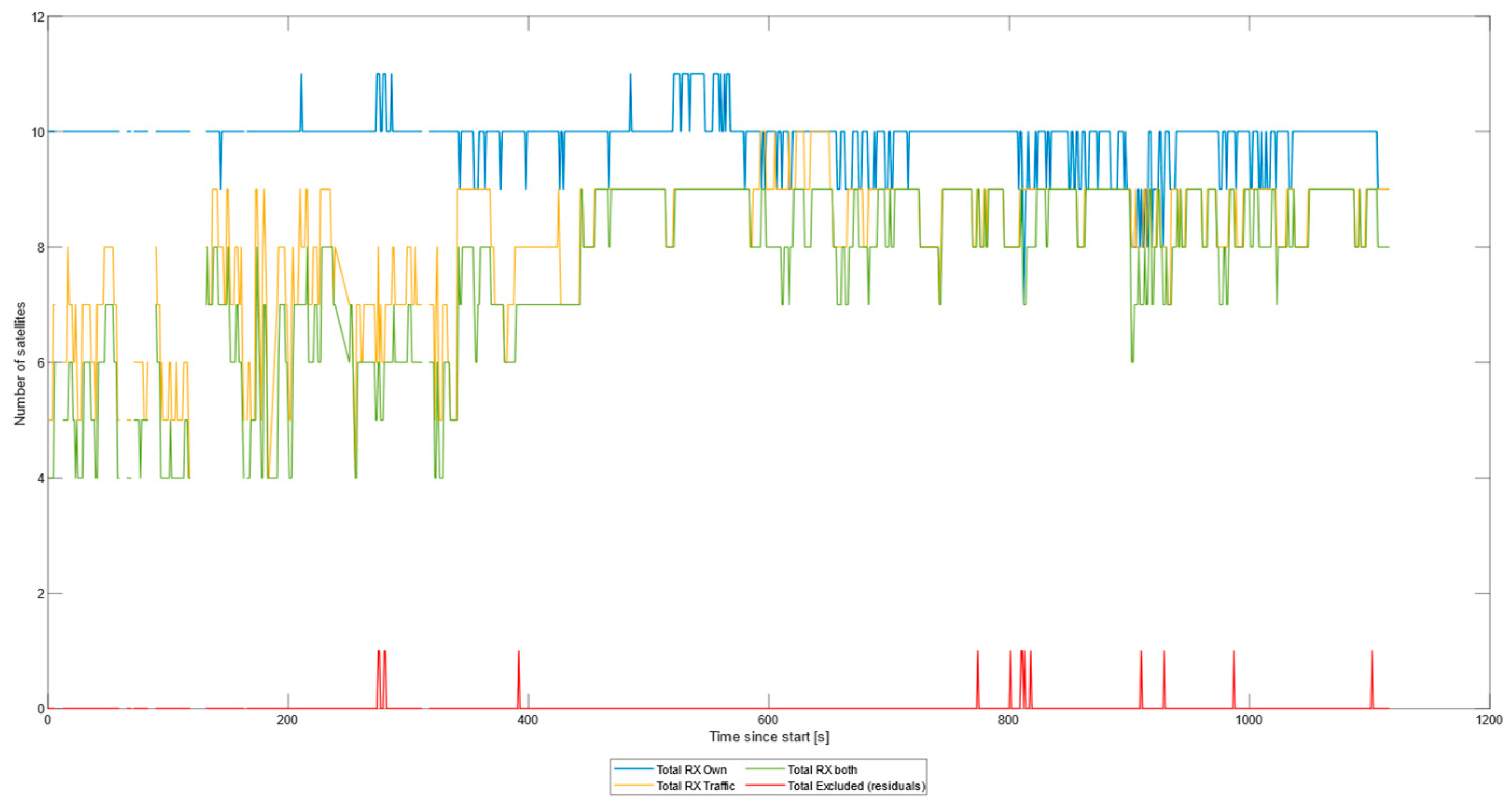
Figure 8 shows this gap by comparing the satellites received by the Remos GX and the Songbird VTOL. Especially in the first third of the flight recording, the number of satellites received by the VTOL (yellow line) varied, and the number of matching satellites (green line) was at certain times only four. However, as the actual flight mission did not start until 400 s after the beginning of the recording (see Results), the minimum number of matching satellites during the flight was at least six and, in the best case, nine.
Additionally, information on the maximum number of satellites received per time epoch per vehicle can be taken from
Figure 8. The Remos GX received measurements from up to 11 satellites during the flight. From these data, conclusions can be drawn about the requirements for the ADS-L messages.
Transmitting the raw measurement via ADS-L, the payload of each message needs to contain the time of the epoch and for each satellite the information of the identification (SVID), the pseudorange measurement (PR), and the carrier-phase measurement (ADR). The time equals 32 bits, the SVID equals 8 bits, and the PR and ADR each equal 32 bits. For each time epoch, the payload container of the ADS-L message always equals 8 bits for the time and 72 bits per satellite measurements multiplied by the number of satellites N:
As shown in
Figure 8, at the maximum, 11 satellites were received, which requires a payload length of 824 bits. In their technical specification, the EASA explains that the payload length of an ADS-L message is variable and can be adjustable, but it must be a multiple of 32 bits [
5]. The structure specified in (10) is not consistent with the EASA requirements. This issue needs to be addressed in further research.
7. Conclusions
This paper presents the flight test results of estimating the relative positions between two aerial vehicles based on GNSS raw measurements. The evaluation of raw data to achieve a measurement-based solution shows their clear usability for evaluating the separation between two aerial vehicles. As an extension, a reliable closure rate is established for the distance vector to reproduce collision detection in the manner of manned aviation TCAS.
Furthermore, this paper provides insights into the new ADS-L transmission protocol and the necessary requirements for a measurement-based separation assurance approach. Future work will include the possible compressing of the present data to fulfill the objective of transmitting at least the own GNSS raw measurements to other parties in the sky or on the ground. Additionally, more flight tests are required to provide a sufficient validation of the ADS-L real-time implementation with assessments of the message update and loss rate as well as the capability of ADS-L transmission to enable conflict detection and moreover conflict resolution.
Author Contributions
Methodology, B.L. and M.U.d.H.; software, A.-S.P. and M.U.d.H.; validation, B.L. and V.K.; formal analysis, V.K.; data curation, M.U.d.H.; writing and visualization, B.L.; supervision, M.U.d.H. All authors have read and agreed to the published version of the manuscript.
Funding
This research received no external funding.
Institutional Review Board Statement
Not applicable.
Informed Consent Statement
Not applicable.
Data Availability Statement
Data are contained within the article.
Conflicts of Interest
The authors declare no conflicts of interest.
References
- RTCA Special Committee 228. DO-365: Minimum Operational Performance Standards (MOPS) for Detect and Avoid (DAA) Systems; RTCA Inc.: Washington, DC, USA, 2017. [Google Scholar]
- Farrell, J.L.; McConkey, E.D.; Stephens, C.G. Send Measurements, Not Coordinates. NAVIGATION J. Inst. Navig. 1999, 46, 203–215. [Google Scholar] [CrossRef]
- Duan, P.; Uijt De Haag, M.; Farrell, J.L. Flight Test Results of a Measurement-Based ADS-B System for Separation Assurance. NAVIGATION J. Inst. Navig. 2013, 60, 221–234. [Google Scholar] [CrossRef]
- Foltin, V. iConspicuity & ADS-L. In Proceedings of the EASA—CASIA Meeting, Cologne, Germany, 9 May 2023. [Google Scholar]
- EASA. Technical Specification for ADS-L Transmissions Using SRD-860 Frequency Band; ED Decision 2022/024/R, Issue 1; EASA: Cologne, Germany, 2022.
- Munoz, C.; Narkawicz, A.; Chamberlain, J. A TCAS-II Resolution Advisory Detection Algorithm. In Proceedings of the AIAA Guidance, Navigation, and Control Conference, Boston, MA, USA, 19–22 August 2013. [Google Scholar] [CrossRef]
- Munoz, C.; Narkawicz, A. Time of Closest Approach in Three-Dimensional Airspace; NASA/TM 2010-216857; NASA: Washington, DC, USA, 2010.
- Farrell, J.L. Enabling Collision Avoidance with Raw Position Measurements and Updated ADS-B Software. InsideGNSS, 28 July 2017; 46–52. [Google Scholar]
| Disclaimer/Publisher’s Note: The statements, opinions and data contained in all publications are solely those of the individual author(s) and contributor(s) and not of MDPI and/or the editor(s). MDPI and/or the editor(s) disclaim responsibility for any injury to people or property resulting from any ideas, methods, instructions or products referred to in the content. |
© 2025 by the authors. Licensee MDPI, Basel, Switzerland. This article is an open access article distributed under the terms and conditions of the Creative Commons Attribution (CC BY) license (https://creativecommons.org/licenses/by/4.0/).

