Abstract
This research presents the main results related to the lightweighting of a specific scissor lift platform with the following key specifications: a working load limit of 3000 N and a platform height of 5.5 m. The design (for both steel and innovative materials) was conducted by evaluating the load conditions, some of which were derived from relevant standards. The new solution, which uses aluminum and composite materials instead of structural steel, reduces the overall weight from approximately 24.7 kN to 13.1 kN (a 53.1% reduction). Additionally, the lifting and travel power required for the new design is about half that of the original solution.
1. Introduction
Nowadays, issues related to energy efficiency and sustainability are among the most important topics that many different research groups focus on and economic policies base their activities on.
In general, to increase energy efficiency, especially in machines, it is possible to operate in two ways. The first approach involves increasing motor efficiency, particularly using fluids or electric power, which helps to reduce pollution, at least where the vehicle is used. This aspect has been extensively studied, especially regarding vehicles.
The second methodology to increase energy efficiency is to reduce the weight of machine components using specific materials [1,2,3]. Implementing this strategy, it is possible to use lighter components compared to the original ones. This can lead, for example, to improved performance, such as increased speed (with the same power installed on the vehicle), or, by maintaining constant performance, reducing the power (whether internal combustion or electric) installed on the machine.
Some studies have been carried out both on vehicle components and industrial vehicles [4] or earth-moving machines and cranes [5]. This research falls within this field. The main objective was to design a scissor lifting platform using traditional construction steel and develop a new solution involving innovative materials for this sector, such as aluminum alloys and composite materials, primarily to reduce the dead weight of the machine.
2. Specifications for the Scissor Platform Lifter and Design in the Original Configuration
The main parameters for the scissor lifter design are as follows: a maximum working load limit of 3000 N; a working platform height of 5.5 m; and a platform length of 2500 mm. The number of cycles is 320,000, and the load spectrum factor is one, i.e., the platform is always lifting the maximum load. Figure 1 shows the main dimensions of the machine.
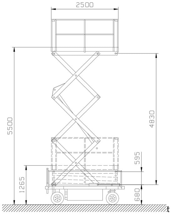
Figure 1.
Main size of the machine [mm].
3. Load Conditions
This machine is subjected to various load conditions due to the load position and external loads (payload, wind, etc.). There are several standards that define these load conditions; the most important ones are as follows: UNI EN 280-1:2022, UNI EN 280-2:2022, UNI- EN 1570:2015, UNI EN 13001-1:2015, and UNI EN 13001-2:2021.
In particular, the machine was subjected to the actions induced by the payload in different positions on the walking floor, with a wind pressure of 100 N/mm2, manual force equal to 400 N (applied above the walking floor (1.1 m)), and the maximum inclination of the floor equal to 1.5°.
Through analytical equations, it is possible to estimate the internal forces on each component of the machine. In particular, Figure 2 shows the main variables adopted. The red point represent the barycenter of the walking surface, the red arrow the position of the operator while x, a and b are the main variables. Figure 3 illustrates the hydraulic cylinder force required to lift the payload, and Figure 4 depicts the internal forces on the DC beam.
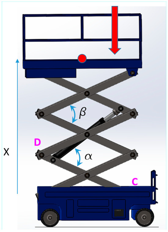
Figure 2.
Platform solid model and main variables.
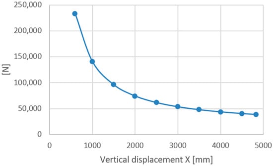
Figure 3.
Hydraulic cylinder force vs. vertical displacement.
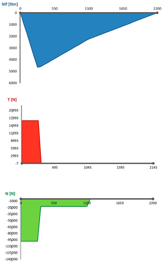
Figure 4.
Axial action of the DC beam at the maximum hydraulic cylinder force.
It can be seen that the maximum action occurs at the lowest position of the platform; the action exerted by the hydraulic cylinder decreases as the height of the platform increases.
Through these internal actions, the scissor lift beams were designed. The material adopted was the classic structural steel S275JR EV 10025-2:2004, the main properties of which are shown in Table 1. Table 2 shows the main properties of the 36 NiCrMo16 Bon. EN 10083-3:2006 steel used for pins.

Table 1.
Main mechanical properties for the S275 JR steel.
Table 2.
Main mechanical properties for the 36 NiCrMo16 bon steel.
The geometry of the beams is a classic tubular structure with dimensions of 150 × 100 × 5 mm. The pin diameter is 65 mm. Figure 5 shows details of the beam and pin.
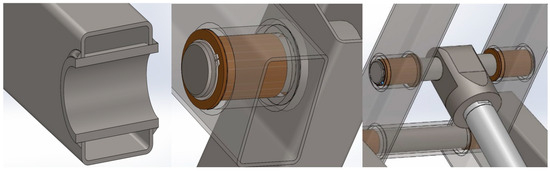
Figure 5.
Beam and pin and their joint.
4. Optimizations
This chapter reports the optimization of the main parts of the scissor lift platform by using innovative materials for these machine types.
4.1. Basket
Figure 6a shows the main dimensions of the basket, designed using S275 JR steel, while Figure 6b presents the displacement results from finite element model analyses on the walking floor, considering the external load (payload) applied at the center of the base.
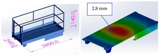
Figure 6.
The basket displacement results from the fem analyses [mm].
The lightweighting process was performed by adopting the aluminum alloy, specifically the EN AW 6061 T6 EN 573.3 aluminum alloy. This material was chosen because it is economical, easily available on the market, and weldable. The main mechanical properties are reported in Table 3.
Table 3.
Main mechanical properties for the EN AW 6061 T6 aluminum alloy.
Due to the lower value of Young’s modulus for this material (about one-third compared to steel), which is closely related to the displacement of the structure, it is necessary to introduce additional beams under the walking floor to increase the stiffness of the floor. Figure 7 illustrates this implementation.
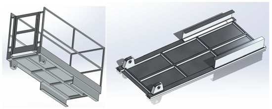
Figure 7.
Solid model of the basket made by aluminum alloy.
The weight of the basket made from steel is 2375 N, while the weight of the new solution made from aluminum alloy is 893 N. The weight reduction is approximately proportional to the ratio of the densities of the two materials, as shown in Equation (1).
4.2. Beam
The weight reduction in the beams was achieved by adopting composite materials [6,7,8]. The properties of the composite fiber and epoxy resin are reported in Table 4, while Table 5 shows the mechanical properties of the laminate, considering a 65% fiber content. The sandwich structure was composed of 40 layers with the following specifications relative to the axis of the beam: −5% (35%, 14 layers); −45% (10%, 4 layers); 90% (10%, 4 layers); 45% (10%, 4 layers); and +5% (35%, 14 layers). The properties of the sandwich are reported in Table 6. The final size of the beam was 150 × 100 × 8 mm. Due to the weight reduction in the basket and the beams, it was possible to lighten the pins as well. Specifically, the final solution for these elements was designed using the same material, as reported in Table 2, maintaining the same external diameter (65 mm) but with an inner hole diameter equal to 50 mm. In this case, in order to avoid galvanic corrosion, it was necessary to decouple the materials. For this reason, a thin sheet of plastic material was inserted between the aluminum sleeve and the composite material beam.
Table 4.
Main mechanical properties for carbon fiber and epoxy resin.
Table 5.
Main mechanical properties for the lamina.
Table 6.
Main mechanical properties for the sandwich.
Figure 8 shows the beam and the joint with the pins fitted with a specific aluminum bushing.
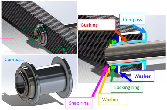
Figure 8.
Beam (composite material), compass (aluminum alloy), and pin (steel alloy).
Figure 9 shows the finite element analysis results for the beam and compares the results between the steel and composite material solution.
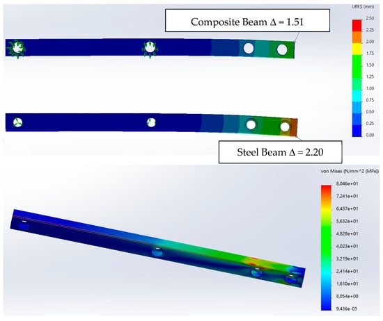
Figure 9.
Numerical results for the beam made by steel and composite material.
5. Results
Table 7 reports the weight of the main part of the platform and its variation with respect to the steel solution, comparing it with the aluminum and composite solutions. This variable was estimated as reported in Equation (2).
Table 7.
Weight of the main element of the platform [N].
It is important to note that the weight reduction also affects the force required to lift the platform, decreasing it from 233,100 N to 149,200 N. This reduction allows for a smaller hydraulic cylinder. Additionally, the weight of the hydraulic cylinder can be further reduced using composite materials.
As reported in [9,10], using composite materials for the hydraulic cylinder can result in a final weight that is 18% of the weight of a steel solution. In this study, the reduction achieved was approximately 20%.
Figure 10 shows hydraulic cylinder performance, specifically the force required to lift the platform and the piston head velocity. Based on these performance metrics, it was possible to estimate the nominal power required to lift the platform. Assuming a mechanical efficiency of 8/10, the power required would be 1780 W, compared to 2700 W for the steel platform.
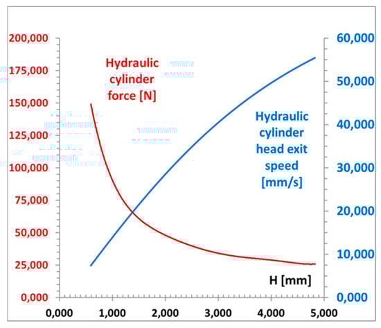
Figure 10.
Hydraulic cylinder performance.
6. Conclusions
This research presents the results regarding the lightweighting of a specific lifting machine, specifically a medium-sized scissor lift platform with a payload of 3000 N and a maximum platform height of 500 mm. After designing the machine, an innovative version was developed using aluminum alloy and composite materials to reduce its weight. The new solution demonstrated that it is possible to achieve a platform with the same performance but with approximately half the weight and power requirements for lifting and movement compared to the original design.
Given the good results, research should continue, focusing on two main areas. The first is to evaluate the actual load conditions (measured in the field), study the environmental effects (for which protective sheets are used on the composite beams), conduct experimental tests, and assess economic feasibility. The second area should extend this research to other machines, particularly lifting equipment.
Funding
This research was funded by the European Union—NextGenerationEU (National Sustainable Mobility Center CN00000023, Italian Ministry of University and Research Decree n. 1033—17 June 2022, Spoke 11—Innovative Materials & Lightweighting). The opinions expressed are those of the authors only and should not be considered as representative of the European Union or the European Commission’s official position. Neither the European Union nor the European Commission can be held responsible for them.
Institutional Review Board Statement
Not applicable.
Informed Consent Statement
Not applicable.
Data Availability Statement
Data is contained within the article.
Acknowledgments
The author would like to sincerely thank the engineer Alessandro Paccini for his indispensable contribution to the development of this research.
Conflicts of Interest
The author declares no conflicts of interest.
References
- Omar, F.; Jimi, T.; Mohini, S. Lightweight and Sustainable Materials for Automotive Applications; CRC Press: Boca Raton, FL, USA, 2017; ISBN 9781315152967. [Google Scholar]
- Van Acker, K.; Verpoest, I.; De Moor, J.; Duflou, J.R.; Dewulf, W. Lightweight materials for the automotive: Environmental impact analysis of the use of composites. Rev. De Métallurgie 2009, 106, 541–546. [Google Scholar] [CrossRef]
- Md Abdul, M.; Mohd Sapuan, S. Materials Selection and Design; Springer: Singapore, 2017; ISBN 978-981-4560-37-5. [Google Scholar]
- Collotta, M.; Solazzi, L. New design concept of a tank made of plastic material for firefighting vehicle. Int. J. Automot. Mech. Eng. 2017, 14, 4603–4615. [Google Scholar] [CrossRef]
- Solazzi, L.; Vaccari, M. Feasibility study of a jib crane made of composite materials considering deterministic and probabilistic approach. Compos. Part C Open Access 2022, 9, 100323. [Google Scholar] [CrossRef]
- Robert, J.M. Mechanics of Composite Materials, 2nd ed.; Taylor & Francis: Philadelphia, PA, USA, 1999. [Google Scholar]
- Balasubramanian, M. Composite Materials and Processing; CRC Press: Boca Raton, FL, USA, 2014. [Google Scholar]
- Tiwari, A.; Alenezi, M.R.; Jun, S.C. Advanced Composite Materials; Scrivener Publishing LLC: Austin, TX, USA, 2016. [Google Scholar]
- Solazzi, L. Feasibility study of hydraulic cylinder subject to high pressure made of aluminum alloy and composite material. Compos. Struct. 2019, 209, 739–746. [Google Scholar] [CrossRef]
- Solazzi, L.; Buffoli, A.; Formicola, R. The multi-parametric weight optimization of a hydraulic actuator. Actuators. 2020, 9(3), 60. [Google Scholar] [CrossRef]
Disclaimer/Publisher’s Note: The statements, opinions and data contained in all publications are solely those of the individual author(s) and contributor(s) and not of MDPI and/or the editor(s). MDPI and/or the editor(s) disclaim responsibility for any injury to people or property resulting from any ideas, methods, instructions or products referred to in the content. |
© 2025 by the author. Licensee MDPI, Basel, Switzerland. This article is an open access article distributed under the terms and conditions of the Creative Commons Attribution (CC BY) license (https://creativecommons.org/licenses/by/4.0/).