Proceeding Paper

Design Challenges in the Development of a Hydrogen-Fueled Micro Gas Turbine Unit for Energy Generation †

by
Uma Nataraj Gottipati
1,2,*,
Angelo Minotti
2,
Vincenzo La Battaglia
1 and
Alessandro Giorgetti
1
1
Department of Industrial, Electronic and Mechanical Engineering, Roma Tre University, 00146 Rome, Italy
2
MIEEG S.r.l., 00037 Rome, Italy
*
Author to whom correspondence should be addressed.
Presented at the 53rd Conference of the Italian Scientific Society of Mechanical Engineering Design (AIAS 2024), Naples, Italy, 4–7 September 2024.
Eng. Proc. 2025, 85(1), 45; https://doi.org/10.3390/engproc2025085045
Published: 21 March 2025

Abstract

:
Environmental and social governance targets, as well as the global transition to cleaner renewable energy sources, push for advancements in hydrogen-based solutions for energy generators due to their high energy per unit mass (energy density) and lightweight nature. Hydrogen’s energy density and lightweight nature allow it to provide an extended range of uses without adding significant weight, potentially revolutionizing many applications. Moreover, a variety of sources, including renewable energy, can produce hydrogen, making it a potentially more sustainable option for energy storage despite its main limitations in production and transportation costs. In this framework we are proposing an innovative energy generator that might merge the benefits of batteries and hydrogen. The energy generator is based on a worldwide patented solution introduced by MIEEG s.r.l. regarding the shape of the chambers. This innovative solution can be used to design a 100% H2-fed microturbine with a high power/weight/volume ratio that works as a range extender of battery packs for a comprehensive, high-efficiency hybrid powertrain. In fact, it runs at 100,000 rpm and is designed to deliver about 100 kW in about 15 L of volume and 15 kg of weight (alternator excluded). The system is highly complex due to high firing temperatures, long life requirements, corrosion protection, mechanical and vibrational stresses, sealing, couplings, bearings, and the realization of tiny blades. This paper analyzes the main design challenges to face in the development of such complex generators, focusing on the hot gas path components, which are the most critical part of gas turbines. The contribution of additive manufacturing techniques, the adoption of special materials, and coatings have been evaluated for system improvement.

1. Introduction

The International Energy Agency (IEA) affirms that hydrogen-based power generation may play a crucial role both in the power industry and in the automotive sector [1,2]. Gas turbines are becoming more and more aware that they will be essential to the energy transition to net-zero power generation.
We can consider that the simple use of a gas turbine with natural gas fuel in an energy generator can reach 50% less emission of 50% per unit of energy produced with respect to coal-based power facilities [3]. Furthermore, long-term energy storage and output stabilization of solar- and wind-based energy production systems are possible with the use of hydrogen gas turbines.
Gas turbines are characterized by their unique fast-start-on-demand power output, operating flexibility, and rapid responsiveness. Another important characteristic of gas turbines is the wide range of scaling obtainable, considering both the dimensions of the system, the power output capacities, and the centralized or distributed system architecture. This operating flexibility allows for adaptation to specific production capacity and local storage needs, even considering long-term energy storage. In this context, microscale gas turbines could be classified between 25 and 300 kW of power output.
The importance of being able to develop fuel-adaptable gas turbines that allow the use of different mixtures of H2, and methane is currently of great interest. On the other hand, the development of systems that consume pure hydrogen or a combination with other renewable gases, such as biogas and syngas, is equally important in the long run [4,5,6,7,8,9]. By overcoming technical obstacles and ensuring that this transition happens quickly, the industry hopes to fully support the conversion of the European gas grid into a renewable energy system [10].
The aim of this paper is to describe the design challenges at a preliminary stage to develop a commercial Micro Gas Turbine patent granted [11] based on 100% H2-air fed which can be operated up to 100,000 rpm. In Section 2, we present the conceptual design of the Micro Gas Turbine (MGT). In Section 3, we analyze the challenges, and in Section 4, some pathways to solutions will be analyzed.

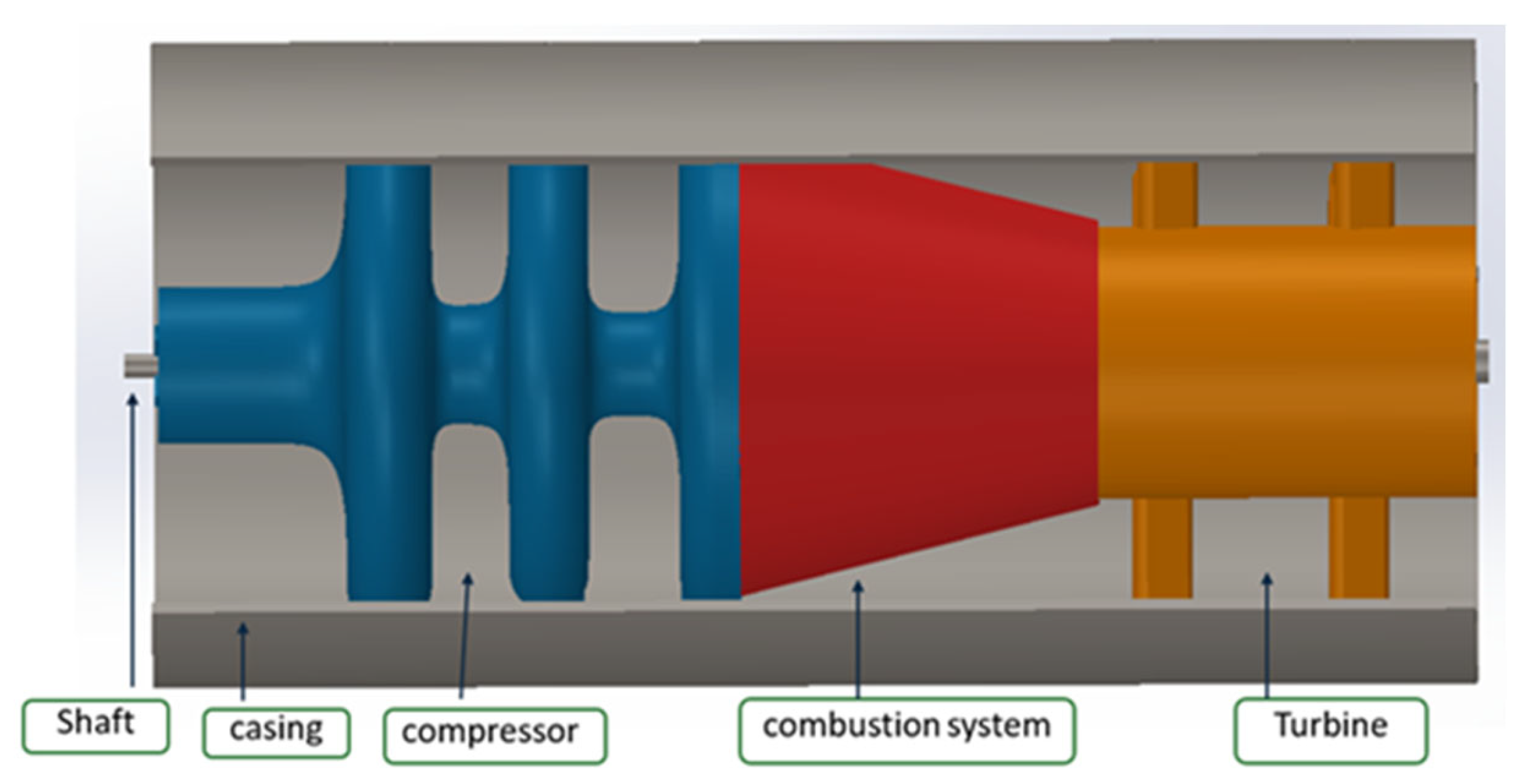
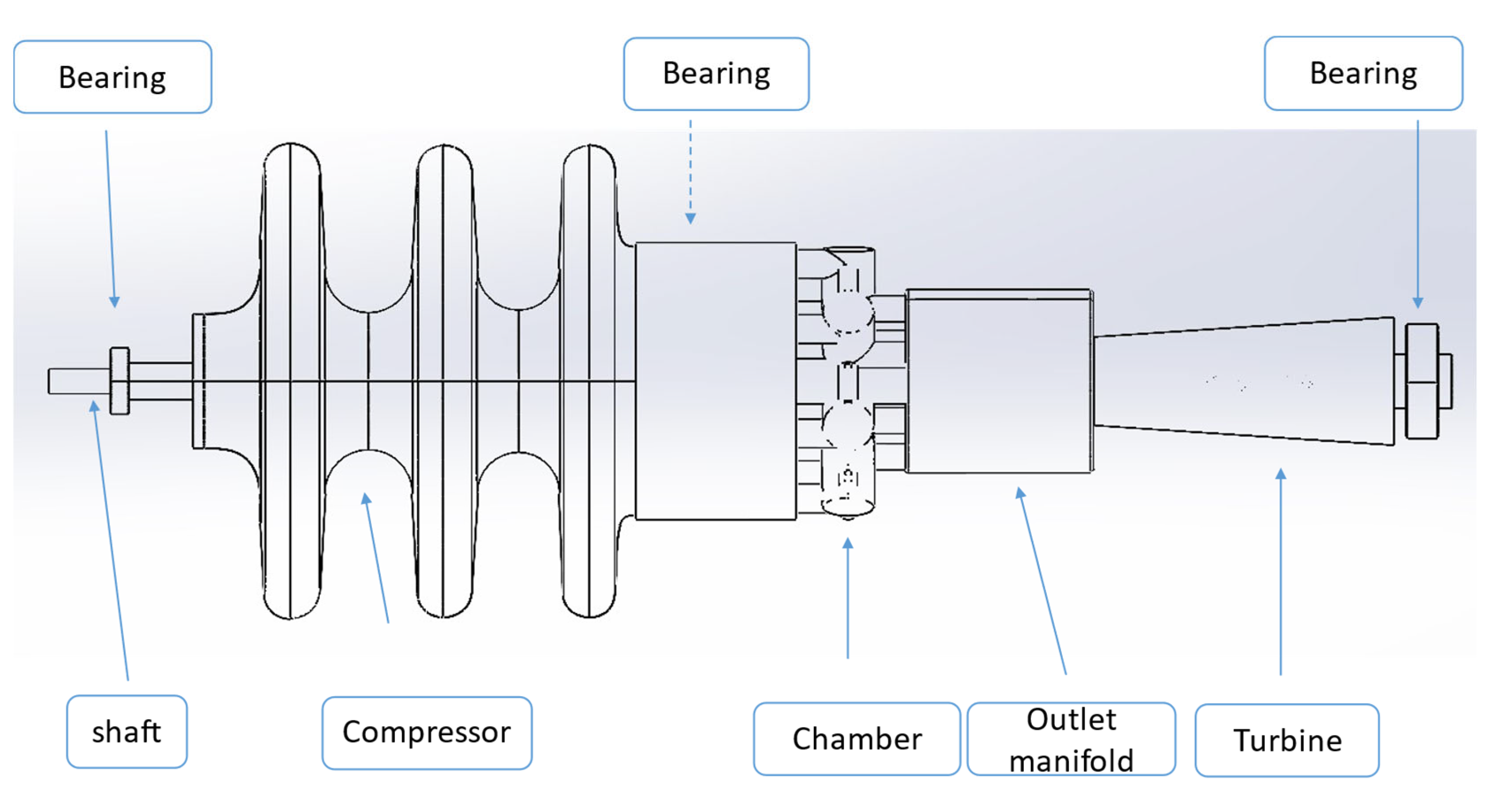
2. Conceptual Design

Considering the current state of the art, we established a design objective for a power output of up to 100 kW for a turbo gas system, with parameters including a pressure ratio Beta (β = 40), a turbine inlet temperature (TIT) of 1400 K, and a mass flow rate capable of operation up to 100,000 rpm. A conceptual design was developed, as illustrated in (Figure 1), incorporating the specified parameters. Numerical analysis was initiated using Ansys CFX to examine the flow characteristics in the micro-scaled geometry and the combustion characteristics of hydrogen-air combustion.
In accordance with the conceptual design, a preliminary design is then developed with overall dimensions of 150 mm in diameter and lower than 600 mm in length, as shown in Figure 2. It includes a shaft, bearings, a compressor, a combustion system, and a turbine that can be operated up to 100,000 rpm, generating a power output of about 70–100 kW, with an estimated system weight of 15 kg excluding the alternator.

3. Design Challenges

This section briefly outlines the primary obstacles that could be faced while building up the MGT at both the component level and the system level.

3.1. Component Level

Considering the combustion characteristics of hydrogen fuel, developing combustor technology for hydrogen combustion becomes even more complex. Major component-level difficulties have been addressed here.

3.1.1. Chamber

Major concerns are related to the high temperature since the mixture used to burn gases is 100% H2-air supplied, with an equivalency ratio of <0.4. According to preliminary numerical simulations done using Ansys Chemin, the temperature during combustion might even be higher than 2500 K. This is critical also in considering the material, taking into account the creep, corrosion, and fatigue resistance of the component.

3.1.2. Outlet Manifold
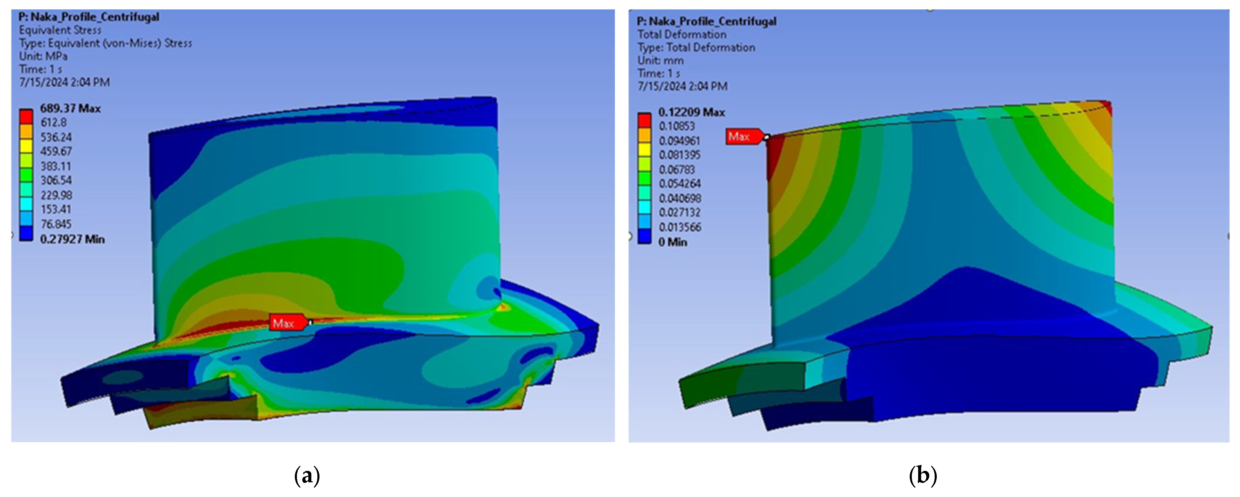
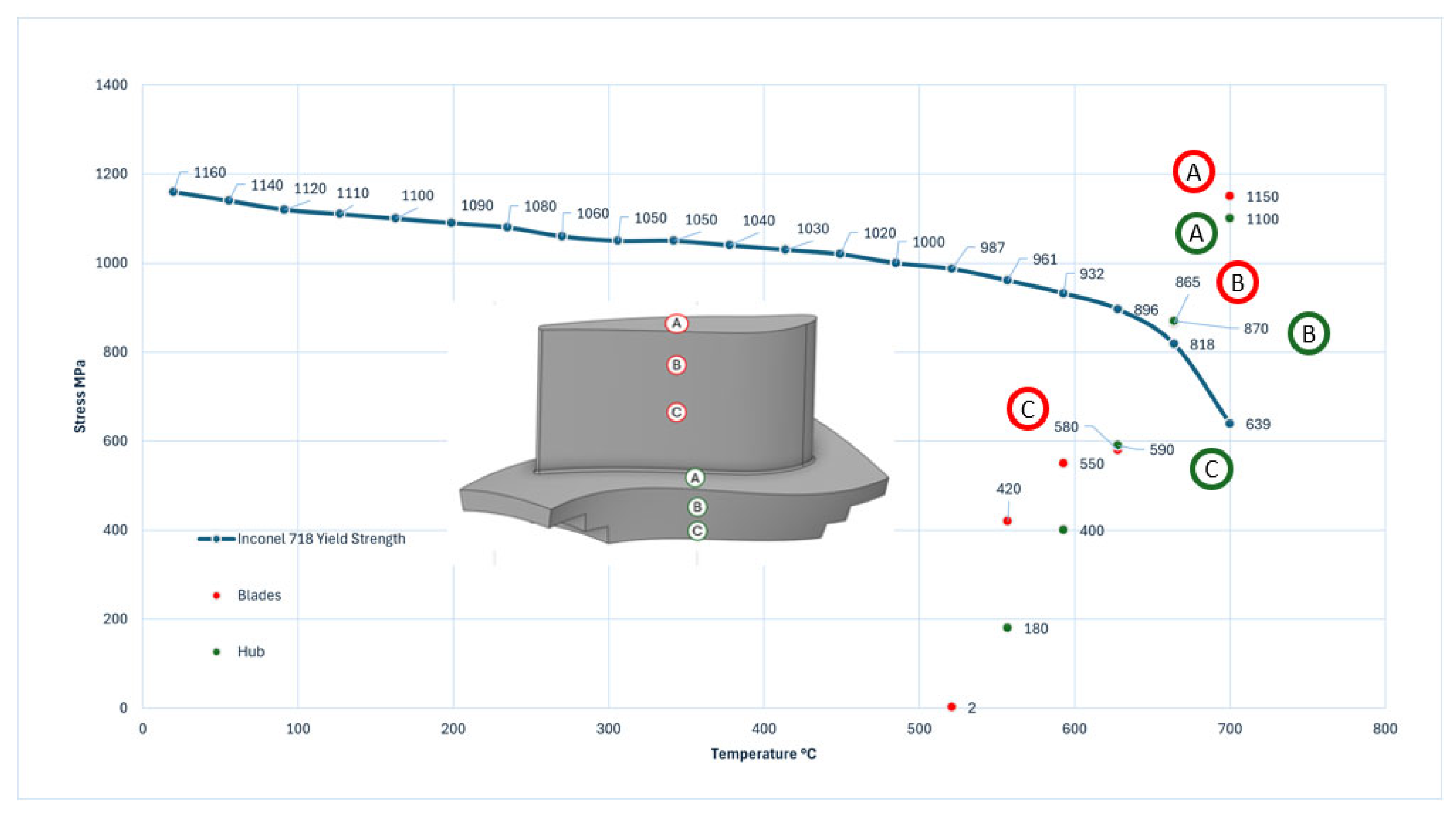
Chambers are connected to the 1st stage of the turbine by a manifold (see Figure 2) whose commitment is to optimize the flow from the chambers. The burning of hydrogen instead of natural gas increases the moisture content in the exhaust gas and, for this reason, can boost heat transfer to the hot gas turbine route components. To prevent component overheating, it will be necessary to modify the cooling techniques. This condition can increase the oxygen content with the transport gases, which leads to corrosion on the surface of the hot gas turbine route components and affects the thermal fatigue resistance.

3.1.3. Turbine

As the blades are responsible for extracting energy from the high temperature, high-pressure gas is produced by the combustor. Hot gases entering the 1st stage of the turbine, as impellers of turbines being micro scaled upon evaluating with help of Ansys mechanical observed there are no adverse effects with the centrifugal forces as boundary conditions. From Figure 3a, we can see the yield strength as 689 MPa with deformation of 0.12 mm (Figure 3b), which is much less than the chosen material Inconel-718 yield strength, which is 800 MPa.
Figure 4 is a plot of stress versus temperature for material Inconel-718 [12,13] data with the orange points extracted with the help of Ansys mechanical engineering data, upon which the data were evaluated by interpolating the Ansys CFX results to the Ansys mechanical-coupled (structural and thermal) analysis of the turbine blade (red points) and hub (green points), which are plotted considering some points as in the direction of flux.
Figure 4 is plot of stress vs temperature obtained from a coupled numerical analysis of CFD and Mechanical with the help of Ansys.steps followed for this plot: primarily the material data of Inconel – 718 yield strength vs temperature has been plotted which are blue in colour upon which different points obtained from the numerical analysis approach (interpolating the Ansys CFX results to the Ansys mechanical-coupled (structural and thermal) analysis of the turbine blade (red points) and hub (green points), which are plotted considering some points as in the direction of flux).
Typically, points below the slope often indicate that the component is safe, whereas above the slope suggests that the blade may affect the behavior of thermal fatigue, as in our case.

3.1.4. Bearings

As mentioned in Section 3, the system is designed to be operated at high centrifugal forces. We have defined four super-precision bearings that can run at extended speeds of up to 100,000 rpm with an air-oil lubrication system. The main challenge is defining an effective lubrication system for the bearing closest to the hot combustion system.

3.1.5. Shaft

The shaft rotates with the bearings holding rotating and stationary components operating at very high speeds, and the thermal effect from the hot gases brings up an additional challenging task.

3.2. MGT System Level

Due to the unique properties of hydrogen, as mentioned in Section 1, it is also crucial to evaluate the hydrogen concentration regarding the MGT level environment.
The combustion of hydrogen could potentially have an impact on the thermodynamics of the MGT, which could also result in the production of toxic nitrogen oxides.

3.2.1. Temperature Management

At the MGT level, as mentioned in Section 3.1, we have very high temperatures as flux passes from the chamber to the turbine after combustion as the manifold guides these hot gases into 1st stage of the turbine. Apart from cooling techniques, a well-defined mechanical coupling decreases the losses and increases the system efficiency with greater power output.

3.2.2. Operating Speed

As addressed previously in Section 3 about the operating speeds, concerning the MGT level as a primary step, we evaluate the system with the help of the Ansys mechanical extrapolating the Campbell diagram, as shown in Figure 5.
A Campbell diagram is a graphical representation that shows the natural frequencies of a rotating system as a function of its rotational speed. It also helps to understand potential resonance issues that might occur because of the interaction between the rotating components and the natural frequencies of the system.
Figure 5 typically displays the natural frequencies (or modes) of the structure on the vertical axis and the rotational speed on the horizontal axis. The slope (black line) represents exciting frequencies on which we can identify many red triangles in between the operating range of 0 to 100,000 rpm, which represents points of resonance. Different color codes speak about modes from the range of 0 to 100,000 rpm. Usually, modes at the initial speed can be studied using numerical analysis and should be mitigated by using some dampers. Increasing the damping ratio increases the stability of the system at the initial critical speeds as these absorb more energy. The later points do not affect much as the system will be running at the design speed. BW and FW in Figure 5 represent the swirl directions: if the rotation is in the direction of rotational velocity, it is called a forward swirl (FW), and if the rotation is in a counterclockwise direction with respect to rotational velocity, it is called a backward swirl (BW).

4. Pathway to Solutions

This section illustrates some possible solutions that can solve the challenges listed in Section 3. These solutions could help in mitigating the challenges either at the component level or at the system level.

4.1. System Level

4.1.1. Equivalence Ratio

The equivalence ratio [14,15,16] is defined as the ratio of the actual fuel/air ratio to the stoichiometric fuel/air ratio. When all the oxygen in the reaction is used up and the products contain no molecular oxygen (O2), stoichiometric combustion takes place.
The combustion is stoichiometric when the equivalence ratio is 1. In case the value is less than 1, the combustion is incomplete and lean, and if it is greater than 1, the combustion is rich [17,18,19]. In this specific case, an equivalence ratio in the range of 0.2–0.4 could be investigated, also considering the effective gasification.

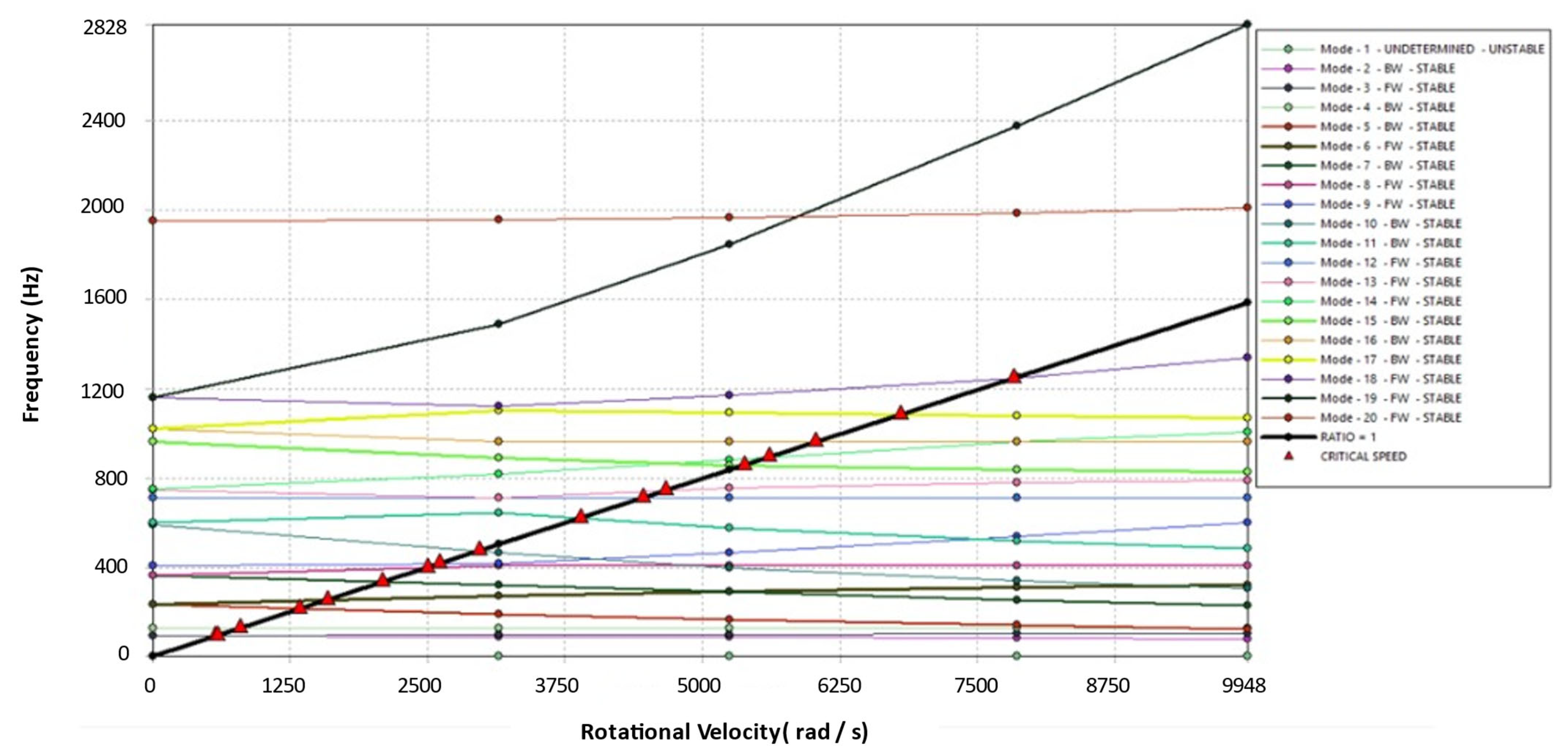
4.1.2. Vibrational Management

Considering the results shown in Section 3.2.2 and summarized in Figure 5, the vibrational problems in the MGT operating up to 100,000 rpm could affect the system behavior as they consume more energy at low rpm.
These vibrational problems could be mitigated at the system level by defining spacers, sealings, couplings and dampers, eventually giving their major contribution mechanically for safe operating conditions.

4.1.3. Temperature Management

Temperature challenges could be solved using techniques like choosing high-performance material, defining enough lubrication system, regular maintenance, reliability solutions or coating techniques.
Reliability solutions could be based on the comparison between coating costs and replacing costs of the most affected component. However, this solution could frequently be much more costly.
Coating techniques, in this case, could also be an interesting solution as they increase the output efficiency, thus studying different techniques suitable for MGTs.
The coating techniques methods that are most frequently employed to produce thin layers in ambient circumstances are coating deposition techniques. These coatings usually range in microns depending on the environment of the application.
Adopting coating solutions gives two different types of coating choices: Thermal Barrier Coatings (TBCs) and Environmental Barrier Coatings (EBCs).
In our case, Inconel-718 has been considered as it is well-reputed in the field of aerospace applications and turbomachinery. The present case scenario has a temperature of around (1600 K–1800 K), which is high considering the service temperature of Inconel-718, which is up to 978 K and can be coated using TBC solutions.
TBCs are refractory-oxide ceramic coatings applied on metal substrates. These techniques can be used in hot gas flow sections like chambers, turbines, manifolds, and afterburners to raise efficiency with an increased power output. Usually, these coatings are a stack up of different layers on the substrate (nickel alloy), bond coat, thermally grown oxide, and topcoat. These layers’ thickness depends on factors such as thermal conductivity, the thickness of coatings, etc. TBC fails if the TGO layer exceeds 20 microns.
As mentioned in Section 3, considering Inconel-718 as material, adopting TBC for our application could be a possible solution [20,21,22,23].
EBC is typically used with ceramic matrix composite (CMC) components. Considering blending it with ceramic could help to resolve the challenge. Lightweight composites called CMCs may be used in high-temperature, high-stress situations (up to 1482 °C) to minimize fuel usage in advanced gas turbines and other similar systems [24,25,26,27].
Because of their increased temperature capabilities, resilience to oxidation, and reduced weight, CMCs are groundbreaking for numerous kinds of applications. These coatings are used on the ceramic substrate, and these have a skeletal system of stacking up with different layers of coating like substrate (made of CMC in this case), bond coat, environmental coat, intermediate coat, and topcoat.
In this case, the use of a ceramic substrate motivates the selection of environmental coatings. They are crucial because the high temperature could potentially increase the NOx content. Catalytic converters, or afterburners, which can also boost power output and limit NOx content, could be the best option. On the other hand, lowering the equivalence ratio by adding more oxidizers could be an alternative solution. This is because the extra oxidizer could cool the system itself and lower the NOx level at the turbine outlet as well.

4.2. Component Level

As mentioned in Section 4.1.1, tuning the equivalence ratio or adopting coating techniques could help resolve the challenges for the components like the chamber, outlet manifold, and turbine blades.

4.2.1. Bearing

Providing a lubrication system could solve this challenge. Lubrication depends on the type of bearing, number of rows, breadth, and other factors in defining the amount of oil needed to lubricate a bearing. It is possible to use an equation found in the literature [28] to determine the approximate amount of oil needed.
Q = w d B
where
  • Q = quantity in mm3/h;
  • w = numerical coefficient = 0.01 mm/h;
  • d = internal bearing diameter;
  • B = bearing width in mm.
However, it is necessary to consider a high safety factor (even up to 20) to consider the specific operating conditions of the system. Otherwise, it will be necessary to use experimental tests to identify the current amount of oil needed.
Finally, the ratio of air could be determined by the range of temperature in the respective section.

4.2.2. Shaft

Evaluating the impeller’s scale of deformation with respect to operating conditions and maintaining minimum clearance between the rotating and stationary parts is mandatory. Estimating the shaft’s behavior using numerical modal analysis to determine the natural frequencies and associated mode shapes for the shaft needs to consider also stiffness changes due to stress stiffening; therefore, the presence of stress in a structure can alter its vibrational characteristics. In fact, typically, tensile stresses increase the structure’s frequency, and compressive stresses decrease the frequencies (pre-stressed modal analysis).
([K + S] − ωi2[M]) {φ}i = {0},
where
  • K = stiffness matrix;
  • S = stress stiffening matrix;
  • M = mass matrix;
  • ωi2 = n eigen values;
  • {φ}i = n eigen vectors;
  • n = number of degrees of freedom (DOF).
Computing stress stiffness matrix in linear analysis also considering stiffness and mass matrix in non-linear analysis helps in determining the exact behavior of the shaft.
Passing the cooling air or defining an internal cooling system for the shaft could help in overcoming the thermal-mechanical effects, too.

5. Conclusions

Due to the fact that hydrogen is a highly volatile and flammable element along with its wide flammability range, one safety concern with hydrogen is that it takes very little energy to ignite. Using more than the required amount of hydrogen also presents a larger chance of flashbacks. Hydrogen also produces more NOx emissions because of its higher combustion temperatures. Considering all the above mentioned steps a preliminary design has been developed for the MGT level which was studied with the help of hypothesis and numerical analysis. The numerical analysis helped to replicate the system, which helped to identify the challenges both at component and system levels at a very early stage which helped to eradicate above mentioned challenges with possible solutions as mentioned in section pathway to solutions like tuning equivalence ratio or defining a material to overcome the thermal challenges; also evaluated coating techniques for the hot gasway paths in order to use hydrogen as a substitute fuel for gas turbines to produce electricity without carbon footprints. The next step is to use the obtained results to introduce improvements to the various parts of the MGT and deepen the design of the system, realizing the system’s architecture, performing tests and eventually making the necessary upgradations on different parts both at component level and system level.

6. Patents

This research is connected to the international patent “Electrical energy generator device”, PCT/IB2018/052036 [11].

Author Contributions

Conceptualization, U.N.G., A.M. and A.G.; methodology, A.G. and A.M.; formal analysis, U.N.G. and A.G.; data curation, U.N.G., V.L.B. and A.G.; writing—original draft, U.N.G. and A.M.; writing—review and editing, U.N.G., V.L.B. and A.G.; supervision, A.M. and A.G. All authors have read and agreed to the published version of the manuscript.

Funding

This research received no external funding.

Institutional Review Board Statement

Not applicable.

Informed Consent Statement

Not applicable.

Data Availability Statement

No new data were created or analyzed in this study. Data sharing is not applicable to this article.

Acknowledgments

Numerical fluid dynamics behavior of the compressor and turbine has been evaluated with the help of Pentaparthi Sanjay Reddy.

Conflicts of Interest

Author Angelo Minotti is the Chief Executive Officer of the company MIEEG s.r.l. The remaining authors declare that the research was conducted in the absence of any commercial or financial relationships that could be construed as a potential conflict of interest.

References

  1. The Future of Hydrogen—Analysis—IEA. Available online: https://www.iea.org/reports/the-future-of-hydrogen (accessed on 12 September 2024).
  2. Aliberti, D.; Ortenzi, F.; La Battaglia, V.; Marini, S.; Vellucci, F. Evaluation of the Efficiency of a Hybrid ICE Vehicle Fuelled with Hydrogen Compared with a Fuel Cell Vehicle, Based on a Simulation Model. J. Phys. Conf. Ser. 2023, 2648, 012082. [Google Scholar] [CrossRef]
  3. Statista Largest Operational Coal Power Plants in the EU by Capacity 2021. Available online: https://www.statista.com/statistics/1264199/largest-operational-coal-power-plants-by-capacity-in-the-eu-27/ (accessed on 12 September 2024).
  4. European Turbine Network (ETN Global); ETN Secretariat. The Path Towards a Zero-Carbon Gas Turbine. 2019. Available online: https://api.semanticscholar.org/CorpusID:211166022 (accessed on 12 September 2024).
  5. Barati, S.; De Santoli, L.; Lo Basso, G. Modeling and Analysis of a Micro Gas Turbine Fuelled with Hydrogen and Natural Gas Blends. E3S Web Conf. 2021, 312, 08012. [Google Scholar] [CrossRef]
  6. Banihabib, R.; Lingstädt, T.; Wersland, M.; Kutne, P.; Assadi, M. Development and Testing of a 100 kW Fuel-Flexible Micro Gas Turbine Running on 100% Hydrogen. Int. J. Hydrogen Energy 2024, 49, 92–111. [Google Scholar] [CrossRef]
  7. Banihabib, R.; Assadi, M. A Hydrogen-Fueled Micro Gas Turbine Unit for Carbon-Free Heat and Power Generation. Sustainability 2022, 14, 13305. [Google Scholar] [CrossRef]
  8. Zhou, H.; Xue, J.; Gao, H.; Ma, N. Hydrogen-Fueled Gas Turbines in Future Energy System. Int. J. Hydrogen Energy 2024, 64, 569–582. [Google Scholar] [CrossRef]
  9. Gas Factsheet|Www.Acer.Europa.Eu. Available online: https://www.acer.europa.eu/gas-factsheet (accessed on 12 September 2024).
  10. Renewable Energy. Available online: https://www.eea.europa.eu/en/topics/in-depth/renewable-energy (accessed on 12 September 2024).
  11. Minotti, A. Electrical Energy Generator Device PCT/IB2018/05203. Available online: https://patents.google.com/patent/WO2018173012A1/en?oq=PCT%2fIB2018%2f052036 (accessed on 12 September 2024).
  12. Baldi, N.; Giorgetti, A.; Palladino, M.; Giovannetti, I.; Arcidiacono, G.; Citti, P. Study on the Effect of Inter-Layer Cooling Time on Porosity and Melt Pool in Inconel 718 Components Processed by Laser Powder Bed Fusion. Materials 2023, 16, 3920. [Google Scholar] [CrossRef] [PubMed]
  13. Ciappi, A.; Giorgetti, A.; Ceccanti, F.; Canegallo, G. Technological and Economical Consideration for Turbine Blade Tip Restoration through Metal Deposition Technologies. Proc. Inst. Mech. Eng. Part C J. Mech. Eng. Sci. 2021, 235, 1741–1758. [Google Scholar] [CrossRef]
  14. Sun, J.; Liu, Q.; Gu, M.; Wang, Y. Effect of Equivalence Ratio on Pollutant Formation in CH4O/H2/NH3 Blend Combustion. Molecules 2023, 29, 176. [Google Scholar] [CrossRef] [PubMed]
  15. Moroshkina, A.; Ponomareva, A.; Mislavskii, V.; Sereshchenko, E.; Gubernov, V.; Bykov, V.; Minaev, S. Activation Energy of Hydrogen–Methane Mixtures. Fire 2024, 7, 42. [Google Scholar] [CrossRef]
  16. Makaryan, I.A.; Sedov, I.V.; Salgansky, E.A.; Arutyunov, A.V.; Arutyunov, V.S. A Comprehensive Review on the Prospects of Using Hydrogen–Methane Blends: Challenges and Opportunities. Energies 2022, 15, 2265. [Google Scholar] [CrossRef]
  17. Luo, Q.-H.; Hu, J.-B.; Sun, B.-G.; Liu, F.-S.; Wang, X.; Li, C.; Bao, L.-Z. Effect of Equivalence Ratios on the Power, Combustion Stability and NOx Controlling Strategy for the Turbocharged Hydrogen Engine at Low Engine Speeds. Int. J. Hydrogen Energy 2019, 44, 17095–17102. [Google Scholar] [CrossRef]
  18. Liu, Q.; Liu, Z.; Peng, S.; Liu, C.; Liu, C.; Liu, L.; Zhou, R.; Zhi, S.; Fan, T.; Li, P. Effects of Hydrogen Blending Ratio and Equivalence Ratio on the Dynamic Characteristics of Deflagration Shock Waves of CH4/H2 Mixtures. ACS Omega 2024, 9, 23853–23863. [Google Scholar] [CrossRef] [PubMed]
  19. Kanti, R.M.; Kawahara, N.; Tomita, E.; Fujitani, T. Effect of Equivalence Ratio on Combustion Characteristics in a Hydrogen Direct-Injection SI Engine; Springer eBooks: Berlin/Heidelberg, Germany, 2012; pp. 97–102. [Google Scholar]
  20. Barwinska, I.; Kopec, M.; Kukla, D.; Senderowski, C.; Kowalewski, Z.L. Thermal Barrier Coatings for High-Temperature Performance of Nickel-Based Superalloys: A Synthetic Review. Coatings 2023, 13, 769. [Google Scholar] [CrossRef]
  21. Boissonnet, G.; Chalk, C.; Nicholls, J.R.; Bonnet, G.; Pedraza, F. Thermal Insulation of YSZ and Erbia-Doped Yttria-Stabilised Zirconia EB-PVD Thermal Barrier Coating Systems after CMAS Attack. Materials 2020, 13, 4382. [Google Scholar] [CrossRef] [PubMed]
  22. Mondal, K.; Nuñez, L.; Downey, C.M.; Van Rooyen, I.J. Recent Advances in the Thermal Barrier Coatings for Extreme Environments. Mater. Sci. Energy Technol. 2021, 4, 208–210. [Google Scholar] [CrossRef]
  23. Bogdan, M.; Peter, I. A Comprehensive Understanding of Thermal Barrier Coatings (TBCs): Applications, Materials, Coating Design and Failure Mechanisms. Metals 2024, 14, 575. [Google Scholar] [CrossRef]
  24. Xiao, S.; Li, J.; Huang, P.; Zhang, A.; Tian, Y.; Zhang, X.; Zhang, J.; Ryu, J.; Han, G. Evaluation of Environmental Barrier Coatings: A Review. Int. J. Appl. Ceram. Technol. 2023, 20, 2055–2076. [Google Scholar] [CrossRef]
  25. Lü, K.; Huang, Y.; Xu, M.; Xie, Y.; Deng, L.; Dong, S.; Jiang, J.; Chen, W.; Cao, X. Multi-Layered Environmental Barrier Coatings Designed on Basis of YbTaO4-Ta2O5 Composites for Protecting SiCf/SiC Composites. J. Eur. Ceram. Soc. 2024, 44, 3525–3536. [Google Scholar] [CrossRef]
  26. Lee, K.; Zhu, D.; Wiesner, V.L.; Mark, V.R.; Kashyap, T.; Wiesner, V. Environmental Barrier Coatings for Ceramic Matrix Composites—An Overview. Available online: https://ntrs.nasa.gov/citations/20170004751 (accessed on 12 September 2024).
  27. Vaßen, R.; Bakan, E.; Gatzen, C.; Kim, S.; Mack, D.E.; Guillon, O. Environmental Barrier Coatings Made by Different Thermal Spray Technologies. Coatings 2019, 9, 784. [Google Scholar] [CrossRef]
  28. SKF Air-Oil Lubrication Units and Mixing Valves Product Series OLA, MV and 161. Available online: https://www.skf.com/uk/products/lubrication-management/system-components/supply-units/oil-and-air-lubrication/ola (accessed on 7 March 2025).
Figure 1. Conceptual design.
Engproc 85 00045 g001
Figure 2. Preliminary design.
Engproc 85 00045 g002
Figure 3. Structural simulation of the blade profile: (a) impeller’s equivalent stress scale; (b) impeller’s deformation scale.
Engproc 85 00045 g003
Figure 4. Stress versus temperature obtained by numerical simulation at different positions of the blade and hub.
Engproc 85 00045 g004
Figure 5. Campbell diagram (rpm vs Hz): forward swirls (FWs), backward swirls (BWs).
Engproc 85 00045 g005
Disclaimer/Publisher’s Note: The statements, opinions and data contained in all publications are solely those of the individual author(s) and contributor(s) and not of MDPI and/or the editor(s). MDPI and/or the editor(s) disclaim responsibility for any injury to people or property resulting from any ideas, methods, instructions or products referred to in the content.

