Abstract
Wound rotor electric motors offer low production costs and environmental sustainability, making them preferable over rare-earth-based motors, particularly at low speeds. However, in automotive applications, the demand for higher specific powers and rotational speeds increases the structural challenges for wound rotors. While commercial Finite Element simulations integrate structural and electromagnetic needs, they could not immediately highlight the influence of single parameters on rotor stress. This paper introduces a simplified analytical methodology for the structural analysis of wound rotors, validated against Finite Element simulations, showing strong agreement. This approach is particularly useful during the early design stages for guiding preliminary geometry definitions.
1. Introduction
Wound rotor electric motors are characterized by low production costs and significant environmental sustainability, making them preferable to motors that use rare-earth materials, especially when low revving speeds are required [1,2,3]. In the automotive field, the constant need to increase specific power and, consequently, rotational speed creates a scenario that makes the use of wound rotors more challenging due to the inevitable increase in the stresses they are subjected to. Current commercial Finite Element software can integrate structural and electromagnetic requirements, but they do not clearly highlight the influence of the single design parameters on the stress state of the rotor [4,5]. In contrast, an analytical approach can explicitly show the dependencies of loads and stresses on design specifications and component geometries. This contribution proposes a simplified analytical methodology for the structural analysis of wound rotors in electric motors. This methodology is applied to the analysis of a prototype electric motor for heavy-duty vehicle traction. The results of the analytical calculations were also compared with Finite Element simulations, revealing a substantial correspondence between the two. Both plane stress and plane strain modelling are considered. The analysis includes a laminated steel sheet, the corresponding portion of the copper winding, and the influence of the shaft on which the rotor is mounted. The rotor body is modelled as a hollow cylinder with teeth modelled as T-shaped geometric structures radially arranged on the outer edge, around which the copper wires are wound. Four critical sections were identified to calculate the acting loading characteristics and the resulting stresses (see Figure 1).
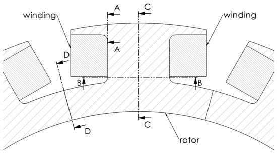
Figure 1.
The portion of the wound rotor analyzed and the four critical sections identified (A–A, B–B, C–C and D–D).
This paper is organized as follows. In Part 2, the main characteristics of the motor under examination and the properties of the materials involved are described. Part 3 shows the simulation of the rotor performed with Finite Elements (FEs). These results will be used to compare and possibly validate the analytical calculations. In Part 4, section A-A is considered. This corresponds to the crossbar of the T-shape, which holds the copper winding and is mainly subjected to bending stress due to the centrifugal force generated by the mass of the winding and the crossbar itself. Part 5 examines section B-B, which corresponds to the base of the central body of the T-shape and is primarily subjected to normal stress due to centrifugal contributions, as well as the bending moment and shear load generated by the electromagnetic force. Part 6 focuses on Sections C-C and D-D, which are two radial sections of the back iron, located at the tooth and midway between two teeth, respectively. Finally, some conclusions end the manuscript.
2. The Motor Under Investigation
Table 1 collects the main characteristics of the motor under investigation.

Table 1.
Main parameters of the motor under investigation.
Regarding the materials, a standard iron commonly used for electric motor rotors was selected. As for the windings, an equivalent homogeneous material was considered to account for the slot fill factor. However, it was crucial to accurately determine the density to properly calculate the centrifugal force generated, while the other characteristics were of marginal importance. These materials were considered linear elastic for both the analytical treatment and the numerical forecasts. Table 2 presents the material properties.
Table 2.
Main parameters of the motor under investigation.
3. The Finite Element Analyses
Figure 2a illustrates the FE model used in the analysis. The commercial software Marc2024 was employed. A twelfth of the rotor was considered, with appropriate periodicity conditions applied. Since the stress and strain in each layer are assumed to be unaffected by their axial location, a 2D FE model was implemented instead of a 3D one. This model includes a portion of the rotor and two sections of the winding. As a result of a sensitivity analysis, approximately 45,000 triangular and quadrilateral planar elements were used. Centripetal acceleration and a pressure of 6 MPa, to simulate the interference fit between the rotor and the shaft on the inner edge, were applied as boundary conditions. The torque generated by the motor was not included as it was deemed negligible, as later confirmed by analytical calculations.
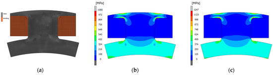
Figure 2.
The FE model: (a) The computational domain; von Mises stress contour plot. (b) Plane strain. (c) Plane stress.
The structural behaviour of the laminations was analyzed by considering two edge cases. The first case corresponds to laminations located in the middle of the active length of the motor, while the second case pertains to laminations at the axial periphery. Specifically, the first case is addressed by the plane strain hypothesis, while the second case is governed by the plane stress hypothesis. Figure 2b,c present the simulation results. Figure 2b shows the von Mises stresses for the plane strain case, while Figure 2c shows the von Mises stresses for the plane stress case. The two simulations yield slightly different results due to the presence of axial stress in the plane strain scenario. In the analytical discussion, both modelling strategies will be considered where applicable. It is also worth noting that the highest stresses are located on the laminate and with local maxima registered at the sections identified in Figure 1.
4. Section A-A: The Crossbar of the T-Shape
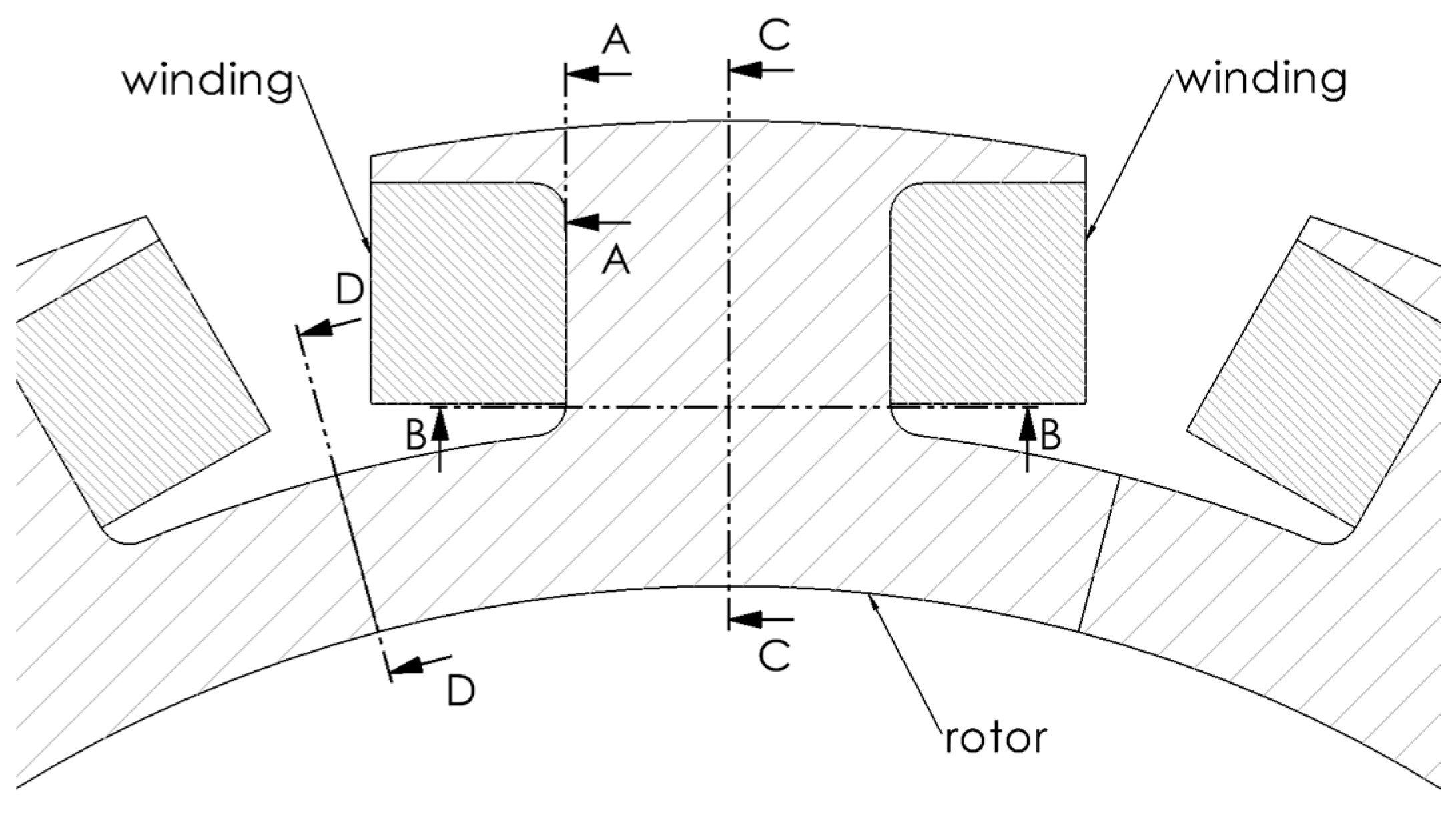
Figure 3a shows a detailed view of section A-A. The crossbar of the T-shape can be considered to be a cantilever beam fixed at the region identified by section A-A and subjected to the forces Fcw and FcT, which are the centrifugal forces generated by the mass of the winding and the mass of the T-shape crossbar, respectively (see Figure 3b). The resultant force of the winding was calculated considering a uniform contact pressure at the interface with the crossbar.
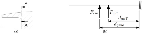
Figure 3.
Section A-A: the crossbar of the T-shape: (a) detailed view; (b) analytical model.
The bending moment acting on section A-A can therefore be calculated as
where dgxw and dgxT are the distances between the centre of gravity of the winding and the crossbar of the T-shape, respectively, from section A-A.
The bending stress can therefore be determined as
where WA−A is the section modulus of section A-A, and KtA−A is the notch effect coefficient, here considered to be equal to 1.4 (see [6], page 193, Chart 3.7).
In the case of plane stress, σA−Ax coincides with the von Mises stress. However, in the case of plane strain, the stress arising in the axial direction must also be considered:
where νr is the Poisson’s ratio of the iron material used for the rotor.
Table 3 shows the results of the analytical calculations and compares them with the numerical forecasts. Specifically, it focuses on the stress peaks located at the fillet. The analytical values are close to those obtained from the simulations, and the discrepancy can be ascribed to the uncertainty in the notch effect coefficient. The analytical formulas indicate that to reduce the stresses at section A-A, it is necessary to either decrease the centrifugal forces or minimize the overhang of the T-shape crossbar. While it may be challenging to reduce the masses and speeds to meet the motor’s performance targets, adjusting the geometry of the pole to limit the protrusion of the T-shape crossbar could offer a more feasible solution.
Table 3.
Section A-A, comparison of the results.
5. Section B-B: The Central Body of the T-Shape
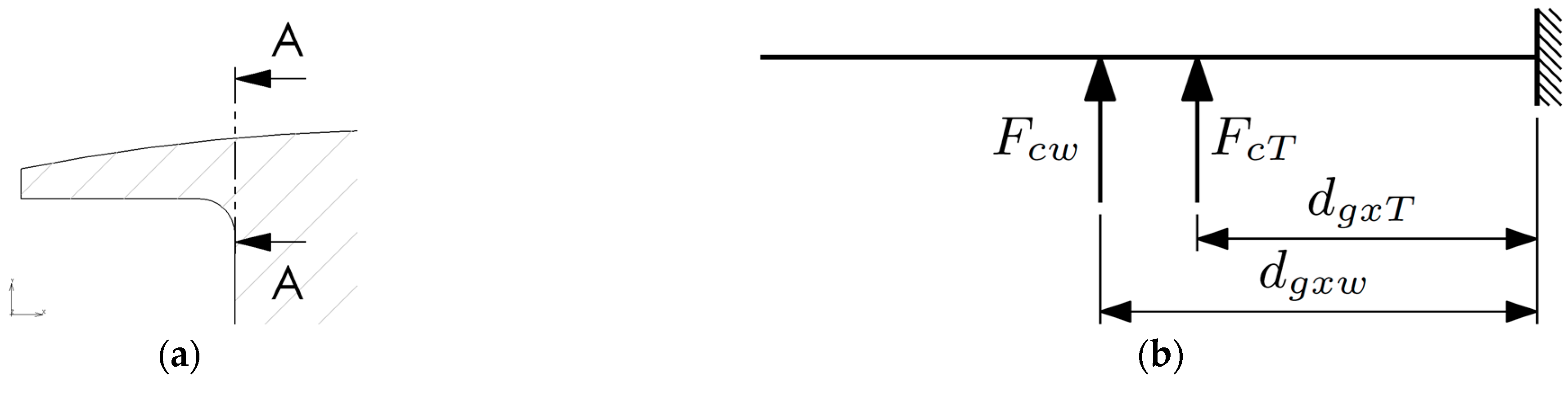
Figure 4a shows a detailed view of section B-B. The central body of the T-shape can be considered to be a cantilever beam fixed at the region identified by section B-B and subjected to the forces Fcp and Fsw, which are, respectively, the tensile force generated by the mass of the winding and of the pole and the shear force calculated at the air gap necessary to create the required torque (see Figure 4b).
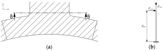
Figure 4.
Section B-B: the central body of the T-shape: (a) detailed view; (b) analytical model.
Fsw generates shear and bending moment on section B-B.
The shear stress can be calculated as
where AB−B is the cross-sectional area of section B-B, and Fsw is given by
where Tm is the torque of the electric motor, np is the number of poles, and rgw is the centroidal radius of the winding relative to the axis of rotation. For this specific motor, the calculations show that Fsw is quite low (808 N) due to the large size of the motor addressed in this case study. As a result, the shear stress is minimal (0.4 MPa) and can be considered negligible compared to the stresses caused by other factors.
Moving on to the bending stress generated on section B-B,
where dyr is the distance between the external profile of the rotor and section B-B and WB−B is the section modulus of section B-B. In this case, the stress induced by the bending moment is also negligible (0.9 MPa).
However, the normal stress acting on section B-B cannot be neglected and is given by
where Fcp is the centrifugal force generated by the pole, including the entire T-shape and winding mass, AB-B is the cross-sectional area of the resisting section, and KtB-B is the notch effect coefficient, here considered equal to 2.75 (see [6], page 184, Chart 3.1).
Table 4 shows the results of the analytical calculations and compares them with the numerical forecasts. In this case, it appears that the resisting section is unnecessarily large, suggesting that the designer could consider increasing the space allocated for the winding, potentially reducing the rotor’s external dimensions. Once again, the analytical values are consistent with those from the simulations, with the discrepancy likely attributed to uncertainties in the notch effect coefficient. Additionally, the region of interest is close to the back iron, which experiences loading conditions more similar to a disc than a beam.
Table 4.
Section B-B, comparison of the results.
6. Sections C-C and D-D: The Back Iron
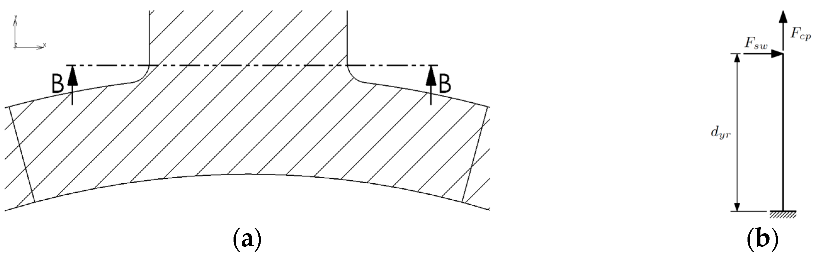
Figure 5a shows a detailed view of sections C-C and D-D. Considering the quasi-axisymmetric characteristic of the problem and with the aim of deriving a more robust and valid analytical model out of the applicability of the beam theory, in this case, a modelling approach based on the theory of elasticity is presented [7,8,9]. The analytical solution relies on a classical series solution in polar coordinates attributed to Michell [10]. This planar solution is particularly well suited for modelling discs subjected to different types of loading along their inner and outer edges, inspired by the methodology presented in [11].
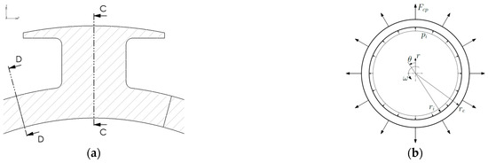
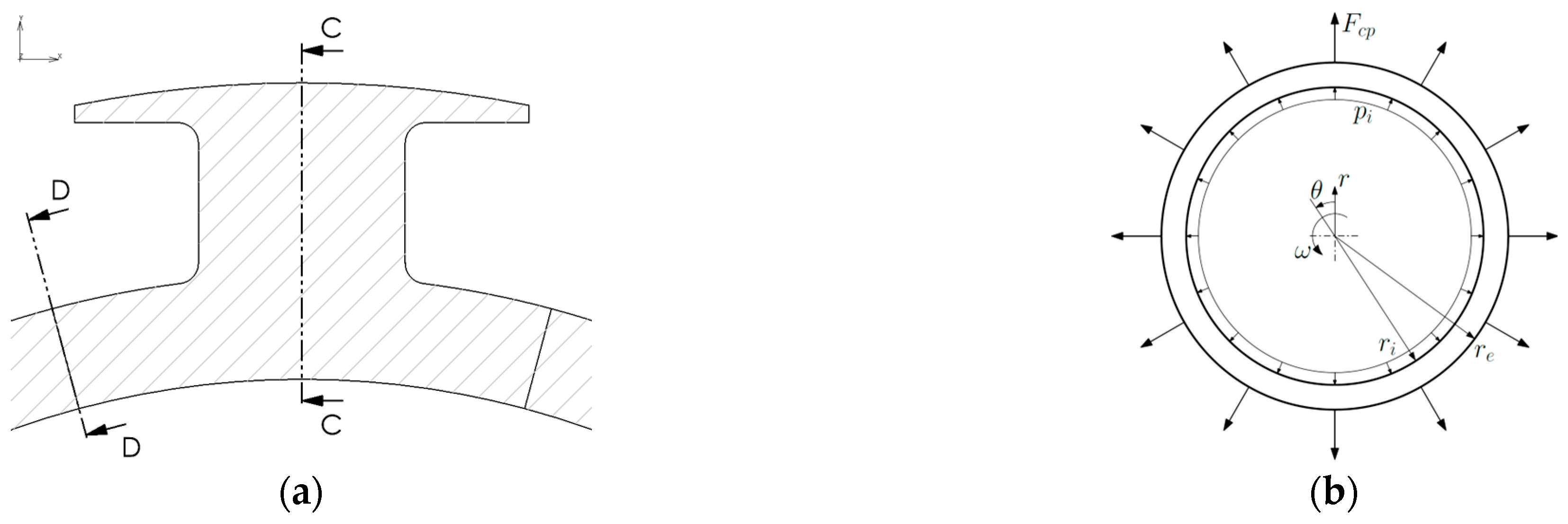
Figure 5.
Sections C-C and D-D: the back iron: (a) detailed view; (b) analytical model.
The problem was modelled as a hollow disc subjected to concentrated loads (Fcp) at the outer edge, corresponding to the centrifugal force of each of the twelve rotor poles. The disc is also loaded by the centrifugal force generated by its own rotation (ω) and by the pressure at the inner edge due to the interference fit with the shaft (pi), as shown in Figure 5b. To ensure the validity of the comparison with analytical calculations, the interference between the disc and the shaft was represented by applying a distributed pressure, as required by Mitchell’s theorem. While it is possible to simulate the interference more realistically, for example, by introducing a contact body representing the shaft with a proper interference fit, such an approach would impose displacement constraints, making it incompatible with the hypotheses of the theorem. This method was, therefore, avoided to preserve consistency with the analytical model.
The appropriate form of Airy’s stress function, Φ, expressed in polar coordinates in terms of a Fourier series, is (see [7], p. 119)
where r is a general radius, and the origin of the angular variable θ is defined by Figure 5b. In addition, the stresses expressed in terms of Φ are (see [9], p. 66)
The boundary conditions to be applied to the disc are discussed in the following.
At the inner radius, radial and tangential stresses are defined as
where the pressure, pi, mimics the interference fit with the shaft.
Twelve concentrated loads, Fcp, were applied at the outer radius, one for each pole. Specifically, these concentrated loads were applied using a trigonometric series corrected by the Lanczos factor [12] to smooth oscillations:
These boundary conditions must be applied to each harmonic, affecting the radial and tangential stresses along the outer radius of the disc as described by Equation (9) through the stress function Φ in Equation (8).
In addition, the centrifugal load related to the disc’s mass was incorporated using different methods for plane strain and plane stress conditions [13,14]. Specifically, for the plane strain condition, the approach considers the displacement u:
For the plane stress case, the following formulation was used:
where ρr is the material density of the rotor. The stresses caused by the centrifugal loading (σrrc, σθθc and σrθc) were achieved and the constants D1 and D2 were then determined by applying the following boundary conditions:
Finally, the stresses generated by the interference fit pressure and the load on the outer radius were added to the stresses caused by the centripetal acceleration.
The analytical results were subsequently compared with the numerical forecasts. Table 5 shows the von Mises stress results at the inner radius along section C-C.
Table 5.
Section C-C, inner radius, comparison of the results.
Table 6 and Table 7 compare the von Mises stress results at the inner and outer radius along section D-D, respectively.
Table 6.
Section D-D, inner radius, comparison of the results.
Table 7.
Section D-D, outer radius, comparison of the results.
The results demonstrate an alignment between the simplified analytical calculations and the simulation outcomes. However, there are noticeable limitations to accurately calculate the stresses in the back iron region, particularly where the T-shape is involved, i.e., section C-C. In this area, the load is not applied as a concentrated force but is instead distributed across the entire T-shape section. Moreover, the increased stiffness of the T-shape significantly alters the stress distribution compared to a simple disc.
7. Conclusions
This work has presented a simplified analytical methodology for calculating stresses in the most critical and defining areas of the geometry of wound rotors for electric motors. Four key regions were identified: the crossbar of the T-shape (section A-A), the body of the T-shape (section B-B), the back iron section beneath the T-shape (section C-C), and the back iron section between poles (section D-D). The analytical results were compared with FE analysis. For section A-A, the discrepancy in the results was never greater than 12%, while for section B-B, this difference was around 11%. Although the real loading conditions and the beam theory methodology leave little room for ambiguity, the presence of notches introduces some uncertainty in selecting the appropriate notch effect coefficient. For sections C-C and D-D, beam theory was abandoned in favour of elasticity theory. The proposed methodology resulted in discrepancies of 24% for section C-C and no more than 18% for section D-D. These results justify the applicability of the proposed method, especially in the early stages of designing a wound electric rotor, when evaluating different geometries in the early stage of the design process. In the future, this methodology could be improved by reconsidering the model of the back iron used in the theory of elasticity, where the highest errors were registered compared to Finite Element forecasts. In particular, a series of square waves could be applied to the outer radius of the back iron, instead of using a concentrated load, to better approximate the actual load distribution.
Author Contributions
All authors contributed equally to this work. All authors have read and agreed to the published version of the manuscript.
Funding
This research was financed by European Union-Next generation EU trough the “PIANO NAZIONALE DI RIPRESA E RESILIENZA (PNRR)–MISSIONE 4 COMPONENTE 2, “Dalla ricerca all’impresa”, INVESTIMENTO 1.4, (CN00000023). In the context of the “Sustainable Mobility Center (Centro Nazionale per la Mobilità Sostenibile–CNMS)” - Spoke 13.
Institutional Review Board Statement
Not applicable.
Informed Consent Statement
Not applicable.
Data Availability Statement
Data are unavailable due to confidentiality reasons.
Conflicts of Interest
The authors declare no conflicts of interest.
References
- Madonna, V.; Giangrande, P.; Galea, M. Electrical Power Generation in Aircraft: Review, Challenges, and Opportunities. IEEE Trans. Transp. Electrif. 2018, 4, 646–659. [Google Scholar] [CrossRef]
- Wang, Y.; Nuzzo, S.; Zhang, H.; Zhao, W.; Gerada, C.; Galea, M. Challenges and Opportunities for Wound Field Synchronous Generators in Future More Electric Aircraft. IEEE Trans. Transp. Electrif. 2020, 6, 1466–1477. [Google Scholar] [CrossRef]
- Guo, H.; Sun, G.; Ding, X.; He, X.; Shan, Z.; Xu, J.; Zhao, Y.; Ju, L. Comprehensive Analysis and Solution of Voltage Build-Up Failure in Aircraft PM-Assisted Reluctance Starter/Generator System. IEEE Trans. Ind. Electron. 2024, 71, 171–182. [Google Scholar] [CrossRef]
- Guiducci, A.; Barbieri, S.G.; Nuzzo, S.; Batater, D.; Berni, F.; Cicalese, G.; Fontanesi, S.; Franceschini, G. Refined Structural Design and Thermal Analyses of a High-Speed Wound-Field Generator for the More Electrical Aircraft. In Proceedings of the 2023 IEEE Workshop on Electrical Machines Design, Control and Diagnosis (WEMDCD), Newcastle upon Tyne, UK, 13–14 April 2023; pp. 1–6. [Google Scholar] [CrossRef]
- Puglisi, F.; Barbieri, S.G.; Mantovani, S.; Devito, G.; Nuzzo, S. Multi-Physics and Multi-Objective Optimization of a Permanent Magnet-Assisted Synchronous Reluctance Machine for Traction Applications. Proc. Inst. Mech. Eng. C J. Mech. Eng. Sci. 2024, 238, 7945–7962. [Google Scholar] [CrossRef]
- Pilkey, W.D.; Pilkey, D.F. Peterson’s Stress Concentration Factors; Wiley: Hoboken, NJ, USA, 2007; ISBN 9780470048245. [Google Scholar]
- Barber, J.R. Elasticity; Gladwell, G.M.L., Ed.; Solid Mechanics and Its Applications; Springer Netherlands: Dordrecht, The Netherlands, 2010; Volume 172, ISBN 978-90-481-3821-0. [Google Scholar]
- Soutas-Little, R.W. Elasticity; Dover Publications: New York, NY, USA, 1999; ISBN 0486406903. [Google Scholar]
- Timoshenko, S.; Goodier, J.N. Theory of Elasticity; McGraw-Hill Book Company: New York, NY, USA, 1934; ISBN 0070858055. [Google Scholar]
- Michell, J.H. On the Direct Determination of Stress in an Elastic Solid, with Application to the Theory of Plates. Proc. Lond. Math. Soc. 1899, s1–31, 100–124. [Google Scholar] [CrossRef]
- Strozzi, A.; Baldini, A.; Giacopini, M.; Rivasi, S.; Rosi, R. Maximum Stresses in a Taper-shanked Round-ended Lug Loaded by an Oblique Concentrated Force. Strain 2007, 43, 109–118. [Google Scholar] [CrossRef]
- Lanczos, C. Applied Analysis; Dover Publications: New York, NY, USA, 1988; ISBN 048665656X. [Google Scholar]
- Kelly, P. Solid Mechanics Part I: An Introduction to Solid Mechanics. Available online: https://pkel015.connect.amazon.auckland.ac.nz/SolidMechanicsBooks/Part_I/index.html (accessed on 1 September 2024).
- Kelly, P. Solid Mechanics Part II: Engineering Solid Mechanics-Small Strain. Available online: https://pkel015.connect.amazon.auckland.ac.nz/SolidMechanicsBooks/Part_II/index.html (accessed on 1 September 2024).

Disclaimer/Publisher’s Note: The statements, opinions and data contained in all publications are solely those of the individual author(s) and contributor(s) and not of MDPI and/or the editor(s). MDPI and/or the editor(s) disclaim responsibility for any injury to people or property resulting from any ideas, methods, instructions or products referred to in the content. |
© 2025 by the authors. Licensee MDPI, Basel, Switzerland. This article is an open access article distributed under the terms and conditions of the Creative Commons Attribution (CC BY) license (https://creativecommons.org/licenses/by/4.0/).