Abstract
This study investigates the effect of a non-zero fillet radius, ρ, on the fatigue behaviour of notched components under uniaxial loading. A new diagram is introduced, which discusses the relationship between the notch tip radius and the fatigue limit. It also identifies a critical radius, ρ**, precisely marking the transition from sharp to blunt notch behaviour. Additionally, its application to the “stop-hole” technique is considered, where both material properties and geometric characteristics are analysed, demonstrating that introducing a fillet radius can improve fatigue resistance.
1. Introduction
In mechanical engineering, notches are commonly encountered, often characterised by an extremely small fillet radius, ρ, which is almost null. In such cases, a non-zero fillet radius at the notch tip is often introduced, either to enhance fatigue strength (real radius) or to simplify fatigue resistance estimates (fictitious radius) [1]. This study aims to facilitate the selection of the fillet radius by investigating the dependence of the critical radius, ρ* on the geometric parameters involved. This radius was previously introduced as a criterion to identify the so-called branch point, which differentiate between sharp notch fatigue behaviour and blunt notch behaviour [2]. A practical application of this concept is the “stop-hole” technique [3,4,5], where a hole is drilled at the crack tip of a cracked component. The fillet radius introduced by the stop-hole reduces the intensity of the local stress field at the crack tip and can significantly improve the fatigue resistance of the component, provided the adopted radius, ρ, is sufficiently large. In this regard, the present work proposes a new diagram, which enables a precise determination of the conditions and extent to which the introduction of a stop-hole can effectively enhance the fatigue resistance of cracked components.
2. Theoretical Background
To preserve the simplicity of the analysis, this study focuses on the case of a central crack/notch in an infinite plate subjected to uniaxial stress, σg, with a loading ratio of R = −1 (see Figure 1). The crack is modelled as a sharp notch with a notch root radius ρ = 0 and an opening angle 2α = 0 (see Figure 1a). Among the various methods for arresting a propagating fatigue crack by means of stop-holes [4,5], this work focuses on the simplest approach, which involves drilling a single hole at the crack tip (see Figure 1b).
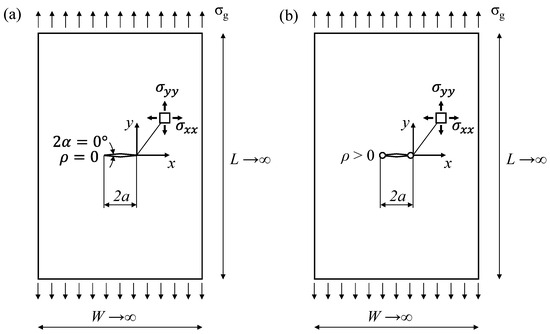
Figure 1.
Schematic of a central crack under tension in an infinite plate with details on the local stress field components: (a) before and (b) after the introduction of the stop-holes at the previous crack tips.
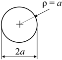
Linear elastic Finite Element Analyses were carried out to study the stress fields of three different notch geometries, whose parameters are summarised in Table 1. The first one is a crack with a single stop-hole (column 1 of Table 1), where each crack tip is blunted by adding a circular notch with radius, ρ, while keeping constant the overall dimension, 2a, of the notch. In this case, ρ and a are limited to ρ/a ≤ 1, since for greater ρ/a, the overall dimension, 2a, of the notch would be greater than the initial one. Noteworthily, in practice, the stop-holes are typically centred on the crack tip both for practical reasons and to ensure that the crack tip is effectively blunted. As a result, the final notch is inevitably larger (has a greater 2a) than the initial one.

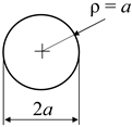
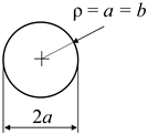
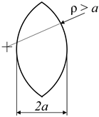
Table 1.
Notch geometries.
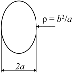
The second geometry is that of U-shaped rounded notch (column 2 of Table 1), whose stress field is known in approximate closed form for ρ/a << 1 [6,7]. Also, this geometry can only be defined for values of ρ/a ≤ 1, since it collapses into a circular notch for ρ/a = 1. However, the analysis was extended to values of ρ/a > 1 by considering a modified notch geometry, as shown in Table 1. The third and last geometry is that of an elliptical notch (column 3 of Table 1), whose stress field is fully known thanks to Inglis’ work [8]. For elliptical notches, the fillet radius, ρ, at the bisector of the notch is related to the dimensions of the ellipse’s semi-axes, a and b, by the relation ρ = b2/a.
Different values of ρ/a were considered, ranging from less than 10−2 up to 103, while keeping constant the notch depth a = 5 mm. The ratio between the notch size, a, and the plate width, W, was chosen equal to 2a/W = 0.001 (see Figure 1), to ensure the condition of an infinite plate. FEA were performed using ANSYS® Workbench, where the 2D geometries were modelled by exploiting double symmetry. The chosen material was a structural steel, with an elastic modulus E = 206,000 MPa and a Poisson’s ratio ν = 0.3. The different geometries were discretized using a free mesh pattern of second-order plane elements (PLANE 183 in ANSYS®), with progressively refined mesh density near the notch tip. The mesh size was appropriately defined through convergence analyses.
The results are shown in Figure 2, which illustrates how the opening stress component, σyy, varies along the notch bisector x line (see Figure 1). For comparison, Figure 2 also includes the singular stress field of the sharp crack (with ρ = 0), depicted by the continuous black line.
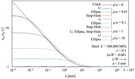
Figure 2.
Opening stress, σyy, as a function of the position, x, along the bisector line for different notch geometries (stop-hole red lines, U-notches dark blue lines, and Elliptical notches dark blue) and ρ/a.
Figure 2 shows that the notch type (stop-hole, U-notch, or elliptical notch—Table 1) has a negligible effect on the opening stress field along the bisector line for a given ρ/a. Nevertheless, slight differences become noticeable when analysing the stress field nearby the elastic peak stress σρ (as x → 0). Specifically, for ρ/a < 1, the elliptical notch (light blue lines in Figure 2) has a slightly lower elastic peak stress, σρ, compared to a U-notch or a stop-hole, which behaves the same (dark blue and red lines in Figure 2). Conversely, for ρ/a > 1, the elliptical notch produces a slightly higher σρ. These differences are clearly highlighted in Figure 3, which shows the values of the Stress Concentration Factor Kt = σρ/σg for all the analysed notch geometries as a function of ρ/a.
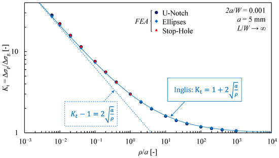
Figure 3.
Stress concentration factor, Kt, as a function of ρ/a for different notch geometries.
In this figure, numerical results (coloured markers in Figure 3) are compared with the Kt, analytically calculated by using the well-known Inglis equation [8], (solid light blue line in Figure 3). Additionally, as ρ/a → 0, Kt asymptotically approaches the line described by the relation (dashed light blue line in Figure 3). Finally, from Figure 2 and Figure 3 it becomes clear that stop-hole geometry can be treated exactly like it were an elliptical notch.
3. Estimating the Fatigue Limit of Cracked Components with Stop-Holes
The research on the fatigue limit of notched components has a long history, dating back to the early works of Frost et al. [9] and Smith and Miller [10], who were the first to observe and highlight a clear distinction in fatigue behaviour between blunt and sharp notches. They proposed the well-known Frost–Miller diagram, which provides the fatigue limit of a notched component as a function of the Stress Concentration Factor, Kt. They also identified a critical value of Kt*, above which the dependence on ρ disappears, as the notch behaves like it is sharp (ρ = 0).
Years later, Atzori and Lazzarin [2,11] suggested evaluating notch sensitivity by correlating the fatigue limit with the absolute size of the notch, a, while keeping constant the notch acuity, a/ρ, i.e., by keeping constant the stress concentration factor, Kt. In conducting so, they proposed a generalisation of the Kitagawa–Takahashi diagram [12], which is also valid for rounded notches. This approach was later widely validated with experimental data and extended to the case of rounded open notches (2α ≥ 0, ρ ≥ 0) [13,14].
A schematic of the Atzori–Lazzarin–Meneghetti (ALM) diagram is shown in Figure 4 for the case of notches having a null opening angle (2α = 0). The key advantage of this diagram is its ability to simultaneously describe notch sensitivity and defect sensitivity, by considering both the size effect (a) and the notch acuity effect (a/ρ). Specifically, it identifies three distinct regions (see Figure 4): one of complete notch insensitivity, with a < a0, where a0 is the length parameter, first proposed by El Haddad et al. [15]; a second region of complete insensitivity to the notch tip fillet radius for a0 < a < a*; and a region of full notch sensitivity for a > a*. In particular, for a < a0, the notches/defects are so small that they do not affect the fatigue limit of the component Δσg,th, which equals the fatigue limit of the defect-free plain material Δσ0. Conversely, for a0 < a < a*, the notch is so sharp (i.e., the fillet radius ρ is so small) that it behaves as a crack of the same size. In this case, the fatigue limit of the notched component is governed by Linear Elastic Fracture Mechanics (LEFM), and the fatigue limit knock-down factor Kf = Δσ0/Δσg,th is given as follows:
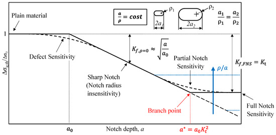
Figure 4.
Atzori–Lazzarin–Meneghetti diagram applied to notches having constant Kt.
Note that Equation (1) is the approximate form of a more accurate expression (), which accounts for the real shape of the ALM diagram in the short crack regime (see dashed line on the defects sensitivity region in Figure 4) [11,15].
Finally, for a > a*, there is Full Notch Sensitivity (FNS), and classical notch mechanics apply, where Kf,FNS = Kt.
Atzori and Lazzarin [2,11] observed that, for a given material, the branch point depends on the notch acuity and can be described by the following relation:
The same authors observed that, under the assumption of a high Kt, it is possible to define a critical fillet radius, ρ*, beyond which the full notch sensitivity is achieved [2]:
Despite the validity of this diagram, its application to the specific case of a stop-hole geometry may not be straightforward due to the implicit dependence on the fillet radius ρ. Figure 5 presents a different diagram, inspired by the one proposed by Zappalorto [16] for evaluating notch sensitivity under static loadings, which is better suited to illustrate the effect of ρ on the fatigue limit of a notched component, Δσg,th. Such diagram describes the fatigue limit as a function of ρ, while keeping the notch depth, a, constant (Figure 5). The new diagram distinguishes between two different regions: one of complete insensitivity to the notch tip radius when ρ < ρ*, and one of full notch sensitivity (FNS) for ρ > ρ*. Specifically, for ρ < ρ*, the fillet radius, ρ, is so small that the notch behaves as if it is sharp (ρ = 0 → ), while for ρ > ρ*, FNS and classical notch mechanics apply (Kf,FNS = Kt). In the FNS region (on the right side of the diagram in Figure 5), the value of Kt can be represented by a line with a slope of 0.5 in a double-logarithmic plot. This line has been dashed because it represents only a simplifying hypothesis valid only for sharp notches, as will be better explained later. In this case, for ρ > 4a, the notch is so blunt (with Kt being small) that it approaches the case of a smooth specimen without notches (Kf,FNS = Kt → 1). Additionally, as the notch size, a, increases (see the dashed blue lines in Figure 5), the diagram shifts downward, maintaining the fillet radius value at the branch point (ρ* is a material property, independent of absolute dimensions), but delaying the intersection with the smooth specimen asymptote.
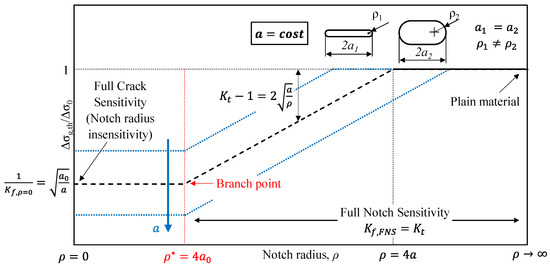
Figure 5.
Normalised fatigue limit of the notched component, Δσg,th/Δσ0, as a function of the notch tip radius, ρ.
Going back to the considerations on stop-hole, this diagram allows for some simple yet effective observations. The first is that, for a given material (i.e., for a specific value a0), the introduction of a stop-hole is effective only when the drilled hole has a radius ρ > ρ*. Viewed from another perspective, this means that the introduction of a stop-hole is more advantageous the smaller the value of a0, which generally corresponds to higher strength in case of steels [13,14]. Furthermore, the diagram shows that, for a given material, the potential improvement in fatigue resistance after introducing a stop-hole is greater the larger the absolute size of the crack, a. This implies that for small cracks, the introduction of a stop-hole may not provide sufficient improvement to justify using this technique. From another point of view, it means that the shape, ρ/a, of isolated defects (or small notches) does not significantly influence their fatigue limit shape, and, to a first approximation, they behave as sharp notches (ρ = 0).
To apply and graphically represents Inglis’ expression [8] instead of its approximate version, we propose the diagram in Figure 6, which plots the normalised fatigue limit, Δσg,th/Δσ0, versus the inverse of the notch acuity, ρ/a. This diagram highlights the significant influence of using the right expression for Kf,FNS = Kt (solid black curve in Figure 6), compared to the approximate expression, Kf,FNS ≈ Kt − 1 (dashed black curve in Figure 6), which is valid only for ρ/a → 0. One of the main differences is that the approximate relation leads to unconservative estimates, particularly when the value of a is small, i.e., in the defect region. A second difference is related to the actual branch point, since its position is described by a new parameter ρ**, which is not a material property as for ρ* = 4a0. The value of ρ** can be easily estimated in an approximate form as follows:
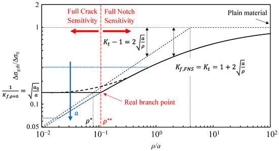
Figure 6.
Normalised fatigue limit of the notched component, Δσg,th/Δσ0, as a function of ρ/a.
Or, more accurately, ρ** can be expressed as follows:
If the El Haddad correction for short cracks [15] is considered.
4. Conclusions
This work investigates the effect of introducing a non-zero fillet radius, ρ, at the crack tip of cracked components under uniaxial fatigue loading. Specifically, it introduces and presents a new diagram, which explicitly highlights the influence of the notch tip radius on the fatigue limit of such components. A significant aspect of this diagram is the possibility to clearly identify when the adoption of a fillet radius ρ > 0 at the notch tip effectively results into an increased fatigue limit. More in detail, it highlights the value of a critical fillet radius, ρ**, below which the dependence on ρ disappears, as the notch behaves like it is sharp (ρ = 0). Conversely, for ρ > ρ**, the fatigue limit of the notched component is sensitive to the size of the notch tip radius, ρ. Interestingly, the concept of a critical radius, ρ*, was previously introduced to identify the so-called branch point, differentiating between sharp and blunt notch behaviour. However, the present manuscript shows that this value depends on the absolute size of the notch and is, therefore, not a material property.
A practical application of the proposed diagram is the “stop-hole” technique, where a hole is drilled at the crack tip of a cracked component. The fillet radius introduced by the stop-hole reduces the intensity of the local stress field at the crack tip and can significantly improve the fatigue resistance of the component, provided the adopted radius, ρ, is sufficiently large. In this regard, the new diagram enables precise determination of the conditions and extent to which the introduction of a stop-hole can effectively enhance the fatigue resistance of cracked components. More in detail, it shows that, typically, the introduction of a stop-hole is more effective the smaller the value of a0, i.e., El Haddad’s length parameter, which generally corresponds to higher strength in case of steels. Secondly, it shows that, for a given material, the potential improvement in fatigue resistance after introducing a stop-hole is greater the larger the absolute size of the crack. This implies that for small cracks, the introduction of a stop-hole may not provide sufficient improvement to justify using this technique.
Author Contributions
Conceptualization, B.A.; Data curation, L.V.; Formal analysis, L.V.; Investigation, L.V.; Methodology, B.A., L.V. and G.M.; Project administration, B.A. and G.M.; Resources, G.M.; Software, L.V.; Supervision, B.A. and G.M.; Validation, L.V.; Visualisation, L.V.; Writing—original draft preparation, L.V.; Writing—review and editing, B.A., L.V. and G.M. All authors have read and agreed to the published version of the manuscript.
Funding
This research received no external funding.
Institutional Review Board Statement
Not applicable.
Informed Consent Statement
Informed consent was obtained from all subjects involved in the study.
Data Availability Statement
The original contributions presented in the study are included in the article; further inquiries can be directed to the corresponding author.
Conflicts of Interest
The authors declare no conflicts of interest.
References
- Radaj, D.; Sonsino, C.M.; Fricke, W. Fatigue Assessment of Welded Joints by Local Approaches, 2nd ed.; Woodhead Publishing: Cambridge, UK, 2006. [Google Scholar]
- Atzori, B.; Lazzarin, P. Notch Sensitivity and Defect Sensitivity under Fatigue Loading: Two Sides of the Same Medal. Int. J. Fract. 2001, 107, L3–L8. [Google Scholar] [CrossRef]
- Domazet, Ž. Comparison of Fatigue Crack Retardation Methods. Eng. Fail. Anal. 1996, 3, 137–147. [Google Scholar] [CrossRef]
- Goto, M.; Miyagawa, H.; Nisitani, H. Crack Growth Arresting Property of a Hole and Brinell-Type Dimple. Fatigue Fract. Eng. Mater. Struct. 1996, 19, 39–49. [Google Scholar] [CrossRef]
- Jiang, X.; Lv, Z.; Qiang, X.; Zhang, J. Improvement of Stop-Hole Method on Fatigue-Cracked Steel Plates by Using High-Strength Bolts and CFRP Strips. Adv. Civ. Eng. 2021, 2021, 6632212. [Google Scholar] [CrossRef]
- Filippi, S.; Lazzarin, P.; Tovo, R. Developments of Some Explicit Formulas Useful to Describe Elastic Stress Fields Ahead of Notches in Plates. Int. J. Solids Struct. 2002, 39, 4543–4565. [Google Scholar] [CrossRef]
- Lazzarin, P.; Filippi, S. A Generalized Stress Intensity Factor to Be Applied to Rounded V-Shaped Notches. Int. J. Solids Struct. 2006, 43, 2461–2478. [Google Scholar] [CrossRef]
- Inglis, C.E. Stresses in a Plate Due to the Presence of Cracks and Sharp Corners. Trans. Inst. Naval. Archit. 1913, 55, 219–241. [Google Scholar]
- Frost, N.E.; Marsh, K.J.; Pook, L.P. Metal Fatigue; Oxford University Press: Oxford, UK, 1974. [Google Scholar]
- Smith, R.A.; Miller, K.J. Prediction of Fatigue Regimes in Notched Components. Int. J. Mech. Sci. 1978, 20, 201–206. [Google Scholar] [CrossRef]
- Atzori, B.; Lazzarin, P. A Three-Dimensional Graphical Aid to Analyze Fatigue Crack Nucleation and Propagation Phases under Fatigue Limit Conditions. Int. J. Fract. 2002, 118, 271–284. [Google Scholar] [CrossRef]
- Kitagawa, H.; Takahashi, S. Applicability of Fracture Mechanics to Very Small Cracks or the Cracks in the Early Stage. In Proceedings of the Second International Conference on Mechanical Behaviour of Materials, American Society for Metals, Metals Park, OH, USA, 16–20 August 1976; pp. 627–631. [Google Scholar]
- Atzori, B.; Lazzarin, P.; Meneghetti, G. A Unified Treatment of the Mode I Fatigue Limit of Components Containing Notches or Defects. Int. J. Fract. 2005, 133, 61–87. [Google Scholar] [CrossRef]
- Atzori, B.; Lazzarin, P.; Meneghetti, G. Fracture Mechanics and Notch Sensitivity. Fatigue Fract. Eng. Mater. Struct. 2003, 26, 257–267. [Google Scholar] [CrossRef]
- El Haddad, M.H.; Topper, T.H.; Smith, K.N. Prediction of Non Propagating Cracks. Eng. Fract. Mech. 1979, 11, 573–584. [Google Scholar]
- Zappalorto, M. Static Notch Sensitivity in Orthotropic Materials and Composites. Eur. J. Mech. A/Solids 2021, 85, 104094. [Google Scholar] [CrossRef]
Disclaimer/Publisher’s Note: The statements, opinions and data contained in all publications are solely those of the individual author(s) and contributor(s) and not of MDPI and/or the editor(s). MDPI and/or the editor(s) disclaim responsibility for any injury to people or property resulting from any ideas, methods, instructions or products referred to in the content. |
© 2025 by the authors. Licensee MDPI, Basel, Switzerland. This article is an open access article distributed under the terms and conditions of the Creative Commons Attribution (CC BY) license (https://creativecommons.org/licenses/by/4.0/).


