1. Introduction
The role of fiber-reinforced polymer (FRP) composites in lightweight structural applications in the automotive and aerospace sectors has grown tremendously over the past few decades. Despite their high strength-to-weight ratio, tailorable structural properties, and other attractive attributes, they are characterized by intrinsically poor interlaminar properties. This makes them susceptible to delamination and crack growth when subjected to off-axis loading to their laminate direction, such as compressive or flexural loads [
1]. Even small-scale damages in the FRP composites can coalesce under subsequent off-axis loading. This results in the practice of using high safety factors to ensure their reliable service use.
While most of the academia and industrial sectors are seeking out Non-Destructive Evaluation (NDE) tools to identify small-scale damage at an early stage, some others are progressing towards developing healable FRP composites [
2,
3]. Although the self-healing capability of bulk polymer systems has been studied in the literature, their applications in FRP composites and their potential use in the industrial sector are scarce [
1].
The intrinsic self-healing capability of the polymer matrices has been studied extensively in the literature. This self-healing method relies on the physical or chemical interaction and functionalities of the polymer matrix itself [
4,
5,
6,
7,
8]. For instance, covalently bonded structures such as disulfide groups are introduced in the epoxy matrix systems. At temperatures above 120 °C, reactions such as Dies–Alder activates, which causes the monomer linkages in the epoxy system to disconnect, flow to the damaged area, and reconnect upon cooling. Similarly, other systems such as polyetherimide, disulfide-based, multiphase, and supramolecular elastomers can be activated upon heating the polymer system at high temperatures to activate healing [
4,
5,
6]. In some cases, thermoplastics are blended into the thermoset systems, which flow upon heating and heal the damaged area [
9].
However, most of these self-healing systems either require introducing high brittleness into the polymer system, thereby compromising its mechanical properties, or exhibit poor thermal resistance after healing. To achieve a high modulus retention after healing, the polymer must be heated to a very high temperature, resulting in undesirable mechanical, thermal, or thermo-mechanical properties [
1,
9].
Recently, a self-healing polymer system based on an organic–inorganic disulfide was introduced. This reactive agent is compatible with epoxy thermosets and requires moderate temperatures (less than 100 °C) to activate the healing mechanisms. Recent studies explored the mechanical property retention of Glass-FRP (GFRP) and Carbon-FRP (CFRP) composites [
9,
10,
11]. Some researchers have introduced novel methods to quantify the self-healing capability of these composites by testing them mechanically after several damaging–healing cycles.
Several NDE tools are available to identify the damage evolution in FRP composites, such as ultrasonic (US) testing, infrared thermography, and tomography. In theory, most of these systems can be effectively used in evaluating the healing characteristics of the composites. However, most of these NDE tools can be used only when the composites are not under service conditions. This essentially limits the autonomy of using self-healing composites in the industrial sector and other structural applications [
12].
Acousto-Ultrasonic (AU) testing is an NDE tool that integrates the diagnostic capabilities of US testing and in-service monitoring capabilities of the acoustic emission (AE) technique. In this method, artificial stress waves are simulated through a specimen or structure and acquired using a piezoelectric sensor after propagating them to a predefined distance. By analyzing the propagation characteristics of the stress waves in their time or frequency domain, the integrity of the propagation medium can be evaluated [
13,
14].
In this research work, the healing capability of a novel self-healing composite system is studied using the AU technique. To this end, self-healing CFRP specimens were first damaged using an off-axis loading. The mechanical performance of these composites was studied under virgin, damaged, and damaged–healed conditions. The AU technique was used in each stage to quantify the damage level and healing capabilities of the composites.
2. Experimental Section
2.1. Materials
CFRP composite laminates were prepared using a commercially available healable thermoset resin system supplied by CompPair Technologies Ltd. HealTech
TM (Renens, Switzerland). Three different types of healable resin systems, pre-impregnated with high-strength carbon fibers T300 TW200, T700 TW415, and T700 UD200, were used to prepare the composites (TW—twill weave; UD—unidirectional fiber configurations). Layup configurations of the composites tested in this study are presented in
Table 1.
For the off-axis loading, standard flexural test specimens with rectangular cross-sections were prepared following the recommendations of ASTM D790 [
15]. All the specimens have the nominal dimensions of 200 mm × 20 mm × 3 mm.
Healing of the Composites
Healing in the composite specimens used in this study was activated using the following procedure. First, the specimens were placed in an oven, which was preheated to 150 °C. The specimens were then kept in the oven until their surface temperature reached 100 °C (a thermocouple is used to monitor the surface temperature). Once the surface temperature reached 100 °C, healing was activated for 15 min. Then, the specimens were left at room temperature for 48 h for the healing process to complete.
2.2. Test Scheme to Evaluate the Self-Healing Capability of the Composites
To evaluate the healing capabilities of the self-healing composites, both their mechanical and acoustic wave propagation behaviors at various conditions were studied. The test specimens were evaluated in their virgin, damaged, and damaged–healed conditions.
To study the mechanical behavior of the specimens, 3-point bending flexural tests were carried out at all three conditions. To artificially create matrix damage in the specimens, 10% of the failure flexural load was applied to the virgin specimens.
As mentioned earlier, the AU test method was used to evaluate the acoustic wave propagation behavior. While the mechanical tests were carried out under 3 different test conditions, the AU tests were carried out under 4 different specimen conditions. In addition to testing, such as virgin, damaged, and damaged–healed, the specimens were tested using AU when they were partially healed. The test scheme followed in this research work is summarized in
Figure 1.
In addition, a set of preliminary AU tests were carried out on the self-healing laminates to evaluate the most reliable wave features that can be used in the signal data analysis. More details about the preliminary tests are presented in the subsequent sections.
2.3. Three-Point Bending Tests
As mentioned earlier, the 3-point bending tests were carried out in accordance with the ASTM D790 standard in an INSTRON servo-hydraulic test machine with a maximum load capacity of 100 kN. The tests were carried out in a displacement-controlled mode at a rate of 8 mm/min. The mechanical properties were evaluated in terms of flexural strength, which was calculated upon the maximum load carried by the test specimens before failure.
For creating an off-axis load matrix damage, the same test procedure was followed. The specimens were loaded at the same crosshead displacement rate of 8 mm/min but stopped when the load reached 10% of the maximum flexural load carried by the virgin specimens.
The damaged and damaged–healed specimens were also then loaded up to failure under the same test conditions, and their flexural strengths were calculated.
2.4. Acousto-Ultrasonic Testing
In the AU tests, stress waves were simulated through the specimens by spiking a piezoelectric crystal with a burst of 24 V and a pulse width of 5 μs. A total of 5 stress wave signals were simulated through the specimens at an interval of 100 ms to avoid the acquisition of reverberations.
The stress waves were propagated for a distance of 180 mm longitudinally along the surface of the specimen and transversally through the thickness. The propagated signals were acquired using a piezoelectric sensor, PICO, which has an operating frequency of 200 kHz to 750 kHz and resonant frequencies at 250 kHz and 550 kHz. The signals were acquired at a sample rate of 2 MHz. The propagated signals were then studied in their frequency domain using fast Fourier transform (FFT) to understand the interlaminar properties of the propagating medium.
As mentioned in
Section 2.2., the AU tests were carried out under virgin and damaged conditions. The same test procedure was followed 2 h after the activation of the healing process (partially healed conditions) and 48 h after healing (fully healed conditions).
3. Preliminary Acousto-Ultrasonic Tests
Since the composites tested in the study are novel, there is a lack of information on the frequency characteristics of the acoustic waves propagating in them. Moreover, the test/specimen conditions, such as the contact pressure of the sensor and the layup configuration, may influence the wave propagation characteristics. Therefore, it is essential to identify the most appropriate features that can be used in the AU tests. For this reason, preliminary AU tests were carried out on the self-healing CFRP composite laminate. Details about the specimen are presented in
Table 2. To avoid the acquisition of boundary edge reverberations, the laminates tested in this study have a much larger width compared to the 3-point bending test specimens.
The preliminary tests were carried out under the features of propagating stress waves due to the contact pressure of the sensor and the propagation direction with respect to the fiber direction.
For the first condition, the AU tests were carried out by placing the receiving piezoelectric transducer at four different contact pressures, which are given in
Table 3. The contact pressures are the measure of the calibrated weight placed over the sensor per its surface area. Necessary actions were taken to ensure that the sensors were held firmly to the surface at all contact pressures. The stress waves, under the same conditions in
Section 2.4., were propagated for a distance of 80 mm longitudinally.
Figure 2 shows the frequency spectrum of the pulsed and received signals.
As seen in
Figure 2, the pulsed signal has a peak frequency of 437.5 kHz, which is shifted to 322 kHz at the receiver end. During wave propagation, both attenuation and dispersions occur, which depends on the propagating medium. Particularly in FRP composites, the dispersion is higher due to the complex propagation medium and internal lamina geometries.
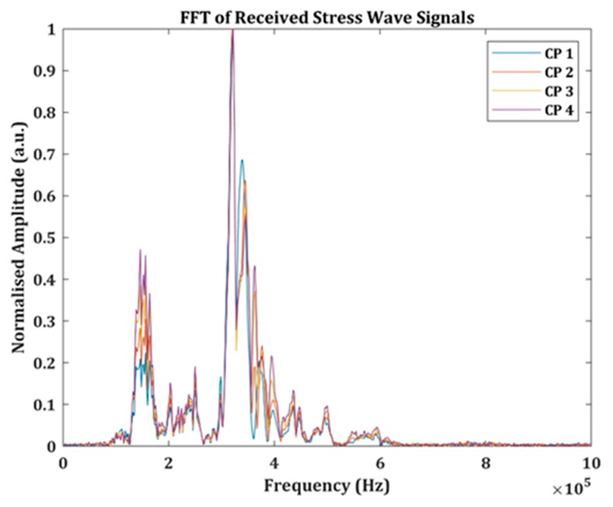
The frequency spectrum of the propagated signals under different contact pressure conditions is presented in
Figure 3. Upon looking at the results in
Table 3 and
Figure 3, one can understand that the peak frequency and the frequency centroid are not affected by the contact pressure under which the sensor is held. The peak amplitudes vary significantly with the different contact pressures, while the signal power has a more or less linear relationship with them. Therefore, in the further AU signal data analysis, the frequency features were considered.
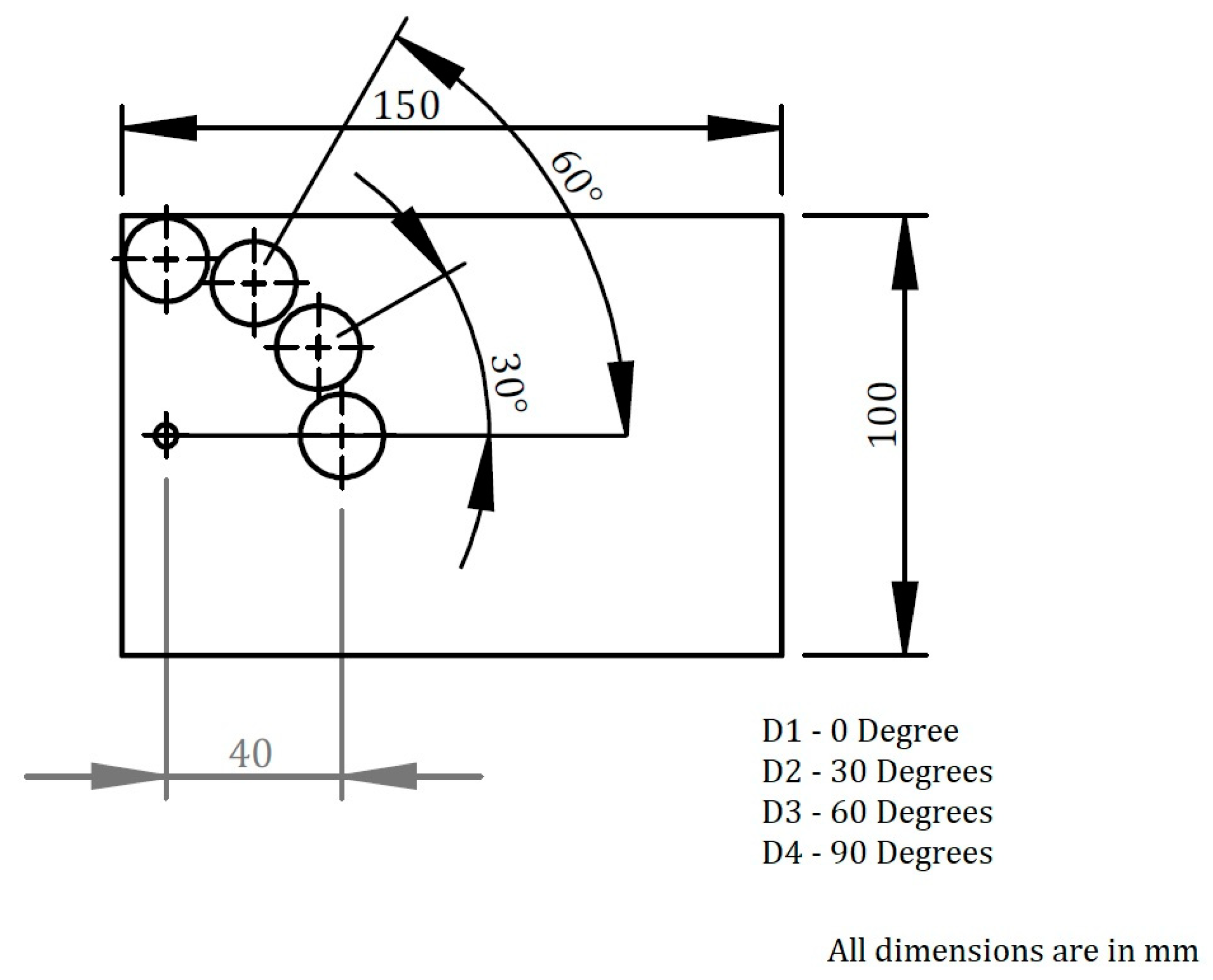
For the second test condition, the piezoelectric sensor was placed at four different angles with respect to the longitudinal axis of the pulser. A schematic representation of the test condition with respect to the propagation direction is presented in
Figure 4.
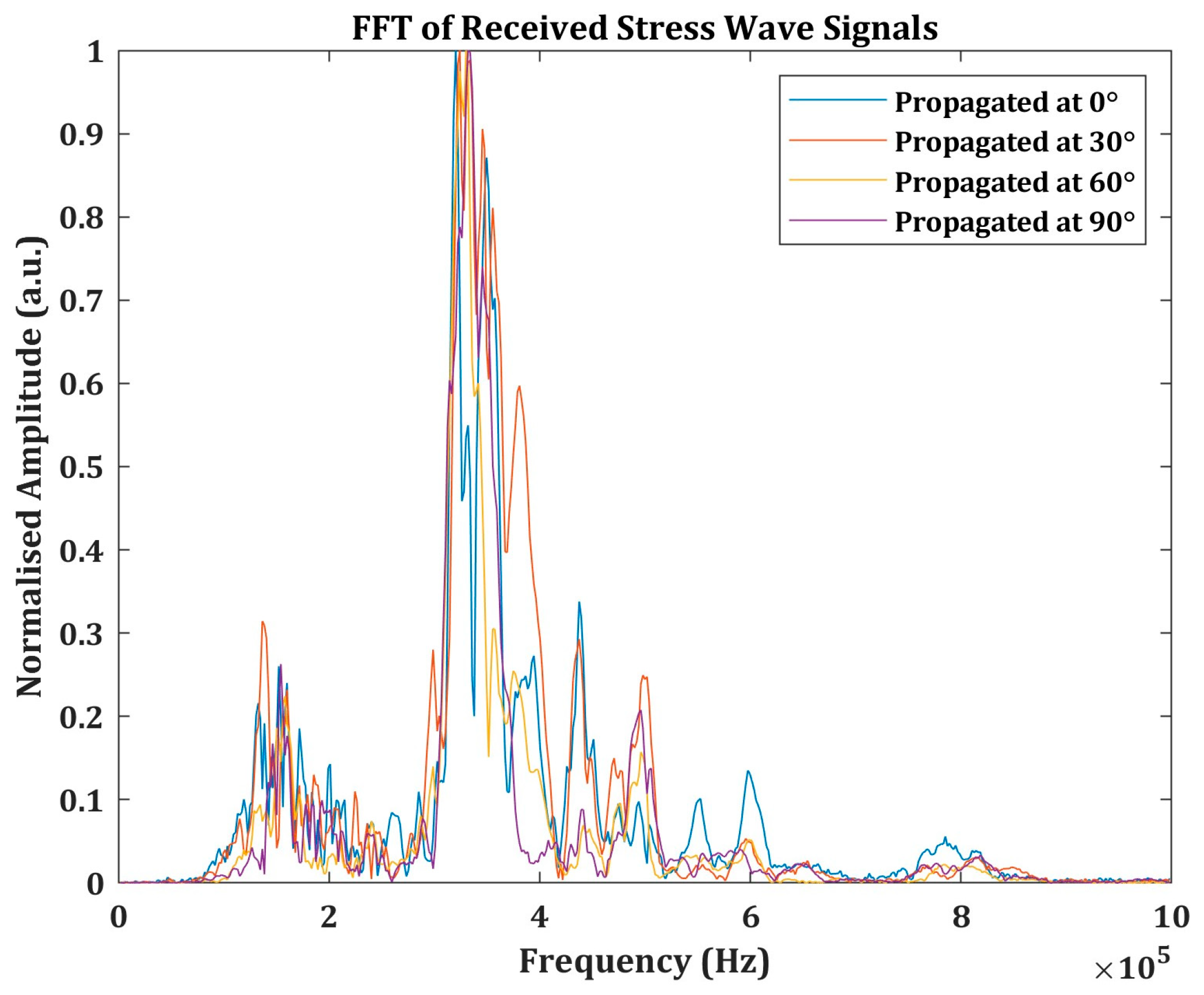
In these test conditions, the sensors were held at a constant contact pressure of 5.30 kPa for all the propagation directions. Stress waves, similar to the previous pulsing voltage and duration, were propagated for 40 mm. The frequency characteristics of the propagated signals in the four different directions are presented in
Figure 5.
The wave features are presented in
Table 4 for comparison. As seen from
Figure 5 and
Table 4, there is a large variation in the peak amplitude despite the same contact pressure. This could be correlated with the results in
Table 3, where the stress waves are propagated for 80 mm. The shorter propagation distance resulted in lower attenuation, which resulted in a high peak amplitude and signal power compared to the previous test conditions.
While looking at the frequency parameters, the peak frequency and frequency centroids are both affected by the propagation direction. At the 30° and 60° propagation directions, the frequency shifted from 320 kHz to 324 kHz and 330 kHz, respectively. The difference between 60° and 90° is not quite large, as the shift is only 2 Hz. Nevertheless, there is a larger difference in the frequency centroid, comparatively. This signifies, again, that the frequency parameters are more appropriate and reliable for analyzing the propagating stress waves in the AU tests.
4. Experimental Results and Discussion
The AU tests and the 3-point bending tests were carried out, as mentioned in
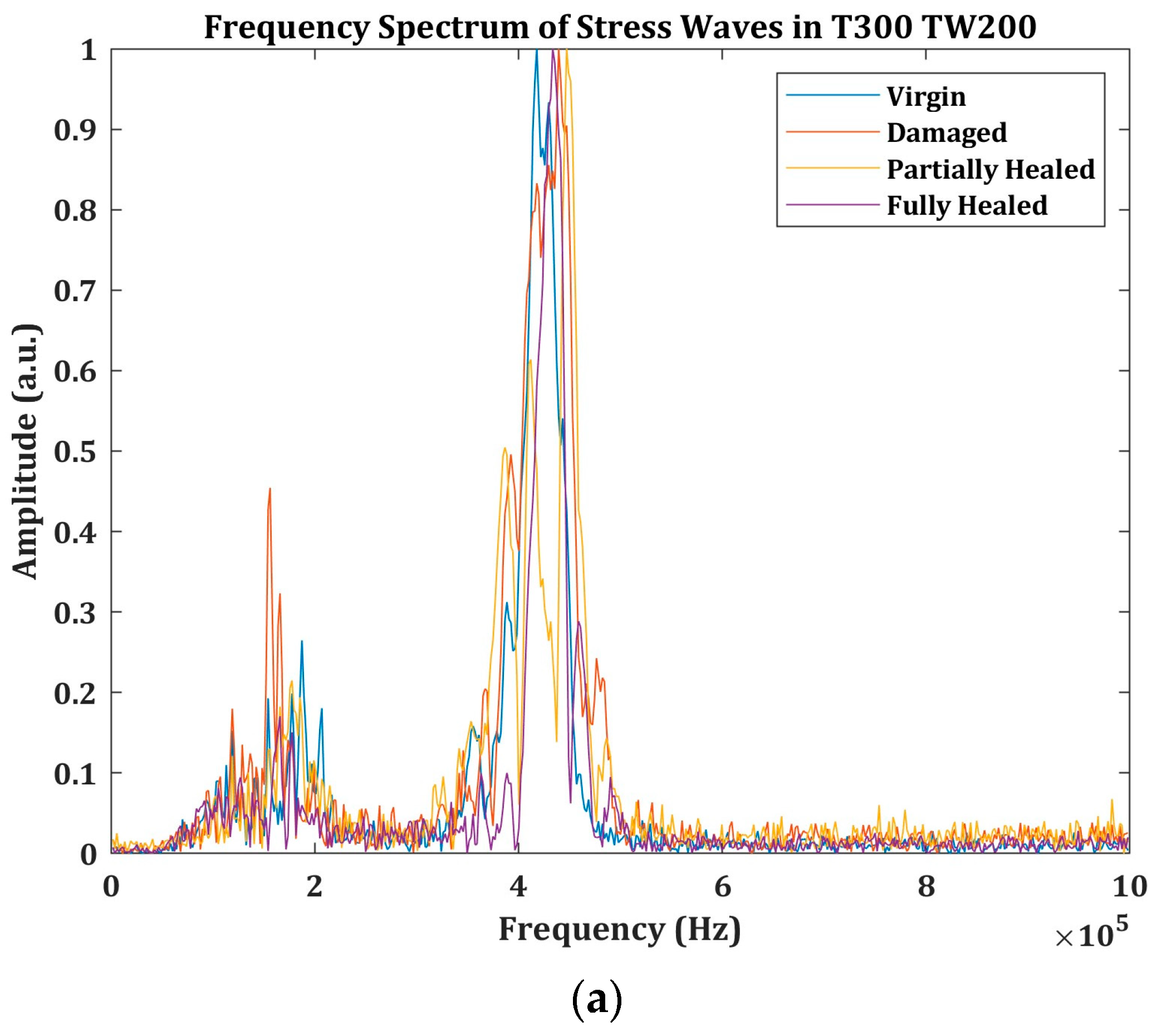
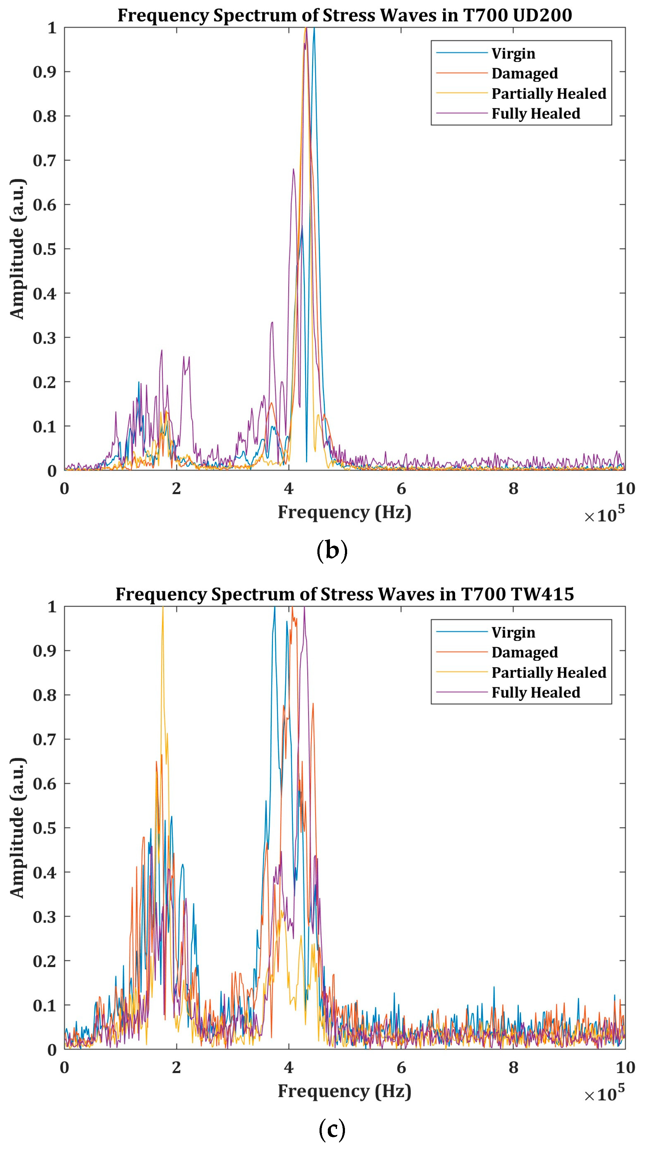
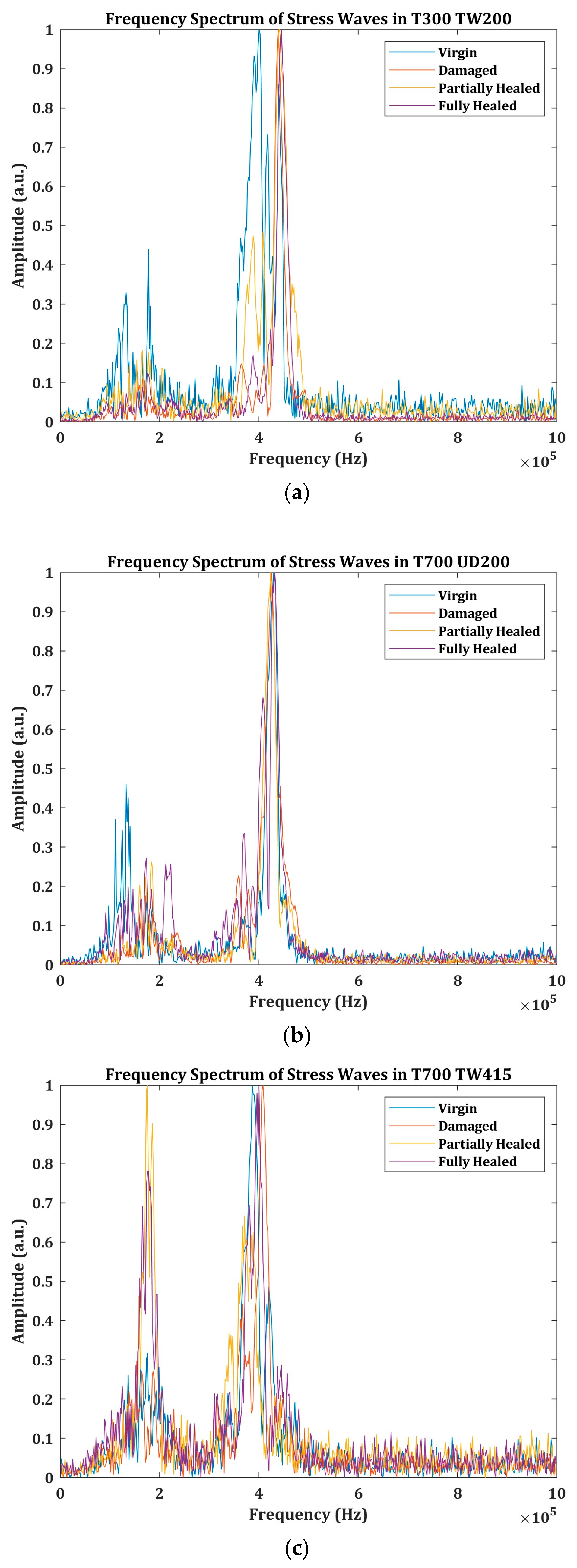
Section 2.2. The frequency spectrum of the stress wave signals propagated through the virgin, damaged, partially healed, and fully healed specimens are presented in this section. The stress waves propagated in the longitudinal direction are presented in
Figure 6, while the ones propagated through thickness are presented in
Figure 7.
In the longitudinal propagation, the shift in the frequency spectrum can be seen in the stress waves propagated through all three specimens in
Figure 6. Although the majority of the energy of the propagated stress waves under all four conditions of the test specimens appears to lie in the same frequency band, the differences in peak frequencies and other frequency spreads are different. Particularly, the differences in the frequency spread of T700 TW415 are quite high compared to the other two specimens. This indicates that the damaged, partially healed, and fully healed conditions of the test specimens have much different interlaminar properties (in the propagation direction) than the virgin specimens.
Frequency spectrums of the stress waves propagated through the thickness of the specimens are presented in
Figure 7. In this case, there is very little shift in the frequencies in T700 UD200. The stress waves in the damaged and healed conditions of T300 TW200, on the other hand, are considerably different from the virgin conditions, however, not among themselves. Similar to the longitudinally propagated waves, the stress waves in T700 TW415 also show a considerable amount of change in their frequency spectrum.
The differences in these frequencies can be attributed to the lamina layup configurations and the interlaminar properties of the composites [
13,
14].
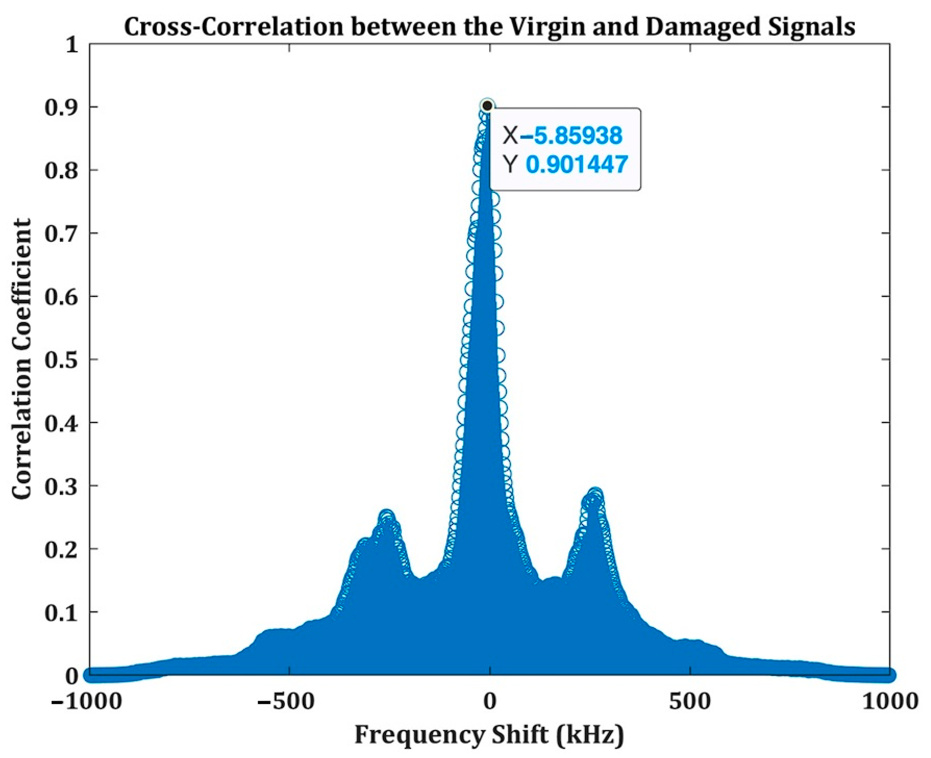
To quantify the differences in the frequency spectrum and to explicitly associate these differences with the different conditions of the test specimens, a cross-correlation analysis was used. In this analysis, the frequencies of the stress waves under damaged, partially healed, and fully healed conditions were correlated with the stress waves in the virgin signal. A sample of this cross-correlation result is presented in
Figure 8.
The cross-correlation in the given example shows that there is a high correlation between the signals with the frequency shift of −5.86 kHz. Based on this, the different conditions of the test specimens relative to their virgin conditions can be identified. The analysis was carried out for all the signals propagated during the AU tests in all the test specimens. The cross-correlation results are presented in
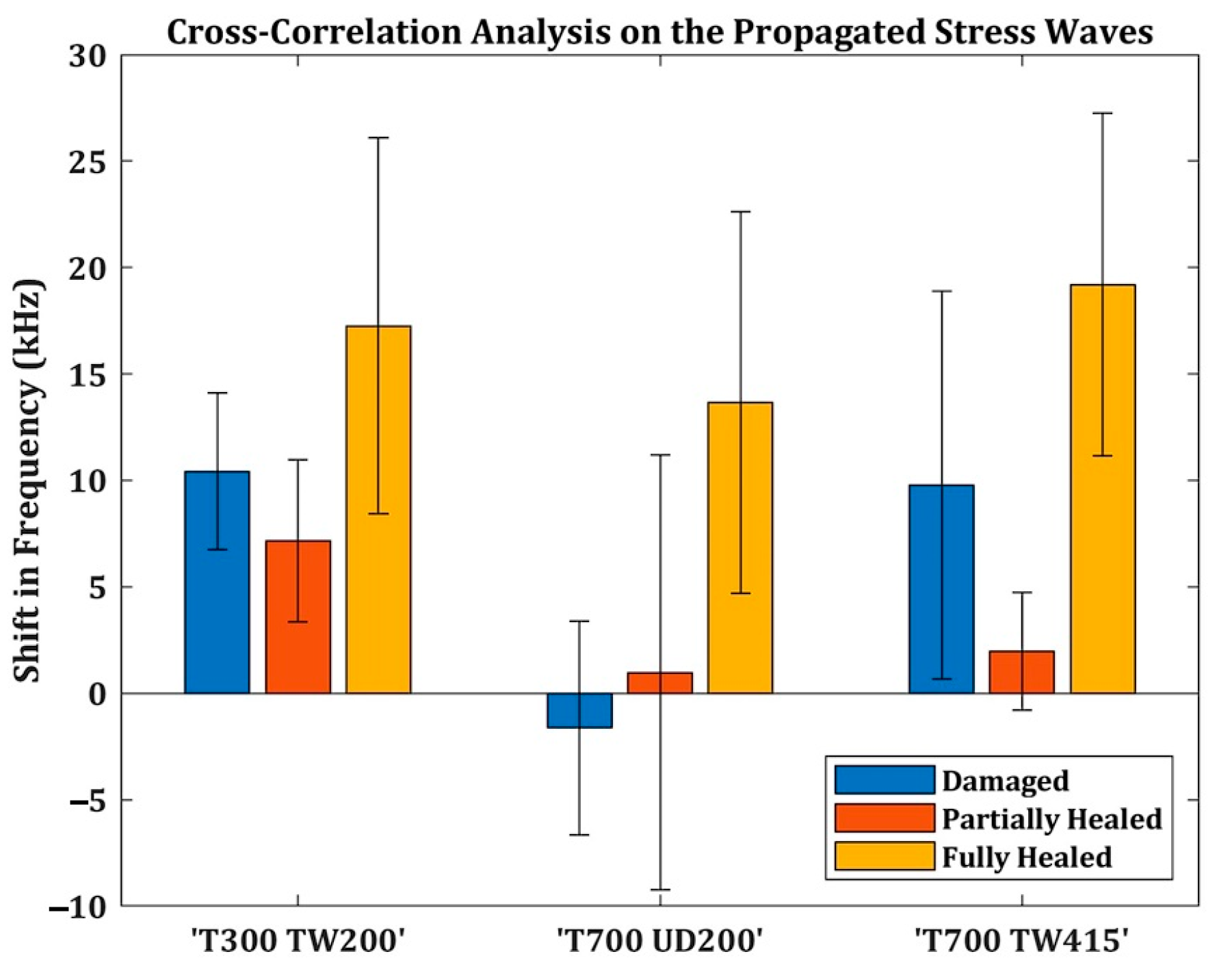
Figure 9.
In
Figure 9, the correlation between the virgin specimen and the damaged specimens showed that there is a clear shift in the frequency spectrum, which accounted for 10.42 ± 3.68 kHz in T300 TW200, −1.6 ± 5.01 kHz in T700 UD200, and 9.77 ± 9.11 kHz in T300 TW415 specimens. The negative shift in T700 UD200 could be due to the unidirectional fiber orientation in the lamina of this specimen group. Some researchers have evidently proved that the fiber direction plays a crucial role in the propagation of acoustic stress waves [
16]. Nevertheless, in all three groups, the stress waves propagated in the damaged specimen show a clear difference from the virgin specimen.
In the partially healed specimens however, there is a very small amount of frequency shift with respect to the virgin specimen, particularly in the T700 UD200 and T300 TW415 specimens. It was shown by some researchers that the curing temperature and the viscoelastic conditions of the prepreg during curing could attenuate and disperse the propagation of stress waves [
17]. As explained in
Section 1., the self-healing in these composites is activated by heating, which makes the crosslinks in the polymer chain break, which results in them flowing and filling the damaged areas [
1,
9]. This viscoelastic change in the polymer system probably resulted in affecting the frequencies of the stress waves in partially healed conditions.
Under fully healed conditions, the stress waves show larger frequency shifts to the virgin conditions. In T300 TW200, the frequency shifted to 17.25 ± 8.8 kHz, in T700 UD200, the frequency shifted to 13.67 ± 8.96 kHz, and in T700 TW415, it shifted to 19.20 ± 8.05 kHz. This shows that the interlaminar properties of the specimens post-healing have changed entirely.
Now, to understand the healing efficiency of these specimens, their flexural strengths are evaluated using 3-point bending tests, as explained in
Section 2.3. The results are presented in
Figure 10.
The results show that, except for the T700 TW415 specimens, the other specimens did not manage to retain their flexural strength after the healing process. Although these self-healing composites have been shown to retain their mechanical properties after multiple cycles of healing, why did they not retain their flexural strength in this study? In previous studies, these composites were damaged using a drop weight impact to create barely visible impact damage (BVID) [
12]. BVID caused by very low impact energies generally creates matrix damage on the surface and subsurface lamina of the specimens. In this study, however, damage is created by an off-axis loading condition. In this loading condition, the specimen is subjected to tension on its bottom side, compression on the loading side, and shear in the midplane. The damage progressions could be due to fiber-matrix debonding, kinking, and buckling of the fibers [
17]. Unlike BVID, which is mostly matrix damage, the failure modes in these specimens are fiber-matrix dependent. Since the self-healing capabilities of these composites are limited to matrix failures, the flexural strength is not recovered after fully healed conditions.
Nevertheless, the AU test is able to identify both the damage and healing conditions of the self-healing composites. It must be noted that this test must be repeated for different self-healing composites with varying levels and types of damage progression. In such a way, a quantitative model to accurately evaluate the healing efficiency with AU tests can be developed.


