Proceeding Paper

An Investigation of the Monotonic and Cyclic Behavior of Additively Manufactured TPU †

Department of Civil and Mechanical Engineering, University of Cassino and Southern Lazio, IT-03043 Cassino (FR), Italy
*
Author to whom correspondence should be addressed.
Presented at the 53rd Conference of the Italian Scientific Society of Mechanical Engineering Design (AIAS 2024), Napoli, Italy, 4–7 September 2024.
Eng. Proc. 2025, 85(1), 18; https://doi.org/10.3390/engproc2025085018
Published: 18 February 2025

Abstract

:
The mechanical properties of rubber-like materials, such as their high flexibility and durability, make them widely applicable across different industrial fields, from aerospace to healthcare and, most notably, the automotive sector. In operative conditions, these materials experience large deformations and repeated loadings, which may result in inelastic and dissipative phenomena. The aim of this study is to investigate the mechanical properties of two thermoplastic elastomeric materials manufactured with the Fused Filament Fabrication (FFF) technique: unfilled thermoplastic polyurethane (TPU) and TPU reinforced with carbon nanotubes (CNTs). Several experimental tests were performed to assess the response of both materials under monotonic and cyclic loadings. The addition of CNTs led to improved stiffness and strength without compromising elasticity. Under repeated loadings, both materials were characterized by the Mullins and viscous effects. However, the presence of CNTs was found to slightly amplify these inelastic phenomena. The integration of additive manufacturing technologies, combined with the use of innovative fillers, can offer design and performance optimization to all those components that strongly rely on elastomers.

1. Introduction

Thermoplastic polyurethane (TPU) is a versatile elastomer known for its exceptional combination of flexibility, durability, and abrasion resistance [1]. Its rubber-like mechanical properties, such as high elasticity, combined with the toughness and processability of plastics [2,3], make this family of polymers highly suitable for applications demanding both resilience and strength. These applications span a wide range of industries [1,4], including automotive components [5,6], medical devices [7,8], and aerospace parts [9,10]. For instance, TPU-based materials are emerging as an attractive alternative to traditional rubbers in tire manufacturing, offering enhanced performance [5] while providing additional benefits such as recyclability and reusability [1]. The potential applications of TPU have been expanded with the consolidation of additive manufacturing (AM), particularly Fused Filament Fabrication (FFF) technologies. Indeed, by allowing for a more flexible and efficient processing method [1,11], AM can be applied for the creation of complex geometries [12] and highly customizable products without the limitations of the traditional processing steps, reducing the lead time and material waste [13]. Although these manufacturing techniques have been extensively explored for various material classes, such as metals [14,15,16,17,18], the full potential of AM for polymers remains underexplored [19]. In the automotive sector, for instance, AM offers great advantages by enabling the rapid prototyping and testing of optimized tire designs [20], such as non-pneumatic tires [21,22]. Wang et al. [5] investigated the influence of process parameters on the performance of FFF TPU and its applicability to the production of non-pneumatic tires. Dezianian et al. [6] proposed a methodology for the optimization of non-pneumatic tire design with minimum compliance and constrained weight, employing TPU/PLA metamaterials. Suvanjumrat et al. [23] evaluated the feasibility of manufacturing non-pneumatic tires using AM, comparing their performance to those processed through water-jet cutting methods. Faisal et al. [13] performed an optimization of FFF TPU-based non-pneumatic tire design for the Mars Rover. Additionally, recent research has assessed innovative recycling techniques that incorporate waste ground tire rubber (GTR) into TPU blends, contributing to sustainability efforts [24,25]. The incorporation of reinforcing agents into the polymeric matrix is an active area of research as well, aimed at tailoring elastomers’ mechanical, thermal, and electrical properties [1,26,27]. In particular, carbon nanotubes (CNTs) have been receiving increasing attention due to their excellent electrical conductivity, high strength-to-weight ratio, and thermal stability [28,29,30,31]. For example, the improvement of materials’ performance by favoring heat dissipation is crucial in applications where the thermal degradation of mechanical properties could lead to critical failure [32]. Significant attention has been focused on the impact of carbon nanotubes (CNTs) on the electrical properties of TPU for strain-sensing applications [33,34]. Kumar et al. [35] demonstrated that both the electrical and mechanical properties of multi-walled carbon nanotube (MWCNT)–TPU composites, prepared via solution mixing, can be enhanced and tailored by controlling the filler content. Similarly, Rostami and Moosavi [36] investigated the performance of TPU composites incorporating single and hybrid functionalized MWCNTs and graphene nanoplatelets, also using solution mixing. They emphasized that the good dispersion of fillers and their interfacial interaction with the matrix were critical for achieving superior electrical, thermal, and tensile properties, which could exceed those predicted by the mixture law. Sui et al. [37] explored the addition of both unmodified and carboxyl MWCNTs into TPU, prepared via melt mixing and solution mixing. Their research highlighted the importance of the processing method in the determination of filler dispersion and overall mechanical properties, underlining that the optimum preparation technique depended on the MWCNTs’ concentration. Tzounis et al. [38] compared the properties of unfilled and CNT-TPU manufactured by both melt mixing and extrusion and Fused Filament Fabrication (FFF). They found that increasing the CNT content improved thermal and electrical conductivity. At lower CNT concentrations, mechanical properties were enhanced compared to unfilled TPU for both processing methods. However, higher concentrations can lead to a deterioration of the mechanical response. These results align with the findings of Kim et al. [31], who investigated the possibility of manufacturing and printing filaments with high CNT contents. They showed that while MWCNT-TPU filaments with up to 20% MWCNT content could be produced, printing was limited to 15% due to the need for higher nozzle temperatures to guarantee part quality. Zhou et al. [39] reported a deterioration in the mechanical properties of selective laser-sintered filled TPU due to the increased porosity caused by higher melt viscosity. Hohimer et al. [4,40] investigated the electrical and mechanical performance of FFF-manufactured MWCNT-TPU, with sensing capabilities for soft robotics applications. Their study identified MWCNT content, print orientation, and layer height as the most influential parameters affecting electrical properties [4]. While the addition of fillers improved the elastic modulus and lowered the ultimate tensile strength compared to unfilled TPU, MWCNT content did not significantly affect elongation at failure, which was instead largely influenced by the meso-structure of the printed parts [40]. This study focused on investigating the mechanical performance of TPU manufactured using the FFF technique and on exploring the applicability of CNTs as fillers. Monotonic tests were conducted to examine the constitutive response and fracture characteristics of unfilled and reinforced TPU. The effect of CNTs on material strength was assessed in two different stress states: simple tension and planar tension. Since, in many industrial applications, elastomers are frequently subjected to repeated loadings, it is crucial to investigate potential changes in their behavior under cyclic conditions [41]. Consequently, a series of cyclic tests were performed to evaluate how the presence of CNTs influences inelastic phenomena such as stress-softening and hysteresis. Despite the growing interest from both research and industry, more in-depth studies are essential to fully validate the use of AM techniques for the production of polymeric materials to understand and, eventually, tailor their performance for advanced applications.

2. Materials and Methods

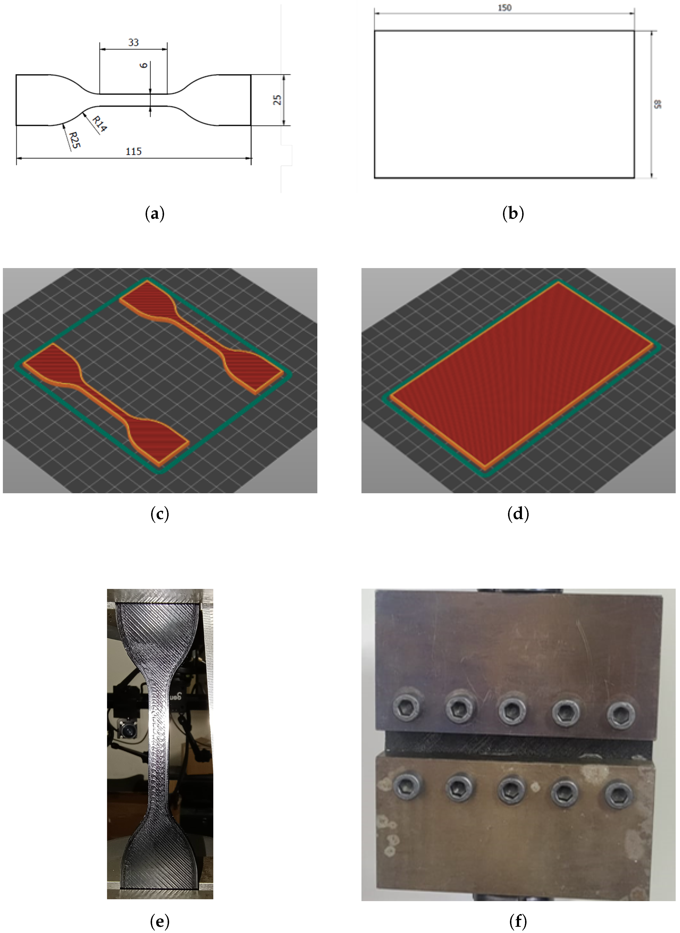
2.1. Samples Manufacturing

Fused Filament Fabrication is an AM technique used to produce 3D objects by extruding a thermoplastic filament through a heated nozzle [11]. The filament, supplied on a spool, is fed into the nozzle, heated, and then deposited in a semi-liquid state. Its quick solidification upon deposition guarantees the formation of thin, connected layers. The desired geometry is built in a layer-by-layer fashion with the coordinated horizontal (X–Y) movement of the printer head and vertical (Z) movement of the build platform. Samples were manufactured employing the ZYYX Pro II printer and two different commercial filaments: unfilled TPU, purchased from Geeetech, and CNT-reinforced TPU, from Essentium. Both filaments have a hardness of 95 Shore A and a diameter of 1.75 mm. The CNT-TPU filament is reinforced externally with CNTs, with a total carbon concentration of approximately 0.01%. The extrusion of the filament in a 0.6 mm nozzle ensures a higher and more random dispersion of CNTs in the samples during the deposition process. The printing parameters, summarized in Table 1, were slightly adapted from those suggested by the manufacturers to achieve the optimal mechanical performance and dimensional compliance for both materials. Figure 1a,b illustrate the two sample geometries investigated: a dumbbell sample for simple tension (ST) testing, whose dimensions were selected according to the ASTM D412 standard [42], and a flat planar tension (PT) sheet. Both samples present a thickness of 3 mm.
The position of the samples on the building base was carefully selected to limit warping and ensure uniformity across the tested conditions. Two ST samples were printed in each batch (Figure 1c), whereas PT samples were manufactured one at a time (Figure 1d). Samples were oriented horizontally on the building base and printed following a 45°-oriented rectilinear path with respect to the tensile orientation, and a 90° orientation change between consecutive layers was selected. Indeed, Xiao et al. [7] reported that the best mechanical properties for FFF-TPU were achieved with a 45°-oriented deposition path, whereas Bruere et al. [19] highlighted that the use of alternating deposition paths improves parts structural integrity. Figure 1e illustrates the ST sample after gripping. To guarantee a pure shear deformation state in planar tension testing, the width of the sample should be much larger than its length with respect to the loading axis [43]. For this reason, the samples were designed with a length–width ratio of at least 1:10 after gripping (as illustrated in Figure 1f) to limit the influence of edge effects at the center of the sample. The cross-sections of both samples were investigated with a DM2500M Optical Microscopy (OM) by Leica Microsystems. Figure 2 reveals typical defects associated with the FFF printing process [5,44], mainly observed at the interfaces between consecutive layers, where incomplete bonding or the formation of gaps between deposited filaments occurred.

2.2. Mechanical Testing

All tests were conducted using an Instron Universal Servo-Hydraulic testing machine with a maximum load capacity of 100 kN, located at the University of Cassino and Southern Lazio. Monotonic ST tests were carried out with a constant cross-head velocity of 500 mm/min, in accordance with the ASTM D412 standard. Cyclic tests were performed using the same cross-head velocity during both loading and unloading to guarantee consistency between the different testing conditions. Samples were unloaded to a force level of approximately 15 N. Six displacement levels were selected for the cyclic loading history, spanning from 10 mm to 60 mm in 10 mm increments, as illustrated in Figure 3. The sample was subjected to either 5 or 20 repetitions for each displacement level. Following the cyclic loading, the material was stretched until failure to investigate its residual strength and flexibility. In PT tests, the cross-head velocity was carefully adjusted to achieve deformation rate levels comparable to those of the ST tests. The samples were clamped using custom-designed grips, as shown in Figure 1f. No slippage was observed between the samples and the grips. After failure, fracture surfaces were investigated by means of Scanning Electron Microscopy (SEM) with a FEI/Philips XL30 Microscope.

3. Results

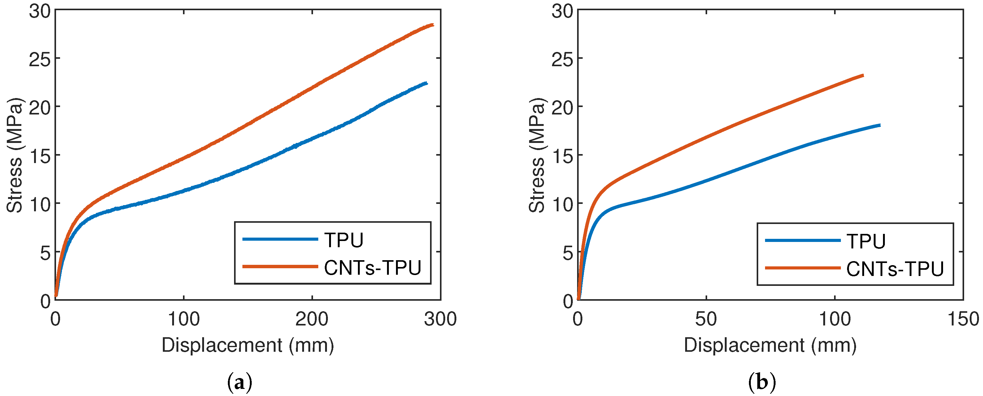
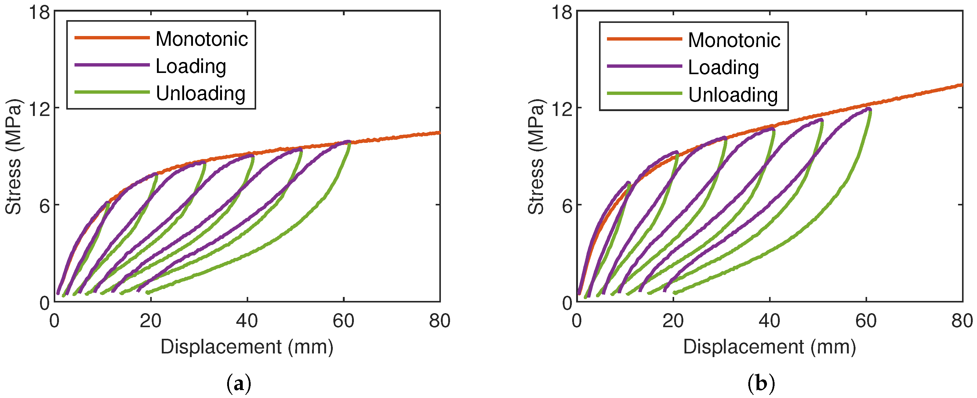
3.1. Monotonic Loadings

This section illustrates the results of monotonic testing conducted on both TPU and CNT-TPU under ST and PT loadings. Tests were performed until the sample failed to investigate the influence of CNTs on both strength and flexibility. Three repetitions were performed for each test; due to the high repeatability of the materials’ response, only a representative curve is presented. Figure 4a illustrates the monotonic engineering stress vs applied displacement curves under ST conditions. Both materials exhibit the non-linear hyperelastic behavior typical of elastomers, and their characteristics are akin to those reported for TPU and MWCNT-TPU in [5,35,45]. Indeed, at very low deformation levels, the materials demonstrate a high initial stiffness, followed by a transition to a plateau region characterized by a relatively constant and lower slope. This behavior is coherent under PT testing as well, as illustrated in Figure 4b. Table 2 summarizes the displacement and stress values measured at the failure point for both materials. The average maximum stress for TPU is 21.8 MPa and 17.7 MPa under ST and PT testing, respectively, whereas it increases to 27.6 MPa and 22.9 MPa for CNT-TPU. The latter material shows an improved mechanical strength of 27–29%, which could be linked to the reinforcement effect due to CNTs [46]. However, no significant variations in the displacement at failure have been recorded, with differences between the two materials lower than 5 % .

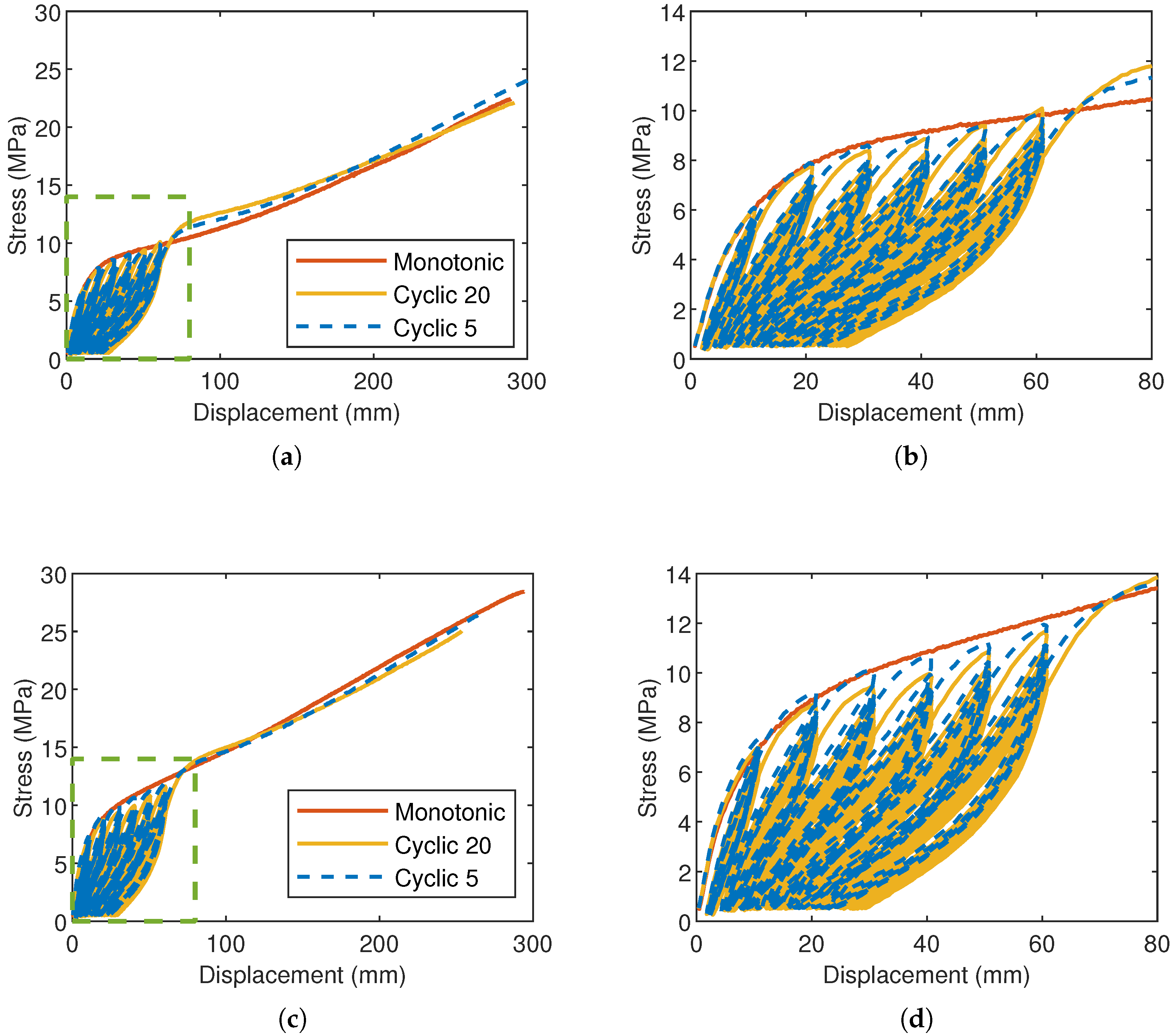
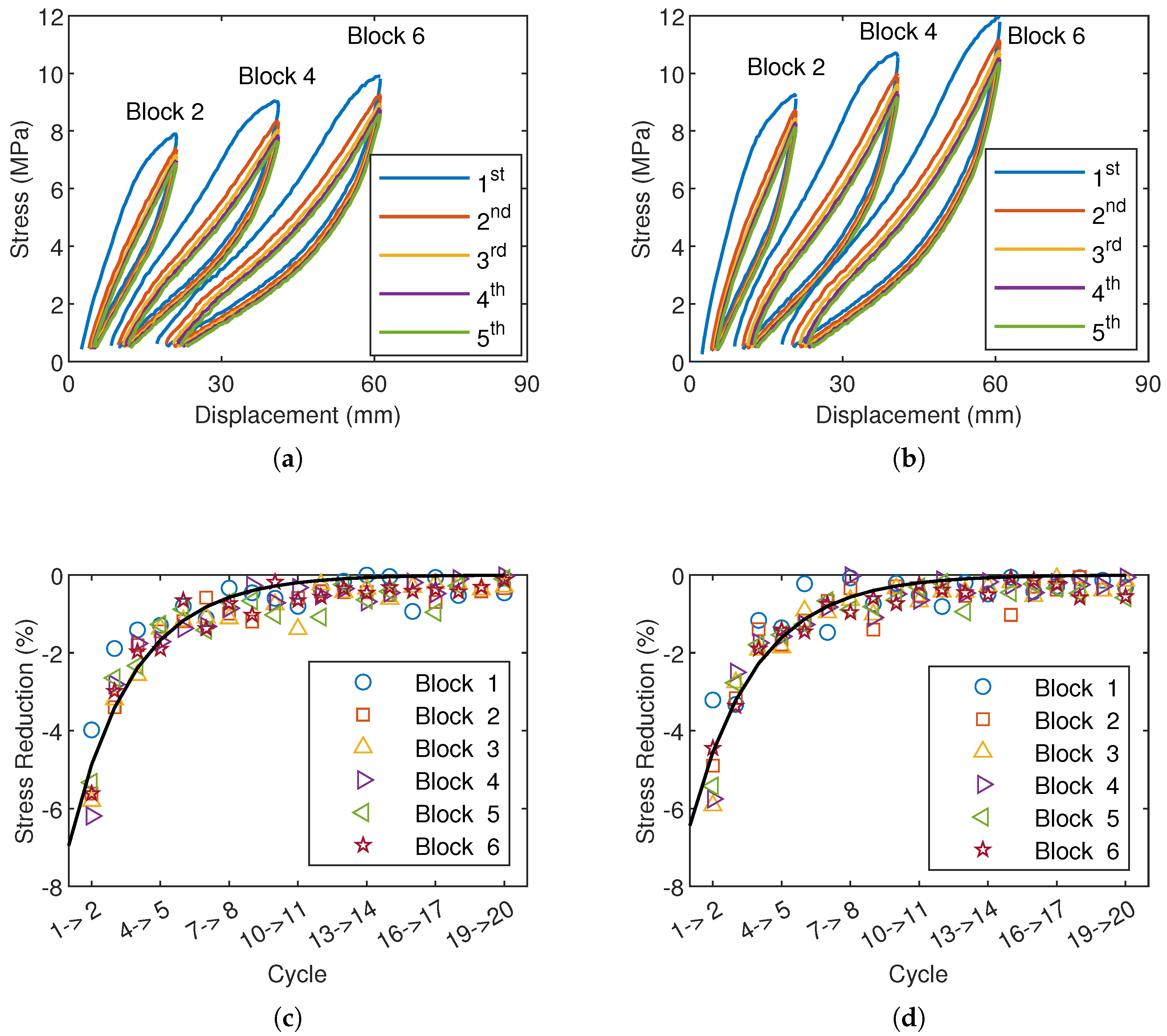
3.2. Cyclic Loadings

The influence of CNTs on material behavior was probed under cyclic loadings by performing ST tests following the loading history illustrated in Figure 3. Figure 5 presents the comparison of the monotonic and cyclic responses, either for 5 and 20 repetitions, for TPU and CNT-TPU. Both materials manifest some of the main characteristics of elastomeric compounds subjected to cyclic loadings, such as the Mullins effect [47], a typical strain-induced stress-softening phenomenon, and the presence of hysteretic behavior and permanent set associated with visco-plastic phenomena [2,48,49]. A more detailed analysis of the materials’ cyclic response is provided in the next section; however, from Figure 5b–d, it is possible to appreciate that:
  • Both materials are characterized by continuous stress softening when subjected to repeated loadings at a given deformation level.
  • Following the first cycles, in which the loss of stiffness is more pronounced, a stabilized cyclic response is gradually reached.
  • Hysteretic loops and permanent set become more noticeable at higher deformation levels [50] and are slightly more pronounced in CNT-TPU, which is consistent with the fact that the presence of fillers enhances viscous effects [51].
Figure 5. Comparison of monotonic and cyclic response under ST loadings. (a) TPU and (b) detail. (c) CNTs-TPU and (d) detail.
Engproc 85 00018 g005
Upon subjecting the material to repeated loadings, even up to 20 repetitions, no substantial alterations in the fracture points were observed. Indeed, as summarized in Table 2, the maximum stress and the displacement at failure under cyclic loadings closely match the monotonic data, and the limited differences found are bounded within the experimental scatter. This observation supports the understanding that the Mullins effect is a discontinuous phenomenon strongly dependent on the applied deformation, and the virgin material response can be restored by increasing the displacement level.

4. Discussion

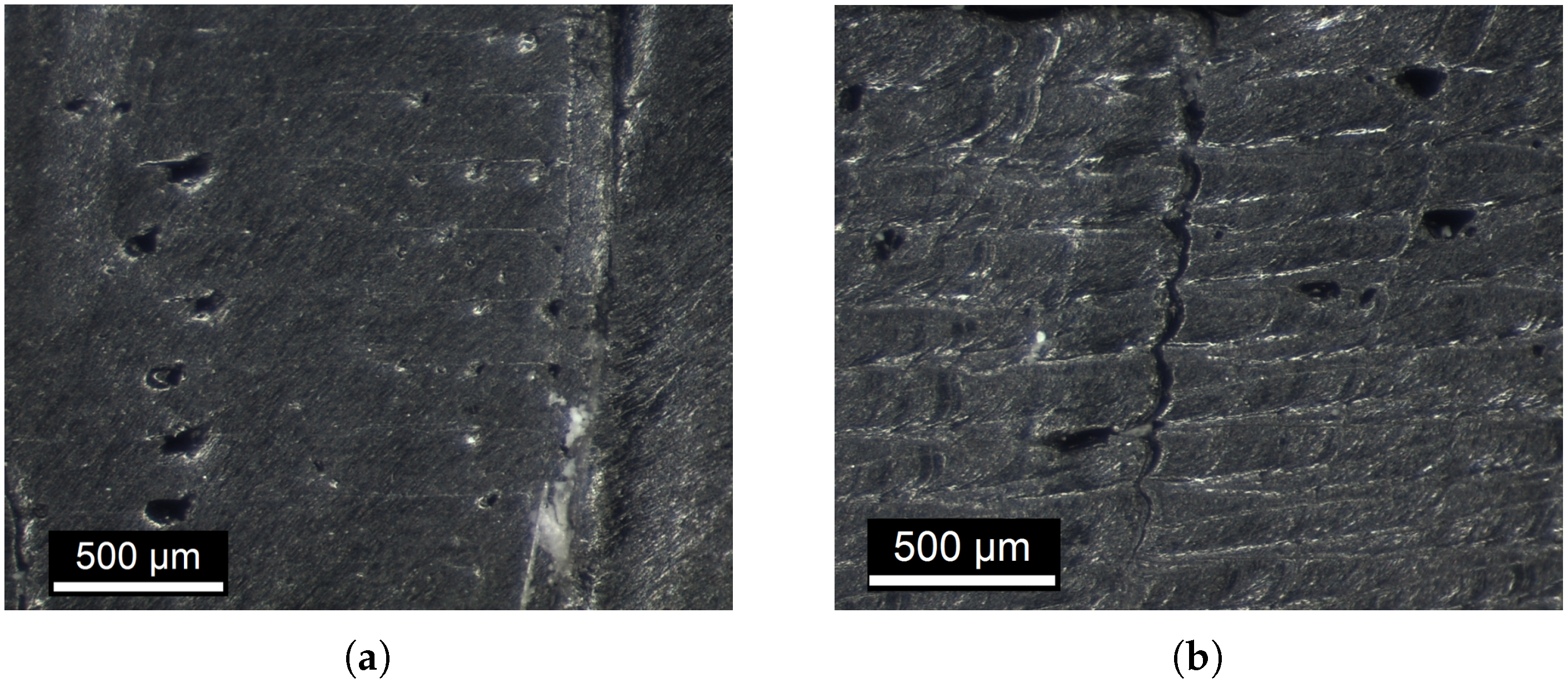
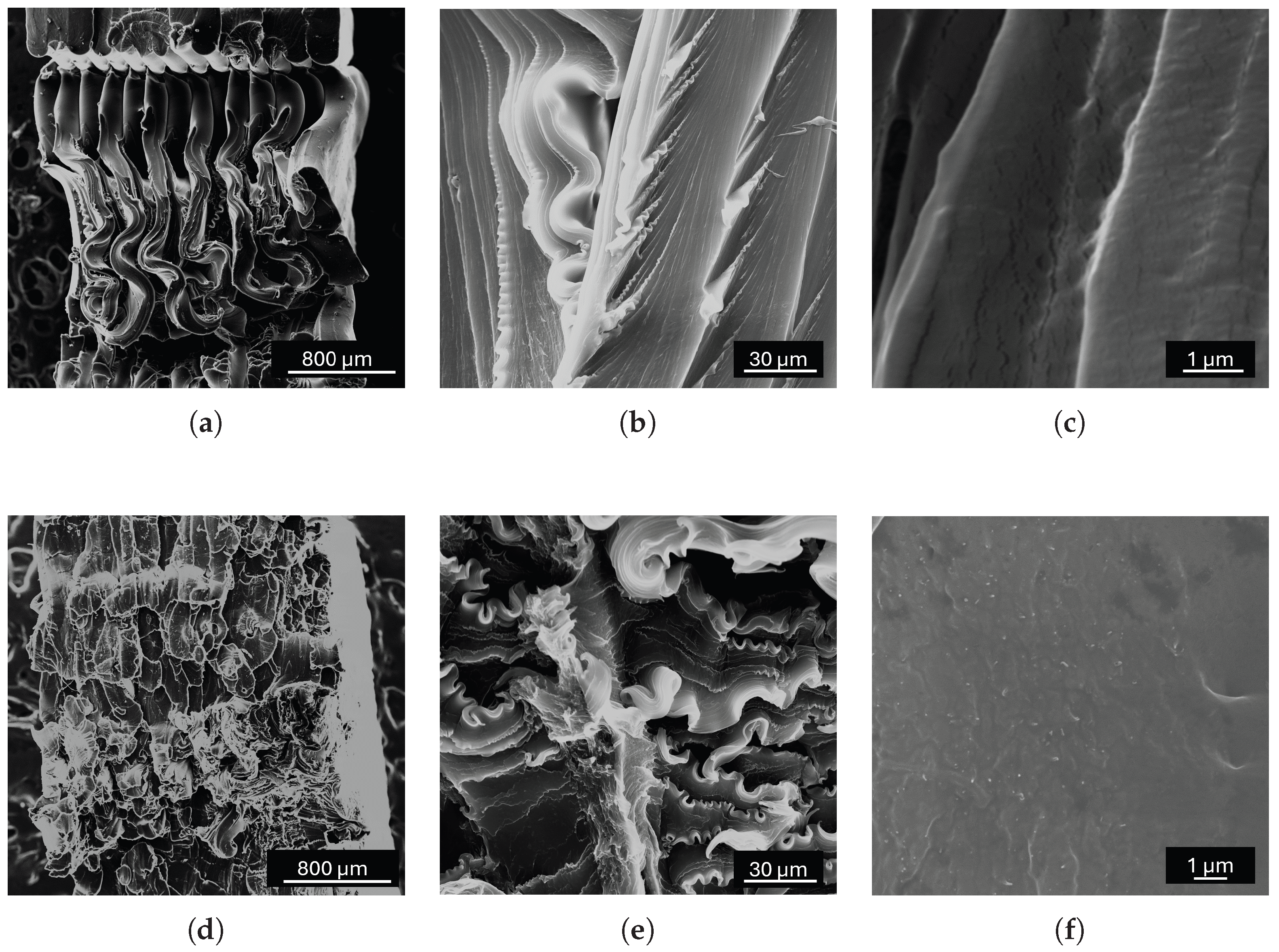
4.1. Monotonic Response and Fracture

From the comparison of the monotonic curves under both simple and planar tension for the two investigated materials, as presented in Figure 4, CNT-TPU demonstrates greater stiffness and strength. More importantly, the inclusion of CNTs does not compromise the material flexibility and elongation at failure. For FFF-TPU, fracture was found to be more influenced by the peculiar microstructure inherent to the deposition technique [40]. The failure stress values for the unfilled material obtained in this study align well with data from the literature for FFF-TPU. For example, Bruere et al. [19] found that, depending on the deposition path, the maximum stress ranged approximately from 10 MPa to 15 MPa. Similarly, Vidakis et al. [12] observed tensile strength values between 15 MPa and 25 MPa, depending on the nozzle temperature and layer thickness. Xiao et al. [7] measured mechanical strength ranging from 31 MPa to 47 MPa in medical-grade FFF-TPU as a function of the selected printing parameters. Kumar et al. [35] attributed the enhanced mechanical strength of filled TPU, even with amounts of MWCNTs as low as 0.1%, to the fine and homogeneous dispersion of CNTs, which provide high load-bearing capacity. In contrast, the observed decline in mechanical properties with increasing MWCNT content was linked to agglomeration phenomena. Similarly, Kim et al. [31] investigated MWCNT-TPU composites produced via the FFF technique and also observed an overall decrease in mechanical performance as the filler content increased, associated with both agglomeration effects and lower layer bonding. The fracture surface analysis of TPU and CNT-TPU under monotonic ST loadings, shown in Figure 6a–d, reveals a characteristic morphology resulting from the FFF deposition process. Distinct fibrous stacks related to the manufacturing technique are clearly visible, consistent with observations by Arifvianto et al. [52]. Figure 6b–e illustrate the presence of ridges and surface irregularities, similar to what was described in [53] for aged TPU, which can be attributed to the extensive deformation experienced by the polymer matrix. This suggests a failure mechanism characterized by significant stretching, rotation, and tearing. Minimal delamination between consecutive layers was found, which was instead reported in [12]. Voids and micro-cracks observed in the TPU matrix, as shown in Figure 6c, can be linked to the high strain levels the material endured before failure. Additionally, Figure 6f illustrates CNTs (white dots) embedded in the rubber matrix. Such a fine and uniform dispersion of CNTs in certain areas of the polymeric matrix likely contributes to the improved strength observed in CNT-TPU, with minimal influence on material elasticity when compared to unfilled TPU [35].

4.2. Analysis of Cyclic Data

4.2.1. Response During the 1st Cycle

Figure 7a,b depict the behavior of TPU and CNT-TPU, respectively, during the first loading–unloading cycle in a series of five repetitions at the selected displacement levels. Considering the 1st cycle at 10 mm, both materials follow a less stiff unloading path if compared to loading. The Mullins effect [47] is often observed in rubber materials subjected to cyclic loads [54,55,56]. In an idealized scenario where only this effect influences mechanical response, the material, when reloaded, would follow the previous unloading path as long as the maximum strain previously applied is not exceeded [57]. Beyond that point, it would deform in accordance with the virgin response. However, rubber-like materials might be characterized by a more intricate inelastic behavior, such as hysteresis effects associated with viscous phenomena [2], resulting in different loading and unloading paths within each cycle, as further investigated in the next section. From Figure 7a,b, it is clear that when both materials are reloaded, they follow a different path from the previous unloading curve. By exceeding the previous applied deformation level, the materials responses gradually rejoin the virgin ones [58,59]. Furthermore, with each loading, a certain degree of deformation (permanent set) is retained, limiting their ability to fully return to the initial undeformed shape. However, part of this deformation can be recovered with time [60]. The Mullins effect has been associated with various microstructural changes, raptures, and evolutions during stretching, as comprehensively reported by Diani et al. [59]. Its physical explanation for TPU can be found in the evolution of their peculiar two-phase microstructure, composed of soft and hard segments [60,61], under cyclic loadings. The first ones are basically polyester or polyether, whereas the latter ones are composed of isocyanates [27,62]. The soft domain is responsible for their extensive elastic behavior, exhibiting a low glass transition temperature [63]. Instead, the hard and rigid segments are below their glass transition temperature at room temperature and, thus, cause higher stiffness and inelastic phenomena such as hysteresis and permanent set [61,64], acting as physical cross-links in the polymeric matrix [2]. The permanent set accumulated at 20, 40, and 60 mm during the 1st unloading over five repetitions was measured to be 4.2, 10.1, and 19.4 mm for TPU, respectively. For CNT-TPU, the residual set was 4.5, 10.6, and 20.4 mm. At the same deformation levels, the area enclosed between loading–unloading curves (force vs displacement) was computed to be 2.8, 5.2, and 6.9 J for unfilled TPU, and 3.4, 6.2, and 8.1 J for CNT-TPU. These results suggest that, even at low concentrations, the presence of nano-fillers in the polymer matrix induces slight changes in the cyclic and viscous behavior of TPU. Diani et al. [59] and Dargazany et al. [49] reported that both the stress-softening effect and the permanent set are amplified by increasing the maximum applied deformation. The filler content also plays a substantial role in magnifying inelastic phenomena [51,65]. For instance, Wang et al. [45] reported a more significant hysteresis and residual strain in AT-filled TPU under cyclic loadings as the filler content increased. They attributed this phenomenon to the physical cross-links formed between the filler and the matrix, which led to increased viscous friction between the polymeric chains.

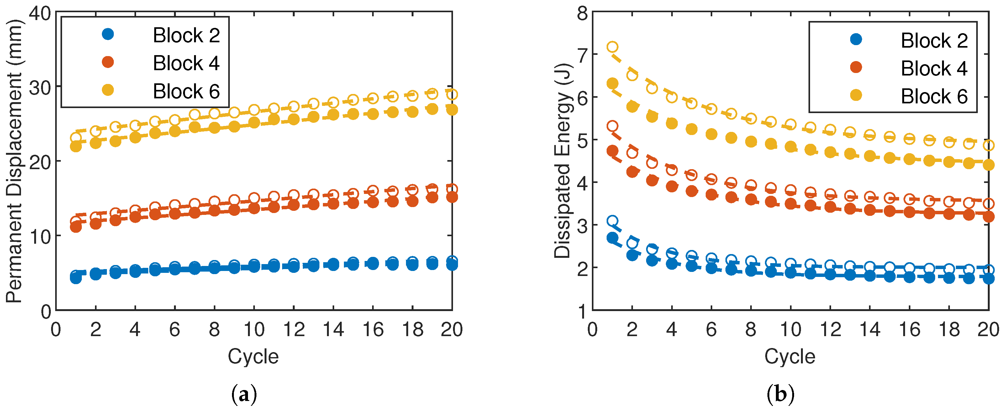
4.2.2. Response Under Repeated Loadings

Both TPU and CNT-TPU display significant stress-softening during the first cycle. However, the stress-displacement curves during the first five cycles, illustrated in Figure 8a,b for TPU and CNT-TPU, highlight the presence of slight, yet still observable, changes in material response in subsequent cycles as well, with narrower loading–unloading loops indicating reduced energy dissipation. The change in shape in the stress–strain loops at different deformation levels can be associated with changes and rearrangement of the polymeric matrix under straining, a phenomenon often observed in these materials. In fact, the behavior exhibited by FFF TPU in this study aligns well with findings reported in the literature for the conventional counterpart. Qi and Boyce [2] observed that the stress–strain curve of the second cycle is more compliant than that of the first, where the most pronounced softening effect occurs. Similarly, Avanzini and Gallina [64] noted a change in the shape of the stabilized stress–strain curve, if compared to the first cycle, with narrower loading–unloading loops. They attributed the softening behavior of TPU under cyclic loading to two key factors: the mechanical reorganization of the hard domains and thermal effects due to material self-heating. Indeed, part of the energy dissipated in the hysteresis is converted into heat [3]. Wang et al. [45] demonstrated that the extent of the hysteretic loop during the first cycle is strongly influenced by the filler content, whereas subsequent cycles show a reduced sensitivity to this factor. The peak stress reduction as a function of the cycle number is depicted in Figure 8c,d. As expected, this reduction is most pronounced during the first cycles, after which it progressively diminishes, with minimal variations observed beyond the 10th cycle. In the transition from the 1st to the 2nd cycle, the extent of stress reduction depends on the applied displacement level. For a displacement level of 10 mm, both materials exhibit the lowest stress reduction, measuring 3.9 % for TPU and 3.2 % for CNT-TPU. As the applied displacement increases, this effect becomes more pronounced, with average values of 5.6 % for TPU and 5.3 % for CNT-TPU. The stress reduction between consecutive cycles was fit with an exponential law, y = A exp ( b x ) , and the best-fit coefficients were calculated as A = 9.93 and b = 0.37 for TPU, and A = 9.11 and b = 0.34 for CNT-TPU. From the negligible differences between these coefficients, it is possible to state that both materials demonstrate similar behavior in terms of stress reduction across successive cycles.
The comparison of accumulated permanent set and dissipated energy measured in the loading–unloading loop (force vs displacement) at different displacement levels is shown in Figure 9. Both materials exhibit comparable behaviors, yet filled TPU demonstrates a higher energy dissipation and permanent set upon unloading. Figure 9a illustrates the evolution of the permanent set as a function of repeated cycles for various displacement levels. For the lowest applied displacement (Block 2, 20 mm), there are no pronounced differences between the two materials, and neither material shows a significant increase in the accumulated permanent deformation for repeated loadings. In contrast, at higher applied deformation levels, the permanent set progressively increases with the number of cycles, following a trend that is well described by a linear relationship. For an applied displacement of 40 mm (Block 4), the slope of the fitted linear expression is 0.19 mm/cycle for TPU and 0.21 mm/cycle for CNT-TPU. These values increase to 0.26 mm/cycle and 0.29 mm/cycle, respectively, at an applied displacement of 60 mm (Block 6). The area enclosed by the loading–unloading curve (force vs displacement) is largest in the first cycle (Figure 9b) and then decreases gradually, following an exponential trend. No substantial changes are observed after the 10th cycle, as also shown in the stress-softening response, indicating a stabilized material behavior. At each deformation level, CNT-TPU exhibits higher dissipated energy compared to unfilled TPU, and the differences between the two materials are more pronounced as the deformation level increases. This confirms that inelastic phenomena are amplified by both increasing the applied deformation and filler content [45,51].

5. Conclusions

The mechanical behavior of unfilled and CNT-reinforced FFF TPU was assessed in this study. Process parameters were optimized for both materials to achieve the optimum mechanical performance and dimensional compliance. The results of monotonic testing, performed under simple and planar tension, highlighted that the integration of CNTs resulted in higher material stiffness and strength without reducing its elasticity. Fracture surfaces revealed the typical morphology of FFF materials; however, failure was accompanied by the severe deformation and stretching of the polymeric matrix, indicating the good quality of the printed parts. Under cyclic loadings, both materials exhibited the typical characteristics of polymeric compounds: strain-induced stress-softening effects (Mullins) and viscous phenomena. Minimal differences in the cyclic softening response were found. At the same time, the accumulated permanent set and the dissipated energy over each cycle were found to be slightly higher in filled TPU. This study was motivated by the fact that the application of AM techniques and the incorporation of innovative elements (such as CNTs) as fillers could be extremely useful for performance improvement in all those fields (for instance, automotive) that strongly rely on rubber-like materials.

Author Contributions

Conceptualization, S.R., G.I. and N.B.; methodology, G.I. and S.R.; software, A.C.; validation, S.R., G.I. and N.B.; formal analysis, S.R.; investigation, S.R., G.I. and A.C.; resources, G.I. and N.B.; data curation, A.C. and A.P.; writing—original draft preparation, S.R.; writing—review and editing, G.I. and N.B.; visualization, G.I.; supervision, N.B.; project administration, G.I. and N.B.; funding acquisition, N.B. All authors have read and agreed to the published version of the manuscript.

Funding

This study was carried out within the MOST–Sustainable Mobility Center and received funding from the European Union Next-GenerationEU (PIANO NAZIONALE DI RIPRESA E RESILIENZA (PNRR)–MISSIONE 4 COMPONENTE 2, INVESTIMENTO 1.4–D.D. 1033 17/06/2022, CN00000023). This manuscript reflects only the authors’ views and opinions, neither the European Union nor the European Commission can be considered responsible for them.

Institutional Review Board Statement

Not applicable.

Informed Consent Statement

Not applicable.

Data Availability Statement

The original contributions presented in the study are included in the article; further inquiries can be directed to the corresponding author.

Conflicts of Interest

The authors declare no conflicts of interest. The funders had no role in the design of the study; in the collection, analyses, or interpretation of data; in the writing of the manuscript; or in the decision to publish the results.

References

  1. Desai, S.M.; Sonawane, R.Y.; More, A.P. Thermoplastic polyurethane for three-dimensional printing applications: A review. Polym. Adv. Technol. 2023, 34, 2061–2082. [Google Scholar] [CrossRef]
  2. Qi, H.J.; Boyce, M.C. Stress-strain behavior of thermoplastic polyurethanes. Mech. Mater. 2005, 37, 817–839. [Google Scholar] [CrossRef]
  3. Wang, S.; Tang, S.; He, C.; Wang, Q. Cyclic Deformation and Fatigue Failure Mechanisms of Thermoplastic Polyurethane in High Cycle Fatigue. Polymers 2023, 15, 899. [Google Scholar] [CrossRef] [PubMed]
  4. Hohimer, C.J.; Petrossian, G.; Ameli, A.; Mo, C.; Pötschke, P. 3D printed conductive thermoplastic polyurethane/carbon nanotube composites for capacitive and piezoresistive sensing in soft pneumatic actuators. Addit. Manuf. 2020, 34, 101281. [Google Scholar] [CrossRef]
  5. Wang, J.; Yang, B.; Lin, X.; Gao, L.; Liu, T.; Lu, Y.; Wang, R. Research of TPU materials for 3D printing aiming at non-pneumatic tires by FDM method. Polymers 2020, 12, 2492. [Google Scholar] [CrossRef]
  6. Dezianian, S.; Azadi, M. Multi-Material Metamaterial Topology Optimization to Minimize the Compliance and the Constraint of Weight: Application of Non-Pneumatic Tire Additive-Manufactured with PLA/TPU Polymers. Polymers 2023, 15, 1927. [Google Scholar] [CrossRef]
  7. Xiao, J.; Gao, Y. The manufacture of 3D printing of medical grade TPU. Prog. Addit. Manuf. 2017, 2, 117–123. [Google Scholar] [CrossRef]
  8. Chennell, P.; Feschet-Chassot, E.; Sautou, V.; Mailhot-Jensen, B. Preparation of ordered mesoporous and macroporous thermoplastic polyurethane surfaces for potential medical applications. J. Biomater. Appl. 2018, 32, 1317–1328. [Google Scholar] [CrossRef]
  9. Zhao, W.; Li, M.; Peng, H.X. Functionalized MWNT-doped thermoplastic polyurethane nanocomposites for aerospace coating applications. Macromol. Mater. Eng. 2010, 295, 838–845. [Google Scholar] [CrossRef]
  10. Ahmed, S.; Nauman, S.; Khan, Z.M. Development of TPU/CNPs flexible composite strain sensors using Additive Manufacturing (AM) for Structural Health Monitoring (SHM) of aerospace components. In Proceedings of 18th International Bhurban Conference on Applied Sciences and Technologies, IBCAST 2021, Islamabad, Pakistan, 12–16 January 2021; pp. 47–54. [Google Scholar] [CrossRef]
  11. Dey, A.; Eagle, I.N.R.; Yodo, N. A review on filament materials for fused filament fabrication. J. Manuf. Mater. Process. 2021, 5, 69. [Google Scholar] [CrossRef]
  12. Vidakis, N.; Petousis, M.; Korlos, A.; Velidakis, E.; Mountakis, N.; Charou, C.; Myftari, A. Strain rate sensitivity of polycarbonate and thermoplastic polyurethane for various 3d printing temperatures and layer heights. Polymers 2021, 13, 2752. [Google Scholar] [CrossRef] [PubMed]
  13. Faisal, M.F.; Akbar, N.I.; Zayed, A.H.H. Development and Analysis of Additively Manufactured Non-Pneumatic Tires for Mars Rover. IOP Conf. Ser. Mater. Sci. Eng. 2024, 1305, 012026. [Google Scholar] [CrossRef]
  14. Herzog, D.; Seyda, V.; Wycisk, E.; Emmelmann, C. Additive manufacturing of metals. Acta Mater. 2016, 117, 371–392. [Google Scholar] [CrossRef]
  15. Lewandowski, J.J.; Seifi, M. Metal Additive Manufacturing: A Review of Mechanical Properties. Annu. Rev. Mater. Res. 2016, 46, 151–186. [Google Scholar] [CrossRef]
  16. Bertocco, A.; Iannitti, G.; Caraviello, A.; Esposito, L. Lattice structures in stainless steel 17-4PH manufactured via selective laser melting (SLM) process: Dimensional accuracy, satellites formation, compressive response and printing parameters optimization. Int. J. Adv. Manuf. Technol. 2022, 120, 4935–4949. [Google Scholar] [CrossRef]
  17. Ricci, S.; Zucca, G.; Iannitti, G.; Ruggiero, A.; Sgambetterra, M.; Rizzi, G.; Bonora, N.; Testa, G. Characterization of Asymmetric and Anisotropic Plastic Flow of L-PBF AlSi10Mg. Exp. Mech. 2023, 63, 1409–1425. [Google Scholar] [CrossRef]
  18. Ricci, S.; Iannitti, G. Mechanical Behavior of Additive Manufacturing (AM) and Wrought Ti6Al4V with a Martensitic Microstructure. Metals 2024, 14, 1028. [Google Scholar] [CrossRef]
  19. Bruère, V.M.; Lion, A.; Holtmannspötter, J.; Johlitz, M. The influence of printing parameters on the mechanical properties of 3D printed TPU-based elastomers. Prog. Addit. Manuf. 2023, 8, 693–701. [Google Scholar] [CrossRef]
  20. Gibson, I.; Rosen, D.; Stucker, B.; Khorasani, M. Additive Manufacturing Technologies; Springer: Cham, Switzerland, 2023. [Google Scholar] [CrossRef]
  21. Deng, S.; Chen, R.; Duan, S.; Jia, Q.; Hao, X.; Zhang, L. Research progress on sustainability of key tire materials. SusMat 2023, 3, 581–608. [Google Scholar] [CrossRef]
  22. Sardinha, M.; Fátima Vaz, M.; Ramos, T.R.; Reis, L. Design, properties, and applications of non-pneumatic tires: A review. Proc. Inst. Mech. Eng. Part L J. Mater. Des. Appl. 2023, 237, 2677–2697. [Google Scholar] [CrossRef]
  23. Suvanjumrat, C.; Rugsaj, R. Study of 3D printing for forming spoke of non-pneumatic tire using finite element method. IOP Conf. Ser. Mater. Sci. Eng. 2021, 1137, 012020. [Google Scholar] [CrossRef]
  24. Domingues, J.; Marques, T.; Mateus, A.; Carreira, P.; Malça, C. An Additive Manufacturing Solution to Produce Big Green Parts from Tires and Recycled Plastics. Procedia Manuf. 2017, 12, 242–248. [Google Scholar] [CrossRef]
  25. Toncheva, A.; Brison, L.; Dubois, P.; Laoutid, F. Recycled tire rubber in additive manufacturing: Selective laser sintering for polymer-ground rubber composites. Appl. Sci. 2021, 11, 8778. [Google Scholar] [CrossRef]
  26. Whelan, D. Thermoplastic Elastomers. In Brydson’s Plastics Materials: Eighth Edition; Butterworth-Heinemann: Oxford, UK, 2017; pp. 653–703. [Google Scholar] [CrossRef]
  27. Deng, Y.; Wang, Z.; Shen, H.; Gong, J.; Xiao, Z. A comprehensive review on non-pneumatic tyre research. Mater. Des. 2023, 227, 111742. [Google Scholar] [CrossRef]
  28. Chen, S.; Yu, H.; Ren, W.; Zhang, Y. Thermal degradation behavior of hydrogenated nitrile-butadiene rubber (HNBR)/clay nanocomposite and HNBR/clay/carbon nanotubes nanocomposites. Thermochim. Acta 2009, 491, 103–108. [Google Scholar] [CrossRef]
  29. Lu, Y.; Liu, J.; Hou, G.; Ma, J.; Wang, W.; Wei, F.; Zhang, L. From nano to giant? Designing carbon nanotubes for rubber reinforcement and their applications for high performance tires. Compos. Sci. Technol. 2016, 137, 94–101. [Google Scholar] [CrossRef]
  30. Danafar, F.; Kalantari, M. A Review of Natural Rubber Nanocomposites Based on Carbon Nanotubes. J. Rubber Res. 2018, 21, 293–310. [Google Scholar] [CrossRef]
  31. Kim, H.; Jeon, J.; Lee, S.; Cho, J.; Lee, I. Printing Characteristics of TPU/MWCNT Conductive Composite Using FFF. Int. J. Precis. Eng. Manuf. 2024, 25, 1303–1309. [Google Scholar] [CrossRef]
  32. Testa, G.; Esposito, L.; Ceccacci, A.; Iannitti, G.; Bonora, N. Innovative design and prototyping of reconfigurable run-flat tire. Eng. Proc. 2024, Under Review. [Google Scholar]
  33. Zhang, R.; Deng, H.; Valenca, R.; Jin, J.; Fu, Q.; Bilotti, E.; Peijs, T. Strain sensing behaviour of elastomeric composite films containing carbon nanotubes under cyclic loading. Compos. Sci. Technol. 2013, 74, 1–5. [Google Scholar] [CrossRef]
  34. Sang, Z.; Ke, K.; Manas-Zloczower, I. Effect of carbon nanotube morphology on properties in thermoplastic elastomer composites for strain sensors. Compos. Part A Appl. Sci. Manuf. 2019, 121, 207–212. [Google Scholar] [CrossRef]
  35. Kumar, S.; Gupta, T.K.; Varadarajan, K.M. Strong, stretchable and ultrasensitive MWCNT/TPU nanocomposites for piezoresistive strain sensing. Compos. Part B Eng. 2019, 177, 107285. [Google Scholar] [CrossRef]
  36. Rostami, A.; Moosavi, M.I. High-performance thermoplastic polyurethane nanocomposites induced by hybrid application of functionalized graphene and carbon nanotubes. J. Appl. Polym. Sci. 2020, 137, 48520. [Google Scholar] [CrossRef]
  37. Sui, G.; Liu, D.; Liu, Y.; Ji, W.; Zhang, Q.; Fu, Q. The dispersion of CNT in TPU matrix with different preparation methods: Solution mixing vs melt mixing. Polymer 2019, 182, 121838. [Google Scholar] [CrossRef]
  38. Tzounis, L.; Petousis, M.; Grammatikos, S.; Vidakis, N. 3D printed thermoelectric polyurethane/multiwalled carbon nanotube nanocomposites: A novel approach towards the fabrication of flexible and stretchable organic thermoelectrics. Materials 2020, 13, 2879. [Google Scholar] [CrossRef]
  39. Zhou, M.; Zhu, W.; Yu, S.; Tian, Y.; Zhou, K. Selective laser sintering of carbon nanotube–coated thermoplastic polyurethane: Mechanical, electrical, and piezoresistive properties. Compos. Part C Open Access 2022, 7, 100212. [Google Scholar] [CrossRef]
  40. Hohimer, C.; Aliheidari, N.; Mo, C.; Ameli, A. Mechanical behavior of 3D printed multiwalled carbon nanotube/thermoplastic polyurethane nanocomposites. In Proceedings of the ASME 2017 Conference on Smart Materials, Adaptive Structures and Intelligent Systems SMASIS2017, Snowbird, UT, USA, 18–20 September 2017. [Google Scholar]
  41. Testa, G.; Bonora, N.; Esposito, L.; Iannitti, G. Design of an electromechanical testing machine for elastomers’ fatigue characterization. Eng. Proc. 2024, Under Review. [Google Scholar]
  42. ASTM D412-16; Standard Test Methods for Vulcanized Rubber and Thermoplastic Elastomers-Tension. ASTM International: West Conshohocken, PA, USA, 2016. [CrossRef]
  43. Giannis, S.; Adams, R.D. Failure of elastomeric sealants under tension and shear: Experiments and analysis. Int. J. Adhes. Adhes. 2019, 91, 77–91. [Google Scholar] [CrossRef]
  44. Rodríguez-Parada, L.; De La Rosa, S.; Mayuet, P.F. Influence of 3D-printed TPU properties for the design of elastic products. Polymers 2021, 13, 2519. [Google Scholar] [CrossRef]
  45. Wang, Y.; Luo, W.; Huang, J.; Peng, C.; Wang, H.; Yuan, C.; Chen, G.; Zeng, B.; Dai, L. Simplification of Hyperelastic Constitutive Model and Finite Element Analysis of Thermoplastic Polyurethane Elastomers. Macromol. Theory Simulations 2020, 29, 2000009. [Google Scholar] [CrossRef]
  46. Khan, U.; May, P.; O’Neill, A.; Vilatela, J.J.; Windle, A.H.; Coleman, J.N. Tuning the mechanical properties of composites from elastomeric to rigid thermoplastic by controlled addition of carbon nanotubes. Small 2011, 7, 1579–1586. [Google Scholar] [CrossRef] [PubMed]
  47. Mullins, L. Softening of rubber. Rubber Chem. Technol. 1969, 42, 339–362. [Google Scholar] [CrossRef]
  48. Palmieri, G.; Sasso, M.; Chiappini, G.; Amodio, D. Mullins effect characterization of elastomers by multi-axial cyclic tests and optical experimental methods. Mech. Mater. 2009, 41, 1059–1067. [Google Scholar] [CrossRef]
  49. Dargazany, R.; Itskov, M. Constitutive modeling of the Mullins effect and cyclic stress softening in filled elastomers. Phys. Rev. E-Stat. Nonlinear Soft Matter Phys. 2013, 88, 012602. [Google Scholar] [CrossRef]
  50. Bartolomé, L.; Aurrekoetxea, J.; Urchegui, M.A.; Tato, W. The influences of deformation state and experimental conditions on inelastic behaviour of an extruded thermoplastic polyurethane elastomer. Mater. Des. 2013, 49, 974–980. [Google Scholar] [CrossRef]
  51. Dorfmann, A.; Ogden, R.W. A constitutive model for the Mullins effect with permanent set in particle-reinforced rubber. Int. J. Solids Struct. 2004, 41, 1855–1878. [Google Scholar] [CrossRef]
  52. Arifvianto, B.; Iman, T.N.; Prayoga, B.T.; Dharmastiti, R.; Salim, U.A.; Mahardika, M.; Suyitno. Tensile properties of the FFF-processed thermoplastic polyurethane (TPU) elastomer. Int. J. Adv. Manuf. Technol. 2021, 117, 1709–1719. [Google Scholar] [CrossRef]
  53. Boubakri, A.; Haddar, N.; Elleuch, K.; Bienvenu, Y. Impact of aging conditions on mechanical properties of thermoplastic polyurethane. Mater. Des. 2010, 31, 4194–4201. [Google Scholar] [CrossRef]
  54. Brieu, M.; Diani, J.; Mignot, C.; Moriceau, C. Response of a carbon-black filled SBR under large strain cyclic uniaxial tension. Int. J. Fatigue 2010, 32, 1921–1927. [Google Scholar] [CrossRef]
  55. Verron, E.; Chagnon, G.; Gornet, L.; Marckmann, G.; Verron, E.; Chagnon, G.; Gornet, L.; Marckmann, G.; Charrier, P.; Verron, E.; et al. Modelling the Mullins effect using damage mechanics: Efficiency and limitations. In Proceedings of the Third European Conference on Constitutive Models for Rubber (ECCMR 2003), London, UK, 15–17 September 2003. [Google Scholar]
  56. Chai, A.B.; Verron, E.; Andriyana, A.; Johan, M.R. Mullins effect in swollen rubber: Experimental investigation and constitutive modelling. Polym. Test. 2013, 32, 748–759. [Google Scholar] [CrossRef]
  57. Ricker, A.; Kröger, N.H.; Wriggers, P. Comparison of discontinuous damage models of Mullins-type. Arch. Appl. Mech. 2021, 91, 4097–4119. [Google Scholar] [CrossRef]
  58. Mars, W.V.; Fatemi, A. Observations of the constitutive response and characterization of filled natural rubber under monotonic and cyclic multiaxial stress states. J. Eng. Mater. Technol. 2004, 126, 19–28. [Google Scholar] [CrossRef]
  59. Diani, J.; Fayolle, B.; Gilormini, P. A review on the Mullins effect. Eur. Polym. J. 2009, 45, 601–612. [Google Scholar] [CrossRef]
  60. Reyes, S.I.; Vassiliou, M.F.; Konstantinidis, D. Experimental characterization and constitutive modeling of thermoplastic polyurethane under complex uniaxial loading. J. Mech. Phys. Solids 2024, 186, 105582. [Google Scholar] [CrossRef]
  61. Cho, H.; Mayer, S.; Pöselt, E.; Susoff, M.; Veld, P.J.; Rutledge, G.C.; Boyce, M.C. Deformation mechanisms of thermoplastic elastomers: Stress-strain behavior and constitutive modeling. Polymer 2017, 128, 87–99. [Google Scholar] [CrossRef]
  62. Frick, A.; Borm, M.; Kaoud, N.; Kolodziej, J.; Neudeck, J. Microstructure and thermomechanical properties relationship of segmented thermoplastic polyurethane (TPU). AIP Conf. Proc. 2014, 1593, 520–525. [Google Scholar] [CrossRef]
  63. Álvarez-García, S.; Martín-Martínez, J.M. Effect of the carbon black content on the thermal, rheological and mechanical properties of thermoplastic polyurethanes. J. Adhes. Sci. Technol. 2015, 29, 1136–1154. [Google Scholar] [CrossRef]
  64. Avanzini, A.; Gallina, D. Effect of cyclic strain on the mechanical behavior of a thermoplastic polyurethane. J. Eng. Mater. Technol. 2011, 133, 021005. [Google Scholar] [CrossRef]
  65. Omnès, B.; Thuillier, S.; Pilvin, P.; Grohens, Y.; Gillet, S. Effective properties of carbon black filled natural rubber: Experiments and modeling. Compos. Part A Appl. Sci. Manuf. 2008, 39, 1141–1149. [Google Scholar] [CrossRef]
Figure 1. Technical drawings of the (a) ST sample and (b) PT sample. Preview of the printing job in the slicing software, (c) ST, and (d) PT samples. Images of the (e) ST and (f) PT samples after gripping.
Engproc 85 00018 g001
Figure 2. Cross-sections of the samples (a) TPU and (b) CNT-TPU. In the micrographs, the printing direction (Z) is vertically oriented.
Engproc 85 00018 g002
Figure 3. Example of loading history for repeated cycles. Solid lines denote the first and last cycles, while dashed lines represent the intermediate cycles. The red star indicates the fracture point.
Engproc 85 00018 g003
Figure 4. Monotonic stress–displacement curves for (a) ST and (b) PT.
Engproc 85 00018 g004
Figure 6. Fracture surfaces under monotonic ST loadings. TPU: (a) overview of the fracture surface; (b,c) higher magnification micrographs. CNT-TPU: (d) overview the fracture surface; (e,f) higher magnification micrographs.
Engproc 85 00018 g006
Figure 7. Stress–displacement response under ST during the 1st loading–unloading cycle at different displacement levels and a comparison with the monotonic behavior for (a) TPU and (b) CNT-TPU.
Engproc 85 00018 g007
Figure 8. Changes in the cyclic stress–displacement response of (a) TPU and (b) CNT-TPU under ST during the first five cycles. Normalized peak stress reduction between consecutive cycles for (c) TPU and (d) CNT-TPU. Fitting with an exponential law y = A exp ( b x ) (black solid lines).
Engproc 85 00018 g008
Figure 9. (a) Evolution of the permanent set over 20 cycles at different displacement levels. Fitting with a linear law (dashed line). (b) Dissipated energy over 20 cycles at different displacement levels. Fitting with an exponential law (dashed line). Data for TPU (filled symbols) and CNT-TPU (open symbols).
Engproc 85 00018 g009
Table 1. Printing parameters for TPU and CNT-reinforced TPU.
TPUCNTs-Reinforced TPU
Nozzle Temperature (°C)205225
Chamber Temperature (°C)4055
Nozzle diameter (mm)0.60.6
Average Printing Speed (mm/s)2020
Extrusion multiplier (-)0.980.93
Layer height (mm)0.20.2
Infill density (%)100100
Infill geometryRectilinear 45°-orientedRectilinear 45°-oriented
Infill combinationEach layerEach layer
Table 2. Summary of test results. Average values and standard deviation.
TPUCNTs-TPU
ST-MonotonicFracture Stress21.8 ± 1.2 MPa27.6 ± 1.4 MPa
Final Displacement280.5 ± 9.5 mm284.0 ± 16.0 mm
ST-5 cyclesFracture Stress22.6 ± 3.2 MPa26.8 ± 0.4 MPa
Final Displacement291.3 ± 36.4 mm272.5 ± 11.3 mm
ST-20 cyclesFracture Stress22.9 ± 1.1 MPa25.7 ± 0.9 MPa
Final Displacement298.9 ± 9.5 mm286.6 ± 21.3 mm
PT-MonotonicFracture Stress17.7 ± 1.4 MPa22.9 ± 0.5 MPa
Final Displacement117.2 ± 7.7 mm110.3 ± 1.2 mm
Disclaimer/Publisher’s Note: The statements, opinions and data contained in all publications are solely those of the individual author(s) and contributor(s) and not of MDPI and/or the editor(s). MDPI and/or the editor(s) disclaim responsibility for any injury to people or property resulting from any ideas, methods, instructions or products referred to in the content.

