Abstract
Unmanaged waste can cause environmental pollution, as well as hygiene and health problems. Sitimulyo Piyungan Bantul at the coordinates of −7.86409, 110.42888 was established in 1994 and is the final waste repository area in Yogyakarta, and it is now completely closed; consequently, causing joblessness in the surrounding community. There are activities that can be undertaken to recycle waste such as managing rubbish. Waste can be divided into four categories scrapping, composting, and producing maggot food. However, unmanaged and useful waste, namely, inorganic and hazardous waste, remains a big problem. This research work aims to solve the problem by re-engineering and making an initial simulation using computational fluid dynamics of an incinerator to complete unmanaged inorganic and hazardous rubbish. The incinerator was produced to process non-organic solid and medical waste, which should be combusted at temperatures higher than 800 °C to reduce combustible rubbish that can no longer be recycled, and toxic chemicals, to kill bacteria and viruses. The main incinerator frame is made of an iron elbow. Construction of the incinerator is divided into the chamber, recirculation zone, and chimneys. The wall of the incinerator machine is made of refractory stone and insulators. To measure and control the temperature, thermocouples and a thermocontrol are placed at the inner wall of the incinerator machine. The function of the incinerator machine was tested, and it ran normally. Initial operation of an incinerator for solid hazardous waste such as infusion bottles, pets, glass bottles, pampers, and expired medicines was undertaken. The performance showed that the achieved temperature was 705 °C during the process of the operation, and all of the hazardous waste became ash and the recycled material became a paving block that is economically worthwhile. Hence, the incinerator can be operated as a household industrial tool for a solid medical waste processing apparatus. An initial computational study of the incinerator was also carried out briefly using the student version of commercial software.
1. Introduction
Hazardous waste is all waste generated from hospital activities in solid, liquid, paste, or gas form that can contain infectious pathogenic microorganisms, toxic chemicals, and some are radioactive. Hospital waste tends to be infectious and toxic chemicals that can affect human health and worsen environmental sustainability if not managed properly. Solid hospital waste, better known as hospital waste, is something that is not used, not liked, or something that must be disposed of that generally comes from activities carried out by humans, and is generally solid [1,2]. Solid hospital waste is all hospital waste in solid form due to hospital activities, and consists of solid medical and non-medical waste (Decree of the Minister of Health of the Republic of Indonesia No. 1204/MENKES/SK/X/2004) [3]. The incineration process is one alternative method of waste processing that is used effectively. This system has advantages including being able to produce heat energy and requiring a short degradation time compared to composting, landfill, and open dumping systems. The incineration process can reduce the volume of waste by up to 90% while composting, landfill, and open dumping can only reduce the volume by 40%. Incineration according to [4,5,6,7] is a solid waste processing process by burning at a temperature of more than 800 °C to reduce combustible waste that can no longer be recycled, and kill bacteria, viruses, and toxic chemicals. This process is carried out in a tool called an incinerator. One of the advantages that continue to be developed in the latest technology for incinerators is that waste can be destroyed quickly and in a controlled manner, and it does not require a large area. Research conducted by [8] made this cylindrical incinerator using refractory bricks for the walls of the combustion chamber. For combustion, this incinerator uses three gas-fueled burners. Research by [9] conducted an evaluation of the processing of B3 solid waste from combustion at Dr. Soetomo Hospital, Surabaya. The incinerator used for combustion is the Rotary Kiln type. In one day, the incinerator at Dr. Soetomo Hospital can burn medical waste four times. The average combustion temperature is 900 °C. The current constraint on the use of incinerator technology is that it still requires a lot of combustion energy from fuel oil or gas, so that the operational costs of the incinerator are high and the price of the incinerator is relatively very expensive. Ref. [10] conducted a study by analyzing the solid waste processing of the Kudus Regency Regional Hospital. This suboptimal combustion is likely caused by the short residence time of medical solid waste in the incinerator and the temperature required to destroy the medical solid waste is not too high. To overcome this, incinerator machine technology was developed that is expected to overcome these problems for energy-efficient medical solid waste processing. Therefore, an incinerator was made without a burner as the main burner, which will save combustion energy so that operational costs are low, making the cost of the incinerator relatively cheap. Making this incinerator is also simpler compared to making a burner system incinerator.
2. Literature Study
A study that tested the incinerator’s operating capability to reduce clinical waste was conducted at the Haji General Hospital in Surabaya [11]. This study showed that the incinerator’s capability to reduce waste reached 85% for 3–4 h. The incinerator’s capability based on process time and mass weight follows first-order reaction kinetics and optimum k (reaction rate) = 1.0132 with 5 kg mass and minimum k = 0.6839 at 30 kg mass [12]. A study evaluated solid medical waste processing at the Gatot Soebroto Army Central Hospital. Similar solid waste processing of the Kudus Regency Regional Hospital in the introduction, the incinerator used at the Gatot Soebroto Army Hospital has a burning capacity of 5 m3 with a Controlled Air Incinerator type equipped with pollution control in the form of a wet chamber and Hazard Particle Preventer. A study analyzed the solid waste processing of Kudus District Hospital. This suboptimal combustion is likely caused by the short residence time of the medical solid waste in the incinerator, and the temperature required to destroy the medical solid waste is not that high as state on brick wall experiment previously. A study analyzed B3 waste processing at PT Toyota Motor Manufacturing Indonesia. The B3 waste management system used an incinerator, and the DRE value produced was 80.59%, which still does not meet the quality standards of the Kep-03/Bapedal/09/1995 regulation [13], which is 99.99%. The non-optimal temperature causes incomplete combustion, so that the DRE efficiency is less than 99%. This is due to the less-than-optimal use of the incinerator [14]. A study designed a prototype of a radioactive waste incinerator furnace. The manufacture of this furnace uses bricks consisting of a mixture of refractory cement, stone sand, and building cement. The ratio is 1:1:1, which is then mixed with water and molded. For combustion, this furnace uses three burner units that use oil fuel [7]. A study evaluated the function of the incinerator in destroying B3 waste at the TNI Hospital in Surabaya. After conducting direct research for 14 consecutive days, it was found that the average B3 waste generation was 89.98 kg/day with an average waste density of 166.67 kg/m3. The removal rate from waste combustion with an incinerator at the TNI Hospital was 82.63% [15]. A study analyzed the use of incinerators in waste processing in the city of Merauke. Final waste disposal using incinerator technology was found to be useful in the city of Merauke to overcome the constraints of the conventional methods currently used [16]. A study designed a municipal waste power generator (PLTSa) incinerator type as an alternative electricity solution for the city of Medan. Penetration of PLTS in the medium-voltage distribution system, also known as Distributed Generation based on Renewable Energy Sources, can improve voltage drop and loss, as well as improve the voltage stability index, in addition to helping add new electrical power to the 20 kV primary distribution network. From the various creations, it can be concluded that the incinerators that were made are still not optimal and require a lot of energy for combustion, so the operational costs of the incinerator are very high. The research being conducted now is to make a solid medical waste incinerator without a burner as the main burner. The technique for making this incinerator is simpler compared to the burner system incinerator, so that effective performance can be obtained, along with energy efficiency and low operational costs, and its manufacture is cheap.
3. Methodology
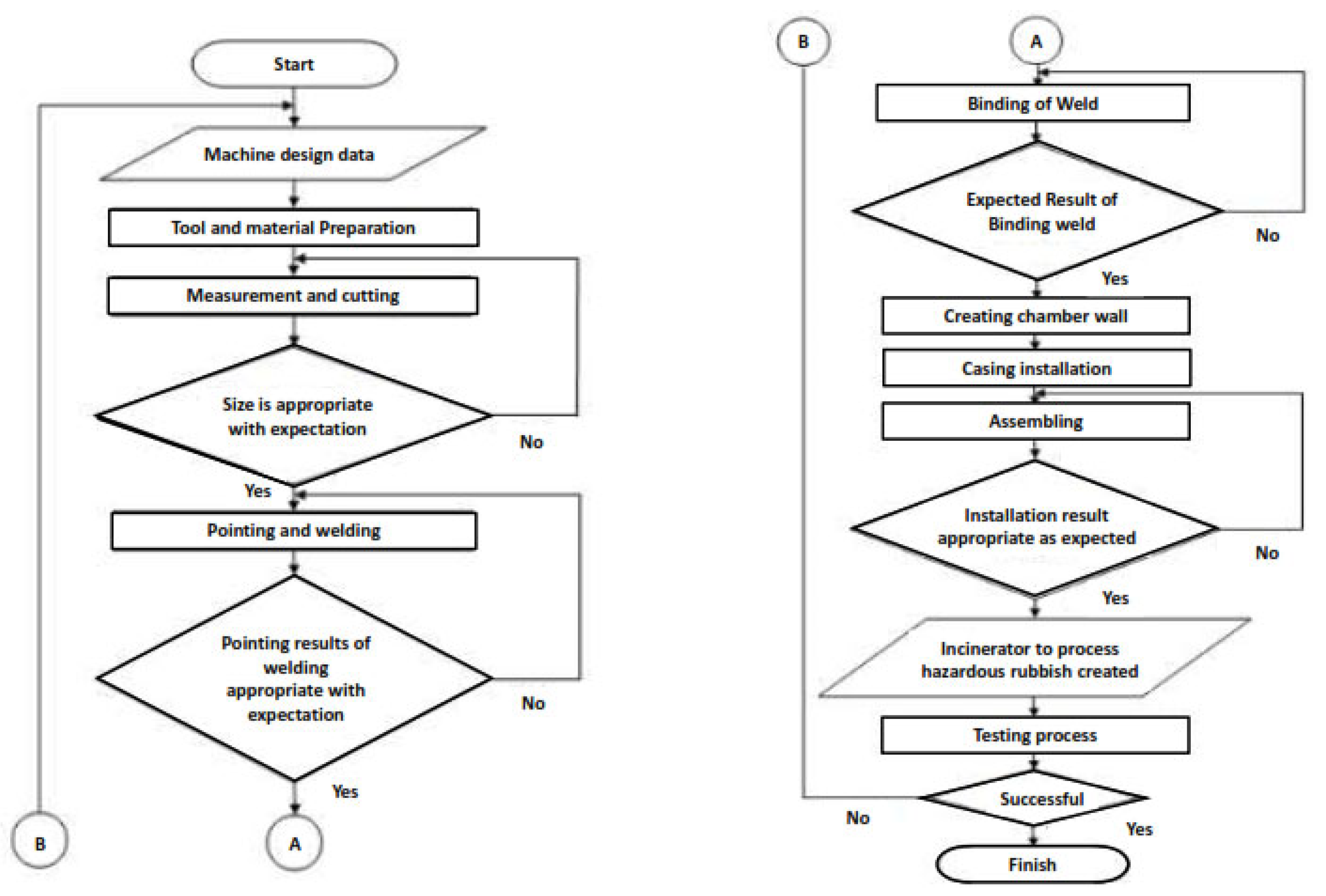
The method of making an incinerator is explained in the flow diagram shown in Figure 1 below.
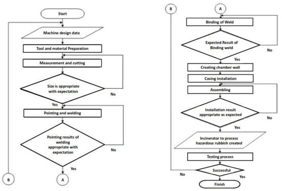
Figure 1.
Flow chart diagram of research.
3.1. Tools and Materials
The tools used to make this medical solid waste incinerator machine include a grinder, electric welding, electric drill, roller ruler, hammer, and compressor. The materials used to make this medical solid waste incinerator machine include 50 mm × 50 mm × 5 mm angle iron, 3 mm steel plate, ø 175 mm pipe, refractory stone, Fire Retardant Cement, soil and sand, glass wool, paint, thermocouple, thermocontrol, anemometer, and materials in the form of solid medical waste and rubbish.
3.2. Experiment Procedure
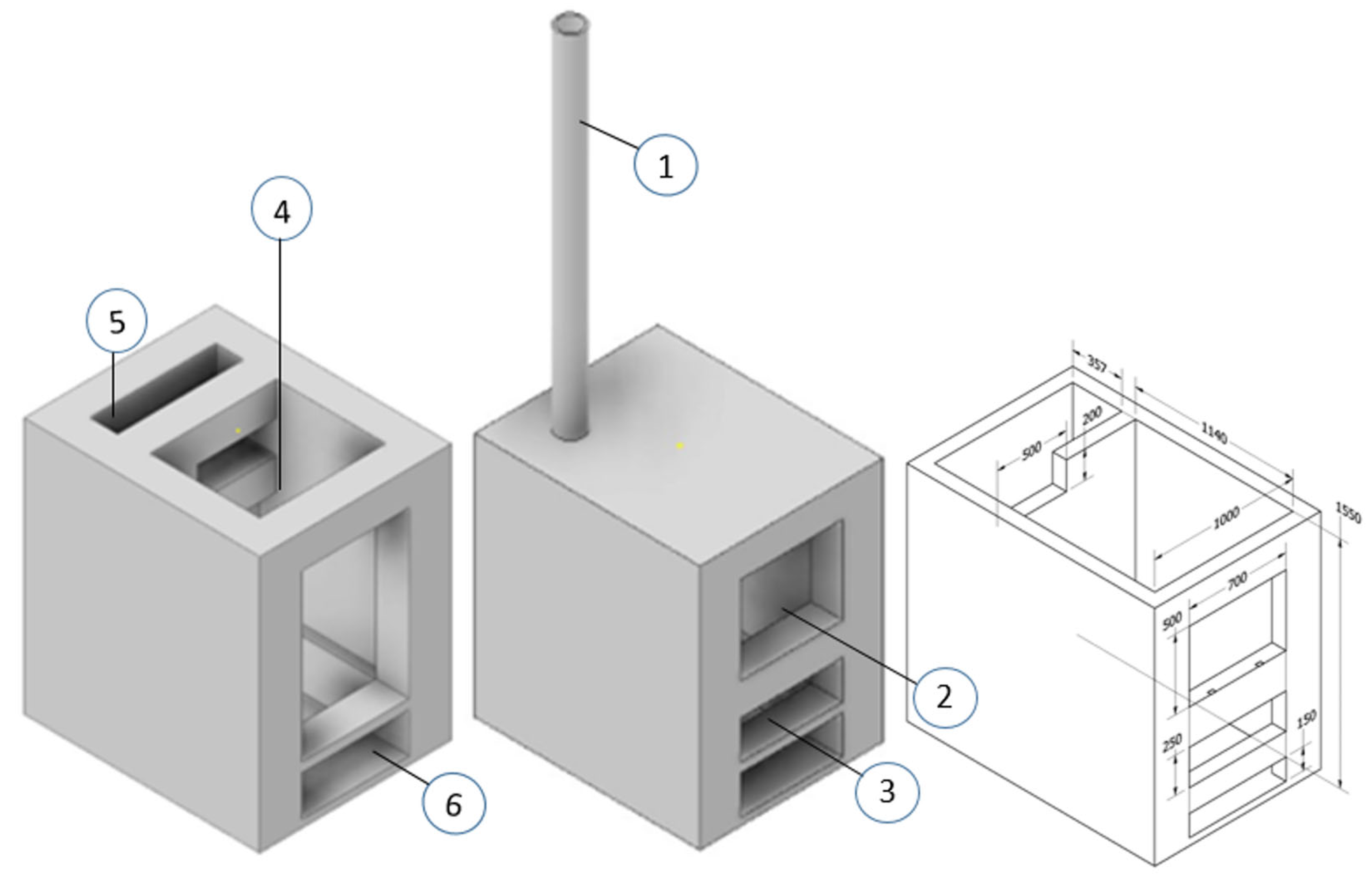
The trial of this incinerator was carried out by burning medical solid waste, namely, infusion bottles, syringes, glass bottles, baby diapers, and expired medicines, with existing operational standards. The burning duration is approximately 25 min or until it produces perfect ash. During the burning process, observations and recordings of the temperature were carried out using thermocouples and temperature control using thermocontrol. Operational trials were conducted on an incinerator that had been designed, as shown in Figure 2 below.
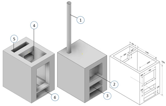
Figure 2.
Incinerator design.
From the process of making incinerators, medical solid waste incinerators are obtained with the following specifications:
- Dimension: 1815 mm × 1200 mm × 1550 mm.
- Main frame: Elbow still (50 mm × 50 mm × 5 mm.
- Main frame burner: 1400 mm × 1200 × 1600 mm.
- Flue circulation room: 357 mm × 1200 mm × 1600 mm.
- Ash room: 1400 mm × 1200 × 150 mm.
- Chamber wall: Refractory stone.
- Casing of incinerator: Iron plate 3 mm thick.
- Chimney: 300 mm height 25 mm.
- System: Without burner.
- Thermocouple: Type K (0~+1000 °C).
4. Result and Discussion
4.1. Result of Construction Process
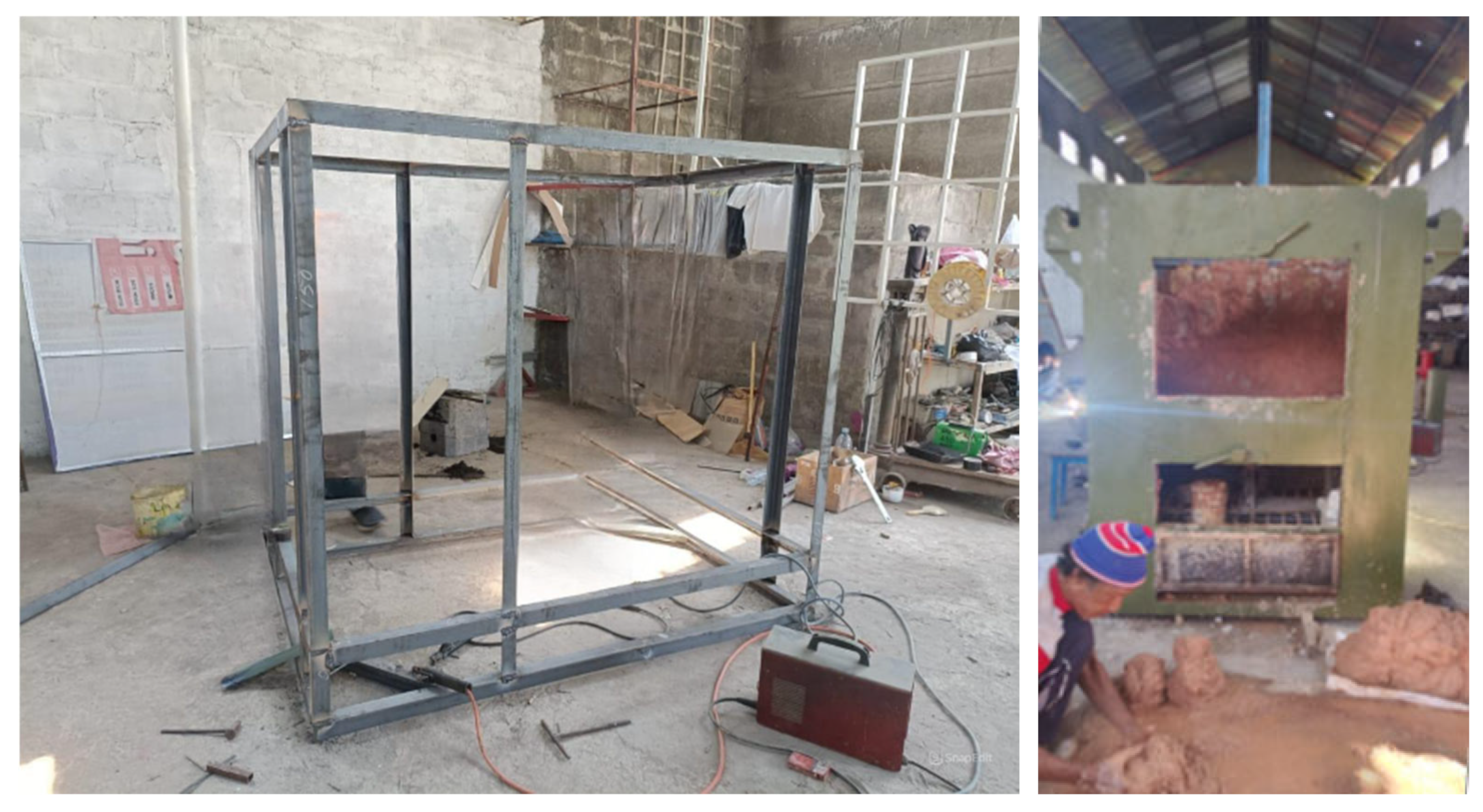
The initial process of making an incinerator is carried out with several appropriate considerations. The area of the waste combustion chamber and the smoke combustion chamber must be compared correctly when making the chamber so that it produces maximum engine work. The results of the initial construction process are shown in Figure 3.

Figure 3.
Construction of Incinerator and installation of refractory stone wall.
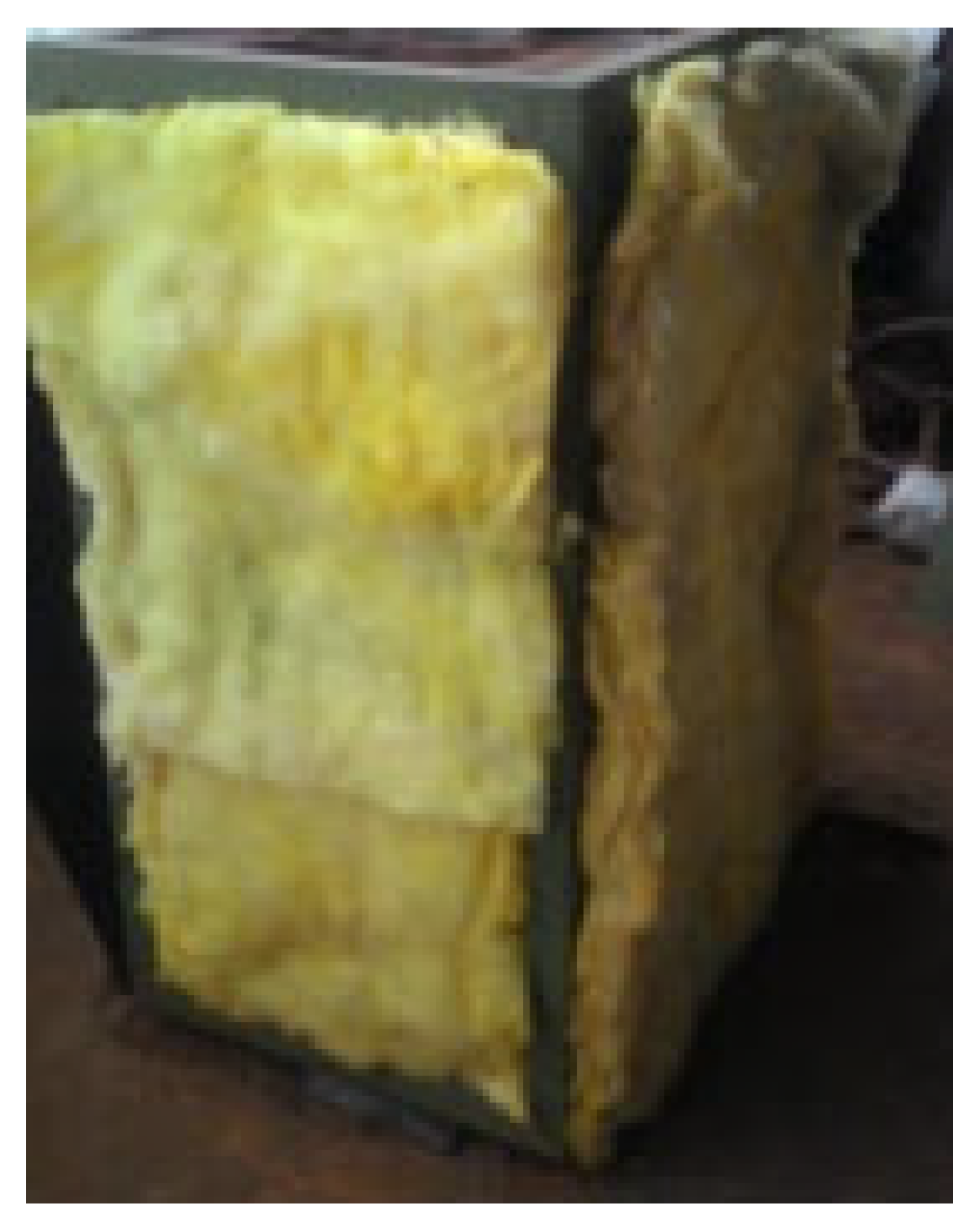
The insulator in an incinerator has a vital role. This insulator uses glass wool as shown on Figure 4. The provisions of an insulator serve as a retainer for the hot room temperature so that it does not conduct directly outside the room through the incinerator casing; if there is a conduction, the casing made of iron plate will bend due to expansion due to heat from the waste combustion chamber.

Figure 4.
Insulator assembly.
The making of the casing on all sides was performed previously and then installed on all sides of the part. The casing of this incinerator uses a 2.8 mm thick iron plate material. The casing functions to protect the insulator and chamber walls from the outside air and as a chamber retainer so that it is not easily damaged. In making this incinerator door, the inner door is given an insulator in the form of casting using castable, which has the function of retaining temperature like the glass wool found on the chamber walls. The chimney is the most important part of the incinerator to drain air out of the chamber. This incinerator is made using a pipe with a diameter of 160 mm, a thickness of 4 mm, and a height of 2290 mm. Putty is applied on the end side of the incinerator and the welding connection part to smooth the connection results. Paint is applied to the casing, door, and chimney of the incinerator. This painting aims to protect the material from corrosion and improve its appearance. Maintenance of the tool components can be undertaken routinely by the user or operator every time the tool is used. Inspection can be undertaken before and after the tool is operated, so it can be identified if there is damage. Checking the chamber wall is conducted to check the physical condition of the bricks after a long period of operation. Frequent maintenance involves cleaning dirt from the remains of burning medical solid waste after operating the incinerator machine. From the results of the temperature test as Figure 5, this tool can reach a temperature of 998 °C and can be operated to process solid medical waste burned into ash except for waste made of plastic, needles, and glass.
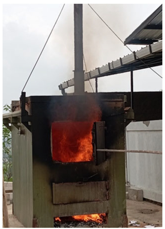
Figure 5.
The produced combustion inorganics and hazardous rubbish at the incinerator.
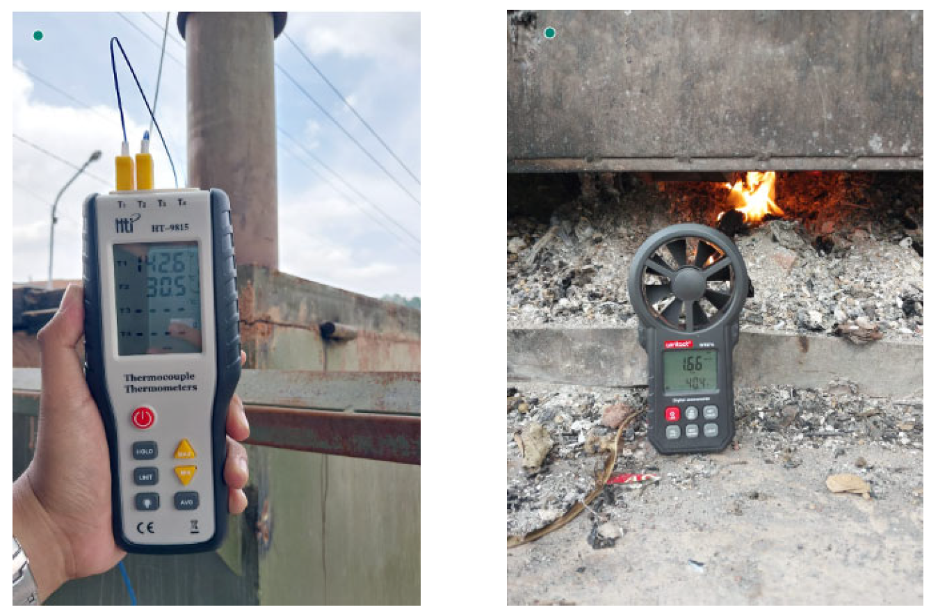
Temperature measurement in the combustion chamber and recirculation area as well as at the chimney was undertaken using a thermocouple. Meanwhile, an anemometer was used to measure the ambient air velocity, and the air velocity entering the combustion chamber of the equipment used, as shown in Figure 6.

Figure 6.
Achieved temperature and incoming wind speed.
4.2. Experimental Data and Discussion
The results of the measurements of the incinerator performance that were made from the beginning obtained various types of information, especially measuring the temperature at various measurement points and air speed and the percentage of waste combustion residue showed at Table 1.

Table 1.
Incinerator temperature and air speed measurement data.
Production Capability: The expected combustion rate efficiency temperature is around 500 °C–1000 °C. The expected waste-burning capacity is 750 kg per day. Meanwhile, over ten days of operation, the incinerator is capable of processing 7000 kg of waste with 250 kg of ash (residue).
Residue and its use: From the results of laboratory tests as Table 2, paving with residue that meets the National Standard Industry (SNI) specifications with a mixture of 30% and 50% residue can be used as a substitute for sand.
Table 2.
Job Mix Design for Residue bricks or paving block.
The following is noted from Table 3, Table 4 and Table 5: For sample 0%, the formwork size used is 15 × 15 cm. And for samples, 10%, 30%, and 50%, the formwork size used is 5 × 5 cm.
Table 3.
Results of water absorption testing wet sample weight.
Table 4.
Results of water absorption testing dry sample weight.
Table 5.
Results of percentage absorption capacity.
Compression test results: It should be noted that compression test results shown on Table 6 for the 0% sample, a formwork size of 15 × 15 cm was used. And for the 10%, 30%, and 50% samples, a formwork size of 5 × 5 cm was used.
Table 6.
Results of compressive strength of concrete bricks.
4.3. Initial of Computational Study
In this computational research, for modeling using commercial software Solidwork 2020, the Solidwork model was saved in the igs extension so that it can be imported into other media or software, and a similar simulation was carried out [17,18,19]. In this simulation, the student version of the Ansys CFX 2021 R2 software was selected, while from the Ansys software, we imported the igs fluid flow (CFX) extension file as part of the computational fluid dynamics (CFD). The process stages through Ansys were to import the geometry and then to do the meshing. The meshing model is a model discretization process so that the solver can calculate the main variables in CFD. The meshing results are then set to the boundary conditions to determine the boundaries of the inlet, outlet, and fluid walls that will pass through the computational domain according to the characteristics and processes desired in the simulation. In this initial simulation, we set the air fluid that will flow into the computational domain to ensure the air flow process and the possibility of modifying the path if there is still less than ideal air flow in the computational domain. The model and meshing results are shown in Figure 7 below.
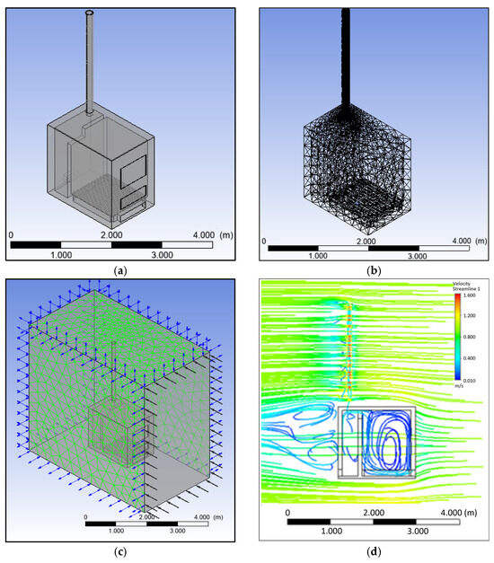
Figure 7.
Incinerator model (a), Meshing process (b), setting boundary condition (c), and result of velocity streamline inside the incinerator (d).
The simulation results are still preliminary, and the flowing fluid is only air. The results involving the transfer of arrow energy will be studied in a separate discussion. The simulation results also show a fairly prospective picture with recirculation flow inside the combustion chamber. A vortex flow was revealed behind the incinerator. Further investigation showed that results provide a direction for recommendations for further studies in the area of heat and mass transfer challenges.
5. Summary
Based on the results achieved from the entire process including the manufacture and testing of the incinerator system without a burner, the following conclusions can be drawn:
- The incinerator manufacturing process begins with making the frame and then continues with making the chamber space by arranging refractory stones. The insulator is installed on the chamber wall with glass wool and then covered with a casing made of a 2.8 mm thick iron plate. The previously made chimney and incinerator door are subsequently installed. The finishing is conducted by filling and painting to prevent corrosion. The last step is to install the thermocouple temperature measuring components and thermo control.
- This incinerator is capable of processing solid medical waste into ash except for needles, plastic, and glass with a temperature reaching 998 °C with a capacity of 5 kg of waste and 8 kg of fuel infusion bottles, syringes, glass bottles, baby diapers, and expired medicines.
- The results of the incinerator recycle residue-produced paving blocks fulfill the specifications of the SNI, and as the initial simulation changed, further study that possibly involves mass and heat transfer is recommended.
Author Contributions
Conceptualization, S.; methodology, S. and A.Y.; software, S. and M.I.O.; validation, S., A.Y. and M.I.O.; formal analysis, A.Y. and S.; investigation, M.I.O.; resources, A.Y.; data curation, S. and M.I.O.; writing—original draft preparation, M.I.O. and S.; writing—review and editing, M.I.O. and A.Y.; visualization, S. and M.I.O.; supervision, A.Y. and S.; project administration, M.I.O.; funding acquisition, S. All authors have read and agreed to the published version of the manuscript.
Funding
This research was funded by Directorate Research technology and Service of Community (DRTPM) and the APC was funded by DRTPM Contract number: 108/E5/PG.02.00.PL/2024 with derived contract number of 007/LL6/PB/AL.04/2024, 196.120/A.3-III/LRI/VI/2024.
Institutional Review Board Statement
The study was conducted in relation to the special obligation duties as Lector and Professor with the approval Dean of Engineering Faculty UMS number: 8-ST/A.3-III/FT/II/2025.
Informed Consent Statement
Not applicable.
Data Availability Statement
Data supporting reported results can be found, on the link of https://drive.google.com/drive/folders/129dDXKK4JNnhGQIqOdCR2eVoFbMFeknb?usp=sharing (accessed on 10 February 2025).
Acknowledgments
This research was supported by LRI and LPMPP Universitas Muhammadiyah Surakarta. My thanks must go to the Directorate of Research and Community Service the Minister of Higher Education Indonesia, through the contract from DRTPM.
Conflicts of Interest
The authors confirm that there are no conflicts of interest to declare for this publication.
References
- Anshory, L. Chemistry Lesson Guide; Ganesa Exact Bandung: Bandung, Indonesia, 1988. [Google Scholar]
- Azwar, A. Introduction to Environmental Health Science; Yayasan Mutiara: Jakarta, Indonesia, 1990. [Google Scholar]
- Decree of the Minister of Health of the Republic of Indonesia No. 1204/MENKES/SK/X/2004. 2024. Available online: https://peraturan.bpk.go.id/Details/111721/permenkes-no-7-tahun-2019 (accessed on 10 February 2025).
- Kavanagh, A. Incineration: A Burning Issue or a Load of Rubbish?’ Examining Public Attitudes to Municipal Solid Waste Incineration. Ph.D. Thesis, Environmental Resource Management Department of Geography, National University of Ireland, Maynooth, Ireland, 2006. [Google Scholar]
- Yan, F.; Zhu, F. Preliminary Study of PM2.5 Formation During Municipal Solid Waste Incineration. Procedia Environ. Sci. 2016, 31, 475–481. [Google Scholar] [CrossRef]
- de B. Parsons, H. Disposal of Municipal Refuse, and Rubbish Incineration. Trans. Am. Soc. Civ. Eng. 2024, 57, 2. [Google Scholar] [CrossRef]
- Saragih, J.L.; Herumurti, W. Evaluation of the Incinerator Function in Destroying B3 Waste at the Dr. Ramelan TNI Hospital, Surabaya. J. Tek. Pomits 2013, 2, 138–143. [Google Scholar]
- Ratman, C.R.; Syafrudin. Implementation of B3 Waste Processing at PT. Toyota Motor Manufacturing Indonesia. J. Presipitasi 2007, 7, 62–70. [Google Scholar]
- Girsang, V.E.; Herumurti, W. Evaluation of B3 Solid Waste Management from Incineration at Dr Soetomo Hospital, Surabaya. J. Tek. Pomits 2013, 2, 46–50. [Google Scholar]
- Nugroho, A.; Handayani, D.S. Solid Waste Management at Kudus District Regional Hospital. J. Presipitasi 2008, 5, 99–103. [Google Scholar]
- Hidayah, E.N. Operational Capability Test of Incinerator to Reduce Clinical Waste at Haji General Hospital Surabaya. J. Rekayasa Perenc. 2007, 4, 9–18. [Google Scholar]
- Pramita, N. Evaluation of Waste Management at Gatot Soebroto Army Central Hospital. J. Presipitasi 2007, 2, 51–55. [Google Scholar]
- Decision Of The Head Of The Environmental Impact Control Agency of the Republic of Indonesia, Kep-03/Bapedal/09/1995. 1995. Available online: https://sib3pop.menlhk.go.id/uploads/Regulasi/BAPEDAL031995.pdf (accessed on 10 February 2025).
- Margono; Rahardjo, H.P. Design and Construction of Radioactive Waste Incinerator Prototype. Nucl. Devices J. 2011, 5, 1–8. [Google Scholar]
- Lolo, D.P. Analysis of Incinerator Use in Waste Processing in Merauke City. Sci. J. 2014, 3, 200211. [Google Scholar]
- Safrizal. Distributed Generator of Municipal Waste Power Plant (PLTSa) Incinerator Type Alternative Electricity Solution for Medan City. J. Tek. 2014, 121–128. [Google Scholar]
- Sarjito, S.; Riyadi, T.W.B. A Parametric Study of Wind Catcher Model in a Typical System of Evaporative Cooling Tower Using CFD. Appl. Mech. Mater. 2014, 660, 659–663. [Google Scholar] [CrossRef]
- Sarjito. An Investigation of the Scope for Improvement of the Performance of Multi-Stage Downdraught Evaporative Coolers Using CFD. Appl. Mech. Mater. 2013, 315, 835–840. [Google Scholar] [CrossRef]
- Sarjito; Aklis, N.; Hartanto, T. An optimization of flap and slat angle airfoil NACA 2410 using CFD. AIP Conf. Proc. 2017, 1831, 020038. [Google Scholar]


Disclaimer/Publisher’s Note: The statements, opinions and data contained in all publications are solely those of the individual author(s) and contributor(s) and not of MDPI and/or the editor(s). MDPI and/or the editor(s) disclaim responsibility for any injury to people or property resulting from any ideas, methods, instructions or products referred to in the content. |
© 2025 by the authors. Licensee MDPI, Basel, Switzerland. This article is an open access article distributed under the terms and conditions of the Creative Commons Attribution (CC BY) license (https://creativecommons.org/licenses/by/4.0/).