
A Preliminary Study on Computer Aided Process Planning for Generating Additive Manufacturing Products via 3D/4D/5D Printing †

Abstract
1. Introduction
2. Methodology
2.1. Designing 3D CAD Models for Additive Manufacturing Products
2.2. Generating 3D/4D/5D Printing Process Planning by a Creation of Macro
- (i)
- If the number of materials is equal to 1 and the number of datums is equal to or greater than 3; the type of printing process is 5D printing.
- (ii)
- If the number of materials is equal to or greater than 2 and the number of datums is equal to or more than 1; the type of printing process is 4D printing.
- (iii)
- Otherwise, the type of printing process is 3D printing.
| Algorithm 1 Required user interaction method for opening the part file |
| Creating variables for SolidWorks application Creating variables for SolidWorks document Creating variables for SolidWorks drawing Declare t1, t2 where t = time Program main function Sub main() Setting variable of SolidWorks Message Box “Please open SolidWorks part file.” t1 = Now t2 = Now + Time Value(“0:00:30”) Do Until t1 ≥ t2 Do Events t1 = Now() Loop Response = Message Box(“File are open?”, Yes or No) If Response = Yes, Then Message Box “Please open drawing for the part.” t1 = Now t2 = Now + Time Value(“0:00:30”) Do Until t1 ≥ t2 Do Events t1 = Now() Loop Else Continue End If Response = Message Box(“Drawing are open?”, Yes or No) If Response = Yes, Then Message Box “Proceed to next part.” Else Continue End If End Sub |
| Algorithm 2 Fully automated method |
| Creating variables for SolidWorks application Creating variables for SolidWorks document Creating variables for SolidWorks drawing Program main function Sub main() Setting variable of SolidWorks Open part file Open drawing file End Sub |
| Algorithm 3 Process for converting 3D CAD model file to STL file |
| Creating variables for Object Creating variables for SolidWorks application Creating variable for SolidWorks document Creating variables for Part Creating variables for Boolean Creating variables for Long |
| Sub main() Setting SolidWorks variable Open 3D CAD model file Save As End Sub |
3. Results and Discussion
4. Conclusions
Author Contributions
Funding
Institutional Review Board Statement
Informed Consent Statement
Data Availability Statement
Acknowledgments
Conflicts of Interest
References
- Kataraki, P.S.; Abu Mansor, M.S. A novel classification of freeform volumetric features and generative CAPP approach for milling machine selection. Int. J. Adv. Manuf. Technol. 2018, 98, 985–1009. [Google Scholar] [CrossRef]
- Zubair, A.F.; Abu Mansor, M.S. Auto-recognition and part model complexity quantification of regular-freeform revolved surfaces through delta volume generations. Eng. Comput. 2020, 36, 511–526. [Google Scholar] [CrossRef]
- Kataraki, P.S.; Abu Mansor, M.S. Automatic designation of feature faces to recognize interacting and compound volumetric features for prismatic parts. Eng. Comput. 2020, 36, 1499–1515. [Google Scholar] [CrossRef]
- Jiang, R.; Kleer, R.; Piller, F.T. Predicting the future of additive manufacturing: A Delphi study on economic and societal implications of 3D printing for 2030. Technol. Forecast. Soc. Chang. 2017, 117, 84–97. [Google Scholar] [CrossRef]
- Yao, Y.; Cheng, L.; Li, Z. A comparative review of multi-axis 3D printing. J. Manuf. Process. 2024, 120, 1002–1022. [Google Scholar] [CrossRef]
- Tang, P.; Zhao, X.; Shi, H.; Hu, B.; Ding, J.; Yang, B.; Xu, W. A review of multi-axis additive manufacturing: Potential, opportunity and challenge. Addit. Manuf. 2024, 83, 104075. [Google Scholar] [CrossRef]
- Korpela, M.; Riikonen, N.; Piili, H.; Salminen, A.; Nyrhilä, O. Additive Manufacturing—Past, Present, and the Future. In Technical, Economic and Societal Effects of Manufacturing 4.0; 2020; pp. 17–41. Available online: https://link.springer.com/book/10.1007/978-3-030-46103-4 (accessed on 21 May 2024).
- Khorram Niaki, M.; Nonino, F.; Palombi, G.; Torabi, S.A. Economic sustainability of additive manufacturing: Contextual factors driving its performance in rapid prototyping. J. Manuf. Technol. Manag. 2019, 30, 353–365. [Google Scholar] [CrossRef]
- Oettmeier, K.; Hofmann, E. Additive manufacturing technology adoption: An empirical analysis of general and supply chain-related determinants. J. Bus. Econ. 2017, 87, 97–124. [Google Scholar] [CrossRef]
- Kim, Y.; Yuk, H.; Zhao, R.; Chester, S.A.; Zhao, X. Printing ferromagnetic domains for untethered fast-transforming soft materials. Nature 2018, 558, 274–279. [Google Scholar] [CrossRef] [PubMed]
- Muthe, L.P.; Pickering, K.; Gauss, C. A Review of 3D/4D Printing of Poly-Lactic Acid Composites with Bio-Derived Reinforcements. Compos. Part C Open Access 2022, 8, 100271. [Google Scholar] [CrossRef]
- Nandi, C.; Caspi, A.; Grossman, D.; Tatlock, Z. Programming language tools and techniques for 3D printing. In Proceedings of the 2nd Summit on Advances in Programming Languages (SNAPL 2017) Leibniz International Proceedings in Informatics (LIPIcs), Asilomar, CA, USA, 7–10 May 2017; Volume 71. [Google Scholar]
- Golovianko, M.; Terziyan, V.; Branytskyi, V.; Malyk, D. Industry 4.0 vs. Industry 5.0: Co-existence, Transition, or a Hybrid. Procedia Comput. Sci. 2023, 217, 102–113. [Google Scholar] [CrossRef]
- Haleem, A.; Javaid, M. Future applications of five-dimensional printing in dentistry. Curr. Med. Res. Pract. 2019, 9, 85–86. [Google Scholar] [CrossRef]


| Type | 3D Printing | 4D Printing | 5D Printing |
|---|---|---|---|
| Design Characteristics | Product has to maintain as a static or fixed shape. The product should be able to be printed by a printer, i.e., up to 3 degrees of freedom. | Product can transform itself into another structure due to the effect of external factors like temperature, heat or light. The product applies smart material such as shape memory polymer. | Product contains complex freeform surface that hard to be printed by the 3D printer. The 5D printer needs to be used since it has 5 degrees of freedom. |
| Type of Printing Process | 3D Printing | 4D Printing | 5D Printing |
|---|---|---|---|
| Number of datums | 2 | 2 | 5 |
| Number of materials (Shape memory material/Smart material = 1, PLA = 2 or Others = 3) | 2 | 1 | 2 |
| Method | Result |
|---|---|
| Required user interaction | 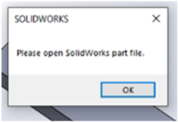 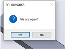 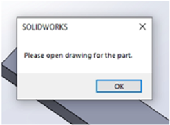 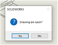 |
| Fully automated | 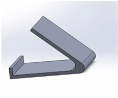 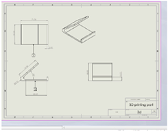 |
| Type of Printing | Result and Explanation |
|---|---|
| 5D printing | 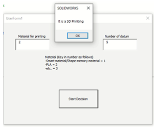 The data that are filled in for 5D part are as follows: Material = 2 and Datum = 5 The decision made by the macro shows that the part should employ 5D printing process. This proves that the part is indeed a 5D printing part. |
| 4D printing | 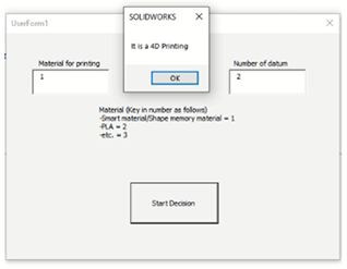 The data that are filled in for 4D part are as follows: Material = 1 and Datum = 2 The decision made by the macro shows that the part should employ 4D printing process. This proves that the part is indeed a 4D printing part. |
| 3D printing | 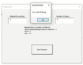 The data that are filled in for 3D part are as follows: Material = 2 and Datum = 2 The decision made by the macro shows that the part should employ 3D printing process. This proves that the part is indeed a 3D printing part. |
| Printing Process | Slicing Process | G-Code Generated |
|---|---|---|
| 3D printing | 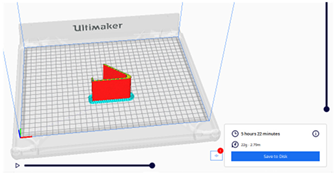 | Able to generate G-code |
| 4D printing | 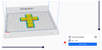 | Able to generate G-code but it needs further investigation since it is generated based on 3D printing process |
| 5D printing | 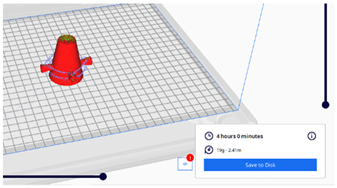 | Able to generate G-code but it needs further investigation since it is generated based on 3D printing process |
Disclaimer/Publisher’s Note: The statements, opinions and data contained in all publications are solely those of the individual author(s) and contributor(s) and not of MDPI and/or the editor(s). MDPI and/or the editor(s) disclaim responsibility for any injury to people or property resulting from any ideas, methods, instructions or products referred to in the content. |
© 2025 by the authors. Licensee MDPI, Basel, Switzerland. This article is an open access article distributed under the terms and conditions of the Creative Commons Attribution (CC BY) license (https://creativecommons.org/licenses/by/4.0/).
Share and Cite
Ilias, I.N.; Abu Mansor, M.S. A Preliminary Study on Computer Aided Process Planning for Generating Additive Manufacturing Products via 3D/4D/5D Printing. Eng. Proc. 2025, 84, 44. https://doi.org/10.3390/engproc2025084044
Ilias IN, Abu Mansor MS. A Preliminary Study on Computer Aided Process Planning for Generating Additive Manufacturing Products via 3D/4D/5D Printing. Engineering Proceedings. 2025; 84(1):44. https://doi.org/10.3390/engproc2025084044
Chicago/Turabian StyleIlias, Izzah Nadhilah, and Mohd Salman Abu Mansor. 2025. "A Preliminary Study on Computer Aided Process Planning for Generating Additive Manufacturing Products via 3D/4D/5D Printing" Engineering Proceedings 84, no. 1: 44. https://doi.org/10.3390/engproc2025084044
APA StyleIlias, I. N., & Abu Mansor, M. S. (2025). A Preliminary Study on Computer Aided Process Planning for Generating Additive Manufacturing Products via 3D/4D/5D Printing. Engineering Proceedings, 84(1), 44. https://doi.org/10.3390/engproc2025084044