Abstract
This paper presents an alternative method of producing 3D calligraphy products that have been created using integrated modern technologies, specifically reverse engineering and CNC machining. Traditionally, calligraphy is performed by hand on any suitable medium, such as on a wall or even on wood, which has drawbacks, i.e., it is time consuming and requires an original drawing or blueprint. To address these drawbacks, this new method utilizes integrated reverse engineering and CNC machining techniques to produce 3D calligraphy products without the need for an original drawing or blueprint, significantly reducing time consumption.
1. Introduction
Initially, Islamic or Arabic calligraphy began at Nil’s River in 3200 B.C. It came from Ancient Egypt’s Hieroglyph system, which then evolved into Hieratic. In China, calligraphy is seldom considered an art. The word “Calligraphy” is not used in China, but it is described as being similar to Chinese handwriting. Chinese thinkers believe that calligraphy can describe one’s personality or manners, either good or bad, through the art of handwriting [1,2]. Calligraphy is an art related to writing that can be divided into two categories, i.e., classic calligraphy and modern calligraphy. Classic calligraphy usually involves using a brush to draw the letter on a piece of paper. Typically, classic calligraphy is readable. It was used regularly in previous eras in China, such as the Dynasty Era. On the other hand, modern calligraphy is designed from a fine-art perspective, where the letters created may or may not be readable. Currently, this form of calligraphy is starting to evolve from drawn letters to three-dimensional calligraphy that requires very skillful hand-work techniques to craft. In Islamic countries, this form of calligraphy can be seen in mosques, where it is found most often on walls as decoration and for communication.
Essentially, a design is used by a designer to produce products, objects, and structures with the aid of existing tools or software that have been utilized globally. For instance, the traditional tools that have been used to draw are pens, T-squares, drafting boards, perspective machines, rulers, French curves, templates, compasses, and drafting machines [3,4]. Today, innovation has become a significant driving force for modern technology for global economic growth. Essentially, innovation is defined as a new way, method, or idea. It also can be described as something that is more effective and original. In addition, innovation can be explained as something that makes an improvement to the existing product or produces a new product which does not yet exist on the market and that can benefit the community [5].
For calligraphy, the same technique is used to produce either classic calligraphy or modern calligraphy by hand. Calligraphy education in the past involved three categories, which include the writing method, for beautiful writing, self-purification, and calligraphy tools [6]. Modern calligraphy has become more akin to typographic design, in that it can be readable or non-readable. Typographic messages can be visual, auditory, or oral. Good typography design graphics can lead to creative and understandable communication between people [7]. New technologies that have been used by researchers include robotic arms and UAV systems that create calligraphic characters [8,9,10]. Reverse engineering, also known as backward engineering, is a technique that can be used to produce a product without having any specific dimensions or a copy of the original product [11,12]. It is a method that represents an important part of prototype creation in which a 3D scanner is utilized as a machine to scan the object and transfer the scanned output of the object to CAD/CAM software [13,14]. There are several types of digitizing devices that can be used, such as contact, laser, optical, and destructive devices. Essentially, the method of reverse engineering used to acquire 1D (point cloud data) or 2D (range images) is performed using digitizing devices such as CMM and laser scanners, or by using photography devices such as ICT, CDD cameras, and MRI [15,16,17].
Reverse engineering also provides many alternatives to producing molds [18]. Moreover, it is cheaper than forward engineering [19,20]. CNC machines can have better control of tool positioning, shorter process planning phases, reduced machining times, and efficient tool utilization, and can cut very complex shapes [21,22]. Notably, a micro lathe machine was produced, measuring only 32 mm, where its length was reduced from 200 mm, successfully reducing the brass wire diameter from 300 micrometers down to 10 micrometers using diamond tools [23,24]. The performance inconsistency in the assembly of machined parts happens due to machining dimension errors. For example, errors such as work piece location and deflection, tool wear and deflection, and clamping can affect the quality of the part. Other errors in CNC machine tools, such as geometrical deviations in machine tool structure, force and stress, cutting force-induced errors, and thermal variations, can affect the accuracy and repeatability of manufactured parts [25,26].
In this study, an alternative innovative method of design for producing 3D calligraphy products aims to address drawbacks due to writing calligraphy by hand in the traditional way, which leads to greater time consumption and requires an original drawing or blueprint. Integrated techniques are used to produce 3D calligraphy products by utilizing reverse engineering and CNC machining, since they can provide automation and precision to modify or replicate existing products. The advantages of the integrated techniques of reverse engineering and CNC machining can benefit manufacturers by increasing productivity, improving new products, and optimizing production costs. Hence, modern technologies such as reverse engineering and CNC machining are used as integrated techniques that can be employed in producing 3D calligraphy, so that it can be sustained innovatively and will not disappear until future generations restore it. Therefore, this study has provided an impactful solution to reduce the time involved in producing 3D calligraphy products without requiring an original drawing or blueprint.
2. Methodology
This study consists of two 3D calligraphy products that need to be produced. The first product is intended to produce innovative designs for “BISMILLAH” calligraphy, and the second product is intended to produce innovative designs for “REVERSE ENGINEERING LAB” typography. Both products used for 3D calligraphy are to be produced using integrated reverse engineering and CNC machining techniques.
The first product is taken from existing BISMILLAH calligraphy, then the next process involves capturing the image of BISMILLAH, going into the editing process, and finally beginning the CNC machining process. For the second product, the REVERSE ENGINEERING LAB typography uses scanning, an editing process, and finally CNC machining. In addition, industrial clay is used for the second product, where the typographic words need to be crafted using crafting tools and the industrial clay. Figure 1 shows the flow chart for this study, from the start to the end of the process for the first product, BISMILLAH calligraphy, and the second product, REVERSE ENGINEERING LAB typography.

Figure 1.
Process flow chart.
2.1. BISMILLAH Calligraphy Product
An image of BISMILLAH calligraphy was captured using a camera and was imported into SolidWorks 2023 software. The software was utilized to create a product based on the image. Once finished, the created profile was extruded with a thickness of 5 mm. A rectangle below the word BISMILLAH was created to act as a base. Cutting was performed on the edge of the product. In the design, the final process produced a cylindrical feature on the right-hand side of the rectangle. An aluminum plate with a dimension of 200 mm × 100 mm × 13 mm was cut and placed in the machine. The side of the aluminum plate needed to be milled to obtain a flat surface because the machine needed to set its location of origin. After going through this process, the aluminum plate was placed into the CNC wire cutting machine. An NC code was automatically generated from the drawing. The time duration of the machining process was recorded to compare the machining time with that of hand-crafting. A comparison of the parameters was not required for this product since it is not a critical design requirement.
2.2. REVERSE ENGINEERING LAB Typography Product
The design concept was taken from the concept of Boomerang. The words REVERSE ENGINEERING LAB were drawn first by using drawing tools. This drawing was put on the industrial clay and crafted onto it using crafting tools. The clay was heated up until the core became soft. Usually, the clay becomes soft at a temperature of 60 degree Celsius or 45 degrees Celsius, depending on the type of industrial clay used. By using industrial clay, the design process can be shortened, and it can make it easy to produce designs [27,28]. After finishing the crafting process, we proceeded with the scanning process using a 3D scanner. Then, the scanned data went through the editing process in CATIA. An aluminum plate with dimensions of 250 mm × 125 mm × 25 mm was cut with a 5-axis CNC milling machine. The G-code was automatically generated from the design and was cut until the finished product was obtained. The time duration was recorded, and a comparison between the parameters was performed according to design requirements using Vernier Calipers to measure the existing and produced products.
3. Results and Discussion
After undertaking this process, comparisons were conducted between the time taken for hand-crafting and machined calligraphy, and between dimensions for the existing product and the machined product that underwent reverse engineering. The results and discussion also include a comparison between the design product and the machined product, because there were three sub-parts which were supposed to look like the designed product, but in the end, the machined product achieved different results. For example, for the first product, BISMILLAH calligraphy, had to be produced three-dimensionally from the design product, but when it had to undergo CNC wire cutting, it could only be cut into a two-dimensional product.
3.1. Producing BISMILLAH Calligraphy Product
This first product underwent CNC wire cutting due to its specific dimensions being quite small. The smallest distance between profiles in this product was 0.57 mm. CNC wire cutting can only cut two-dimensional products. But the advantage of using this machine is that it can cut the smallest distance with the wire. Other than that, it can also produce a better surface finish. Since BISMILLAH calligraphy has to be produced as a three-dimensional product, another plate of the same size was produced and joined using epoxy, as shown in Figure 2a. This was also done for an aluminum rod, which was joined using epoxy, as shown in Figure 2b. The aluminum rod was used to replace the cylindrical feature. Since the material used for the rod was coated aluminum, it could not undergo welding due to the high temperature of the welding process and the possibility that the aluminum rod could melt. There are also three different sub-parts between the designing product and the machining product, as shown in Table 1.
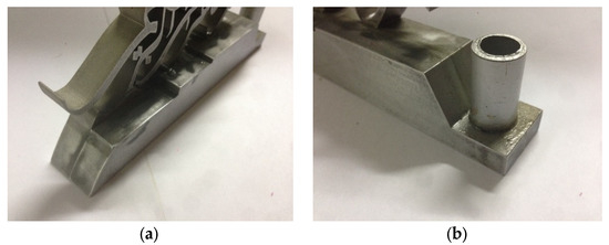
Figure 2.
BISMILLAH calligraphy. (a) Another plate was joined using epoxy; (b) an aluminum rod was joined using epoxy.

Table 1.
Comparison between designed product and machined product for BISMILLAH calligraphy.
3.2. Producing REVERSE ENGINEERING LAB Typography Product
For the second product, the machining process was performed using a CNC 5-axis milling machine. Even though the CNC 5-axis milling machine can produce 3D products, there are also some limitations that the machine cannot overcome, i.e., the machining process involves a small distance in between the materials that the cutting tool cannot move through. A comparison was made to see the difference between the designed product and the machined product as shown in Table 2.
Table 2.
Comparison of the designed product and machined product of REVERSE ENGINEERING LAB typography.
3.3. Comparing Time Consumption
An interview session with a feedback form was conducted with the person who had created the calligraphy by hand. This session intended to record the time taken for the human to craft the calligraphy using the crafting tools compared with the machining process. The time taken to produce the BISMILLAH calligraphy was then compared with this. The result of this session showed that the time taken to produce the same BISMILLAH calligraphy was about three days, from acquiring the metal plate to the end of producing the art. Moreover, this product is usually produced in small numbers.
For the machining process, the time taken for CNC wire cutting to cut the BISMILLAH calligraphy was only 2 h 35 min and 44 s. Meanwhile, the time taken to produce the REVERSE ENGINEERING LAB typography using the CNC 5-axis milling machine was 22 h, finishing the entire cutting process based on the simulation time. Therefore, this shows that this alternative method is successful in reducing the time taken compared to hand crafting. In addition, such products can be produced in large numbers without wasting a lot of time.
3.4. Comparing the Parameters
Based on the process of the reverse engineering technique, the parameters of the machined product were essentially different to that of the existing product. In this comparison, creating the second product was involved the scanning process. Therefore, the product was compared by measuring six distances according to the design requirement, as shown in Figure 3.

Figure 3.
Distances (number 1 to 6) were measured for the comparison.
The distances within the machined product were compared to the crafted clay. Table 3 shows the comparison between six distances, including the differences and the percentage differences, respectively. For the comparison of the parameters, Distance 6 has the highest percentage difference of 25.21%. It is followed by Distance 3, with 14.20%, Distance 5, with 8.50%, Distance 1, with 3.43%, Distance 4, with 0.81%, and Distance 2, with 0.18%.
Table 3.
Distance comparison between machined product and crafted clay.
4. Conclusions
This study has presented an alternative innovative design method for producing 3D calligraphy products rapidly, and provided an impactful solution by utilizing the integrated techniques of reverse engineering and CNC machining. The integrated reverse engineering and CNC machining techniques successfully addressed the relevant drawbacks by reducing the time consumed, and did not require an original drawing or blueprint to produce 3D calligraphy products, namely, BISMILLAH calligraphy and REVERSE ENGINEERING LAB typography. The time taken to produce the BISMILLAH calligraphy product was less than three hours. Meanwhile, the time taken to produce the REVERSE ENGINEERING LAB typography product was less than one day. Both 3D calligraphy products were successfully produced faster than the traditional hand crafting technique. A comparison between the parameters was performed for the second product only, due to the design requirement that compares the machined product and the crafted clay. This shows that, when the second product undergoes the process of reverse engineering, the parameters vary compared to the existing product and within an acceptable range. Therefore, a lot of 3D calligraphy products can be created rapidly for mass production by using the integrated reverse engineering and CNC machining techniques without requiring original drawings or blueprints, so that it can be sustained and will not disappear until restored by future generations.
Author Contributions
Conceptualization, A.A.A.J. and M.S.A.M.; methodology, A.A.A.J. and M.S.A.M.; software, A.A.A.J. and M.S.A.M.; validation, A.A.A.J. and M.S.A.M.; formal analysis, A.A.A.J. and M.S.A.M.; investigation, A.A.A.J. and M.S.A.M.; resources, A.A.A.J. and M.S.A.M.; data curation, A.A.A.J. and M.S.A.M.; writing—original draft preparation, A.A.A.J.; writing—review and editing, M.S.A.M.; visualization, A.A.A.J. and M.S.A.M.; supervision, M.S.A.M.; project administration, M.S.A.M.; funding acquisition, M.S.A.M. All authors have read and agreed to the published version of the manuscript.
Funding
This research was supported by Universiti Sains Malaysia under the Research University Grant (No: 814247).
Institutional Review Board Statement
Not applicable.
Informed Consent Statement
Not applicable.
Data Availability Statement
The datasets presented in this article are not readily available because the data are part of an ongoing study.
Acknowledgments
The authors would like to thank the School of Mechanical Engineering, Engineering Campus, Universiti Sains Malaysia, for supporting this study.
Conflicts of Interest
The authors declare no conflicts of interest.
References
- Othman, R.; Zainal-Abidin, Z.J. The Importance of Islamic Art in Mosque Interior. Procedia Eng. 2011, 20, 105–109. [Google Scholar] [CrossRef]
- Xu, P.; Zheng, X.; Chang, X.; Miao, Q.; Tang, Z.; Chen, X.; Fang, D. Artistic information extraction from Chinese calligraphy works via Shear-Guided filter. J. Vis. Commun. Image Represent. 2016, 40, 791–807. [Google Scholar] [CrossRef]
- French, T.E. Engineering Drawing and Graphic Technology; McGraw-Hill Companies: New York, NY, USA, 1978. [Google Scholar]
- Mills, G.H.; Walter, J.A. Technical Writing; Holt Rinehart & Winston: Austin, TX, USA, 1986. [Google Scholar]
- Brüggemann, J.; Meub, L. Experimental evidence on the effects of innovation contests. Inf. Econ. Policy 2017, 39, 72–83. [Google Scholar] [CrossRef]
- Rasouli, A.; Attaran, M. Improve the Quality of Traditional Education of Calligraphy in Iran by Using of Collaborative e-Learning. Procedia-Soc. Behav. Sci. 2012, 51, 433–443. [Google Scholar] [CrossRef][Green Version]
- Turgut, Ö.P. Calligraphic Forms in Contemporary Typographic Design. Procedia-Soc. Behav. Sci. 2014, 122, 40–45. [Google Scholar] [CrossRef][Green Version]
- Chao, F.; Huang, Y.; Zhang, X.; Shang, C.; Yang, L.; Zhou, C.; Hu, H.; Lin, C.-M. A robot calligraphy system: From simple to complex writing by human gestures. Eng. Appl. Artif. Intell. 2017, 59, 1–14. [Google Scholar] [CrossRef]
- Phang, S.K.; Lai, S.; Wang, F.; Lan, M.; Chen, B.M. Systems design and implementation with jerk-optimized trajectory generation for UAV calligraphy. Mechatronics 2015, 30, 65–75. [Google Scholar] [CrossRef]
- Wang, Z.; Liao, M.; Hagihara, R.; Maekawa, Z. Comparison between Expert and Beginner on Calligraphy Letter’s Characteristic. Procedia Manuf. 2015, 3, 495–502. [Google Scholar] [CrossRef][Green Version]
- Abu Mansor, M.S. Free-form surface models generation using reverse engineering technique—An investigation. In Proceedings of the Malaysian Research Group International Conference 2006, Salford, UK, 19–21 June 2006; pp. 379–385. [Google Scholar]
- Várady, T.; Martin, R.R.; Cox, J. Reverse engineering of geometric models—An introduction. Comput.-Aided Des. 1997, 29, 255–268. [Google Scholar] [CrossRef]
- Dúbravčík, M.; Kender, Š. Application of Reverse Engineering Techniques in Mechanics System Services. Procedia Eng. 2012, 48, 96–104. [Google Scholar] [CrossRef]
- Mohd Tahar, M.Z.A.; Abu Mansor, M.S. Development of a Face Sculpture Prototype Using a Reverse Engineering Technique. In Advances in Manufacturing Engineering; Lecture Notes in Mechanical Engineering; Springer: Berlin/Heidelberg, Germany, 2020. [Google Scholar] [CrossRef]
- Miaoulis, G.; Plemenos, D. Intelligent Scene Modelling Information Systems; Studies in Computational Intelligence; Springer: Berlin/Heidelberg, Germany, 2008; Available online: https://books.google.com.my/books?id=7dxrCQAAQBAJ (accessed on 4 October 2024).
- Sokovic, M.; Kopac, J. RE (reverse engineering) as necessary phase by rapid product development. J. Mater. Process. Technol. 2006, 175, 398–403. [Google Scholar] [CrossRef]
- Abdulqawi, N.I.A.; Abu Mansor, M.S. Preliminary Study on Development of 3D Free-Form Surface Reconstruction System Using a Webcam Imaging Technique. Int. J. Precis. Eng. Manuf. 2020, 21, 437–464. [Google Scholar] [CrossRef]
- Lin, A.C.; Lin, S.-Y. Computer-aided mold engraving: From point-data smoothing, NC machining, to accuracy checking. J. Mater. Process. Technol. 1999, 86, 101–114. [Google Scholar] [CrossRef]
- Anggoro, P.W.; Bawono, B.; Sujatmiko, I. Reverse Engineering Technology in Redesign Process Ceramics: Application for CNN Plate. Procedia Manuf. 2015, 4, 521–527. [Google Scholar] [CrossRef][Green Version]
- Motavalli, S. Review of reverse engineering approaches. Comput. Ind. Eng. 1998, 35, 25–28. [Google Scholar] [CrossRef]
- Abdul Basir, M.H.; Abu Mansor, M.S. Towards Knowledge-Based Computer Aided Process Planning for 5-Axis CNC Machining. In Intelligent Manufacturing and Mechatronics; Lecture Notes in Mechanical Engineering; Springer: Berlin/Heidelberg, Germany, 2024. [Google Scholar] [CrossRef]
- Misman, L.N.; Abu Mansor, M.S. Investigation on Accessible CNC Simulation Approaches for Multi-axis Milling Machining Through CAD/CAM. In Intelligent Manufacturing and Mechatronics; Lecture Notes in Mechanical Engineering; Springer: Berlin/Heidelberg, Germany, 2024. [Google Scholar] [CrossRef]
- Mao, J.; Chen, X.; Feng, W.; Yuan, S.; Du, R. A precision CNC turn-mill machining center with gear hobbing capability. Precis. Eng. 2015, 41, 126–134. [Google Scholar] [CrossRef]
- Zębala, W.; Plaza, M. Comparative study of 3- and 5-axis CNC centers for free-form machining of difficult-to-cut material. Int. J. Prod. Econ. 2014, 158, 345–358. [Google Scholar] [CrossRef]
- Gu, J.; Agapiou, J.S.; Kurgin, S. CNC machine tool work offset error compensation method. J. Manuf. Syst. 2015, 37, 576–585. [Google Scholar] [CrossRef]
- Soori, M.; Arezoo, B.; Habibi, M. Dimensional and geometrical errors of three-axis CNC milling machines in a virtual machining system. Comput.-Aided Des. 2013, 45, 1306–1313. [Google Scholar] [CrossRef]
- Harvey, C.C.; Murray, H.H. Industrial clays in the 21st century: A perspective of exploration, technology and utilization. Appl. Clay Sci. 1997, 11, 285–310. [Google Scholar] [CrossRef]
- Wilson, M. Why The Car Industry Still Builds Life-Size Clay Models. 2015. Available online: https://www.fastcompany.com/co-design (accessed on 4 October 2024).


Disclaimer/Publisher’s Note: The statements, opinions and data contained in all publications are solely those of the individual author(s) and contributor(s) and not of MDPI and/or the editor(s). MDPI and/or the editor(s) disclaim responsibility for any injury to people or property resulting from any ideas, methods, instructions or products referred to in the content. |
© 2025 by the authors. Licensee MDPI, Basel, Switzerland. This article is an open access article distributed under the terms and conditions of the Creative Commons Attribution (CC BY) license (https://creativecommons.org/licenses/by/4.0/).