1. Introduction
According to a report by the National Institute of Statistics and Informatics (INEI), the percentage of people with a permanent disability represents 10.3% of the population in our country. In other words, there are more than 3 million individuals facing permanent limitations to their ability to move, walk, and/or use their arms or legs [
1]. In this regard, the use of support equipment such as crutches or wheelchairs has become crucial for many of these individuals to carry out their daily activities. However, according to the People’s Defender’s Office, 60% of people with such disabilities cannot move freely because the necessary accessibility conditions have not been implemented, as seen in
Figure 1.
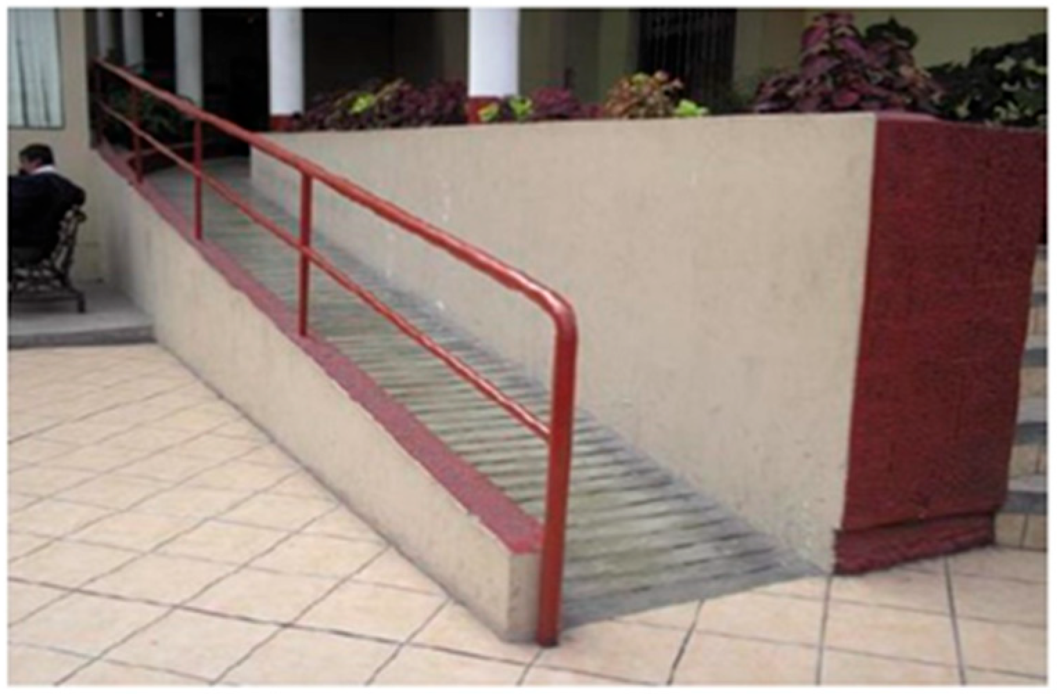
Irregular architecture (see
Figure 1) and ramps with a steep slope (see
Figure 2) are present in many locations in our capital and primarily disadvantage individuals using conventional wheelchairs for mobility. In this sense, the main difficulties faced by these individuals are as follows. Firstly, if they do not have sufficient strength to navigate such irregular terrains, they will need assistance from another person. This significantly limits the time a disabled person can spend moving around, as it depends on the commitment of another individual.
Secondly, since traditional wheelchairs are based on a classic model with two fixed-axis wheels and two swivel-axis wheels (perpendicular to the terrain), their movements are limited, especially in small spaces. Finally, since these wheelchairs are designed to move on completely flat surfaces, navigating irregular terrains can expose users to very strong impacts on their lower limbs or organs located in the abdominal or lumbar region [
3].
2. Proposed Solution
To address the previously described issues, the design of a prototype of an omnidirectional vehicle equipped with a suspension system, capable of mobilizing a person weighing up to 90 kg with lower limb disabilities on irregular and/or narrow terrains, was proposed.
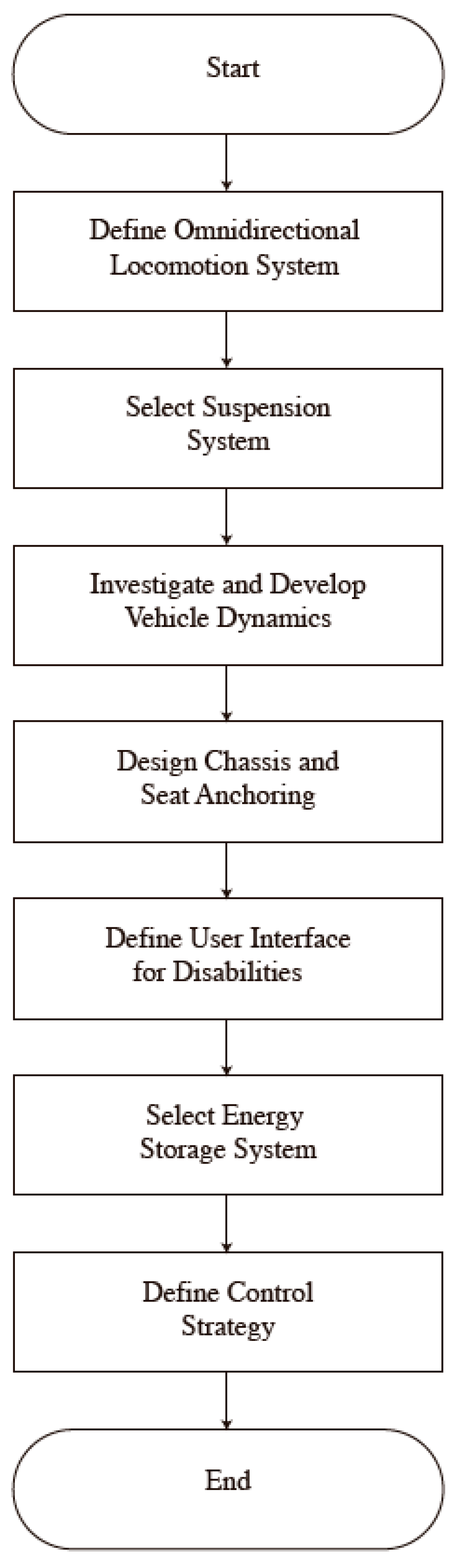
To achieve the described solution, the following flow chart (
Figure 3) shows the specific objectives of this work.
In this regard, the following project requirements are proposed:
The maximum dimensions of the system will be 600 × 900 × 1300 mm.
The system speed should fall within the range of 5–10 km/h.
An omnidirectional locomotion system must be utilized.
The system should be able to support a maximum load of 120 kg.
The system’s autonomy should be within a range of 3–5 h.
The power source for battery recharge must be electric—220 VAC.
The power system must be rechargeable.
It should indicate whether the path to be traversed is safe before proceeding.
There must be speed control for the vehicle.
An emergency shutdown button should be present in case control of the vehicle is lost.
The system should be capable of overcoming obstacles of 50 mm in height and slopes of 10°.
The manufacturing cost of the project should not exceed PEN 5000.
3. Conceptual Design
In this section, the functions that the proposed system will perform to achieve the overall objective will be defined. In this regard, a black box of the global function, the sequence of operations, and the function structure will be developed to illustrate the sequence of partial functions of the system.
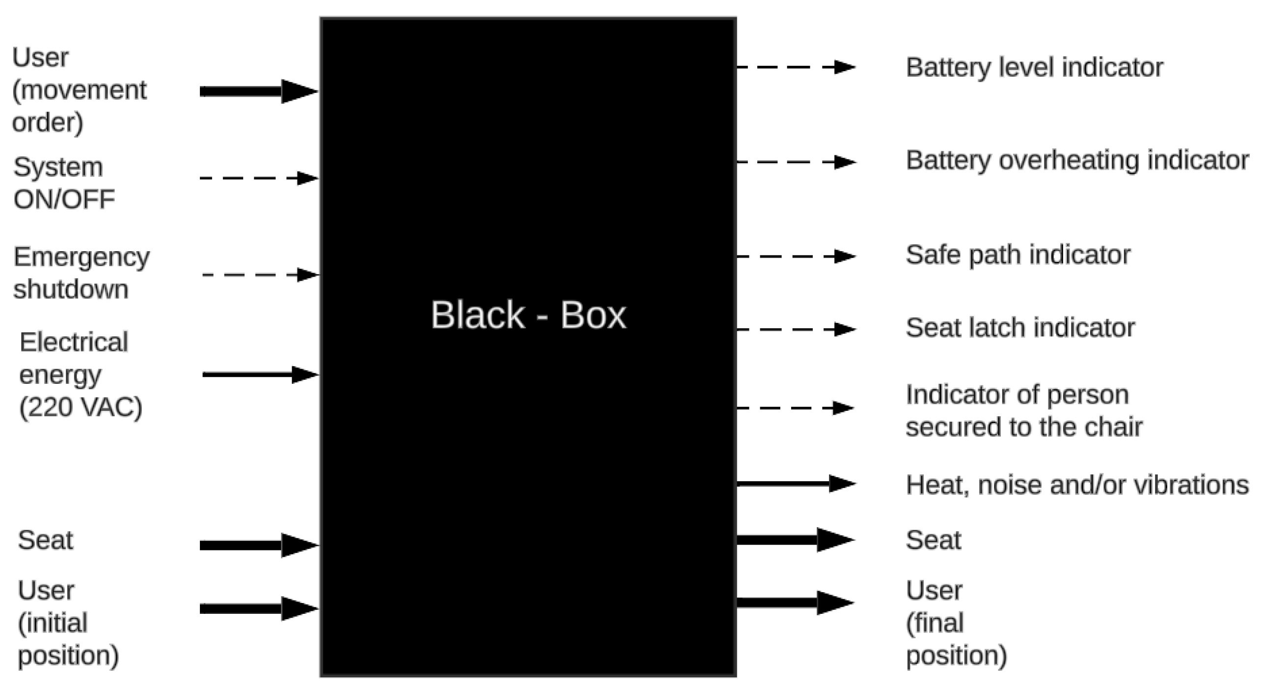
3.1. Black Box
The idea behind a black box abstraction is to identify the inputs and outputs of the system. This can be seen in
Figure 4.
3.2. Sequence of Operations
The user turns on the system and inputs the desired direction of movement using an input peripheral, which is then sent to the controller for processing. Subsequently, the controller determines the rotation direction of each motor to achieve the required movement. Additionally, during the chair’s movement, the suspension system supports the weight of the person and components while maintaining stable displacement on the terrain. Furthermore, the system maps the front path to identify potential hazardous routes, meaning routes that the system cannot overcome. On the other hand, battery level and temperature are measured to determine remaining autonomy and potential overheating, respectively. Finally, the user turns off the system upon reaching their destination or stops it using the emergency button if necessary.
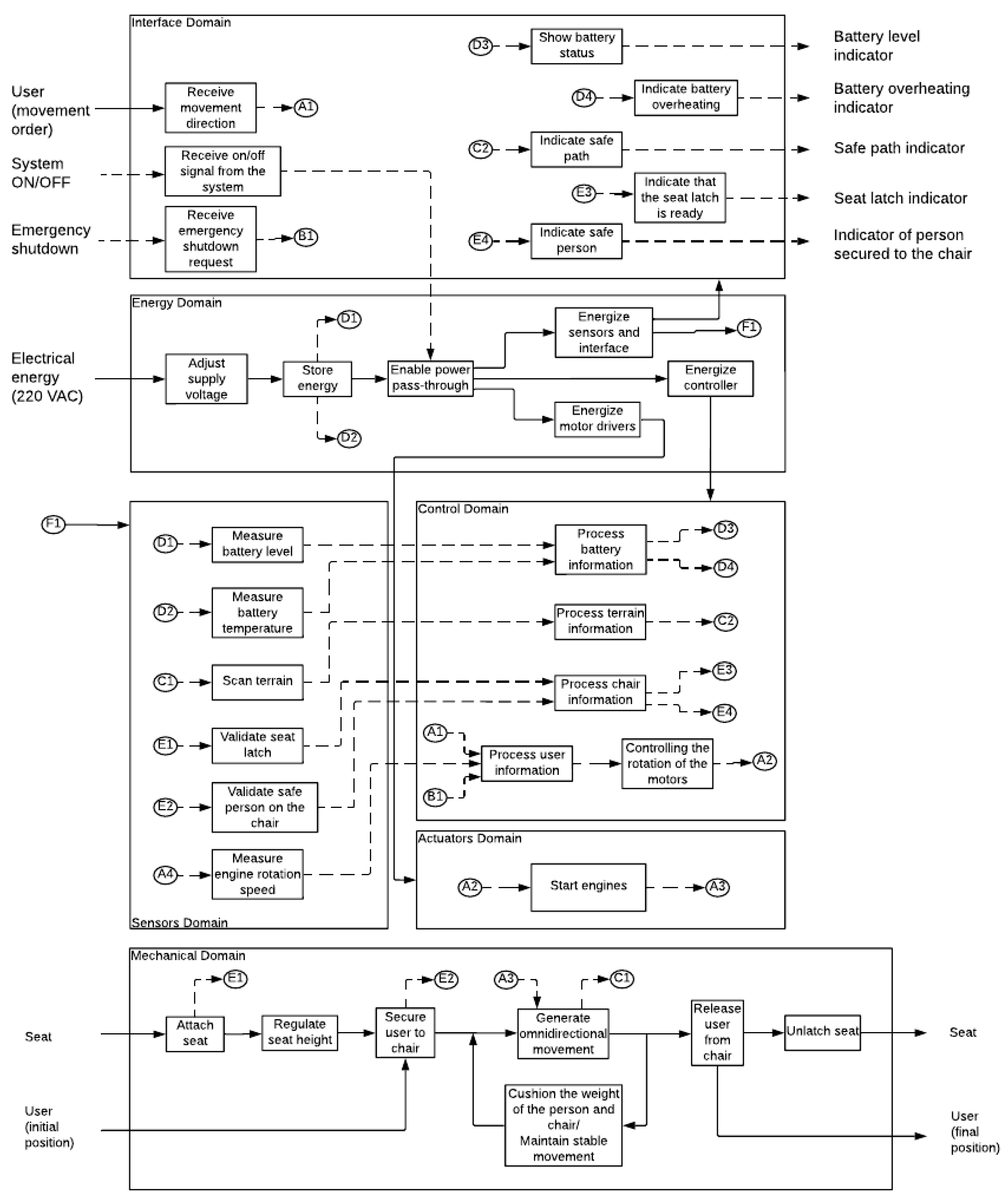
3.3. Function Structure
Based on the black box and the sequence of operations, the function structure is defined to illustrate how the partial functions performed by the system are interrelated. This can be seen in
Figure 5.
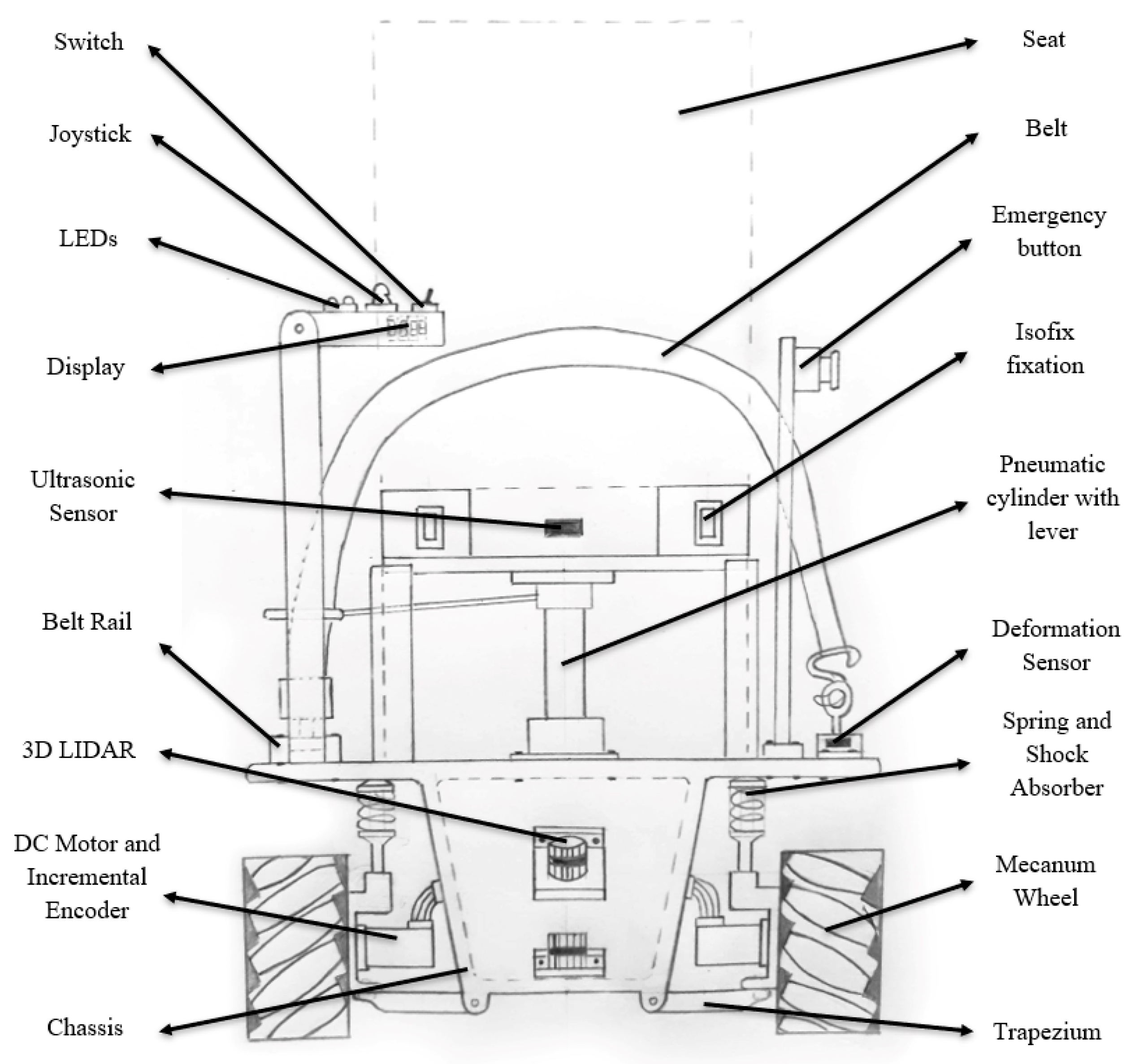
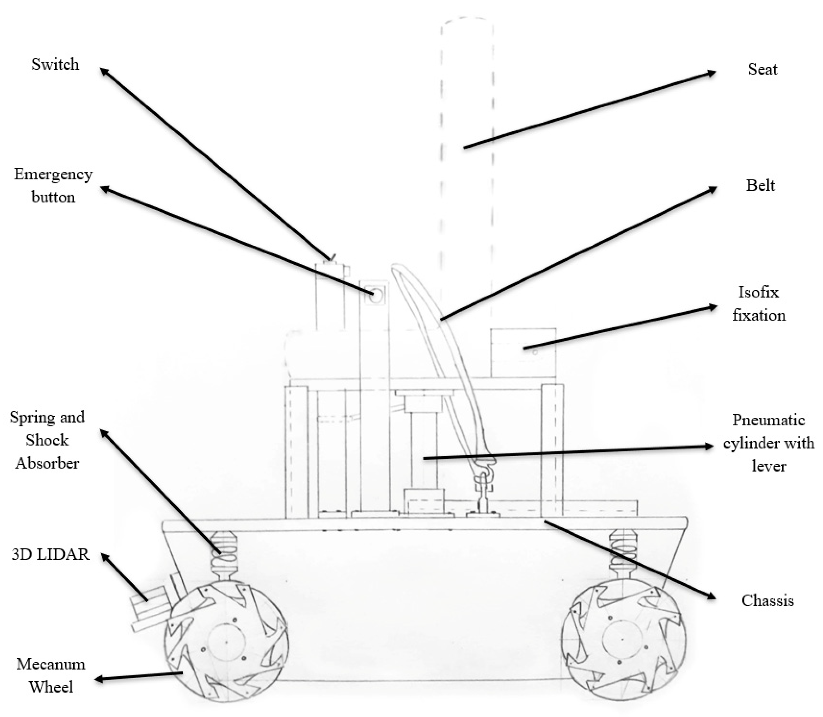
Based on the function structure, the solution concept is defined through a schematic representation of the mechanical components and a diagram of the electronic and control elements. This conceptual design can be seen in
Figure 6 and
Figure 7.
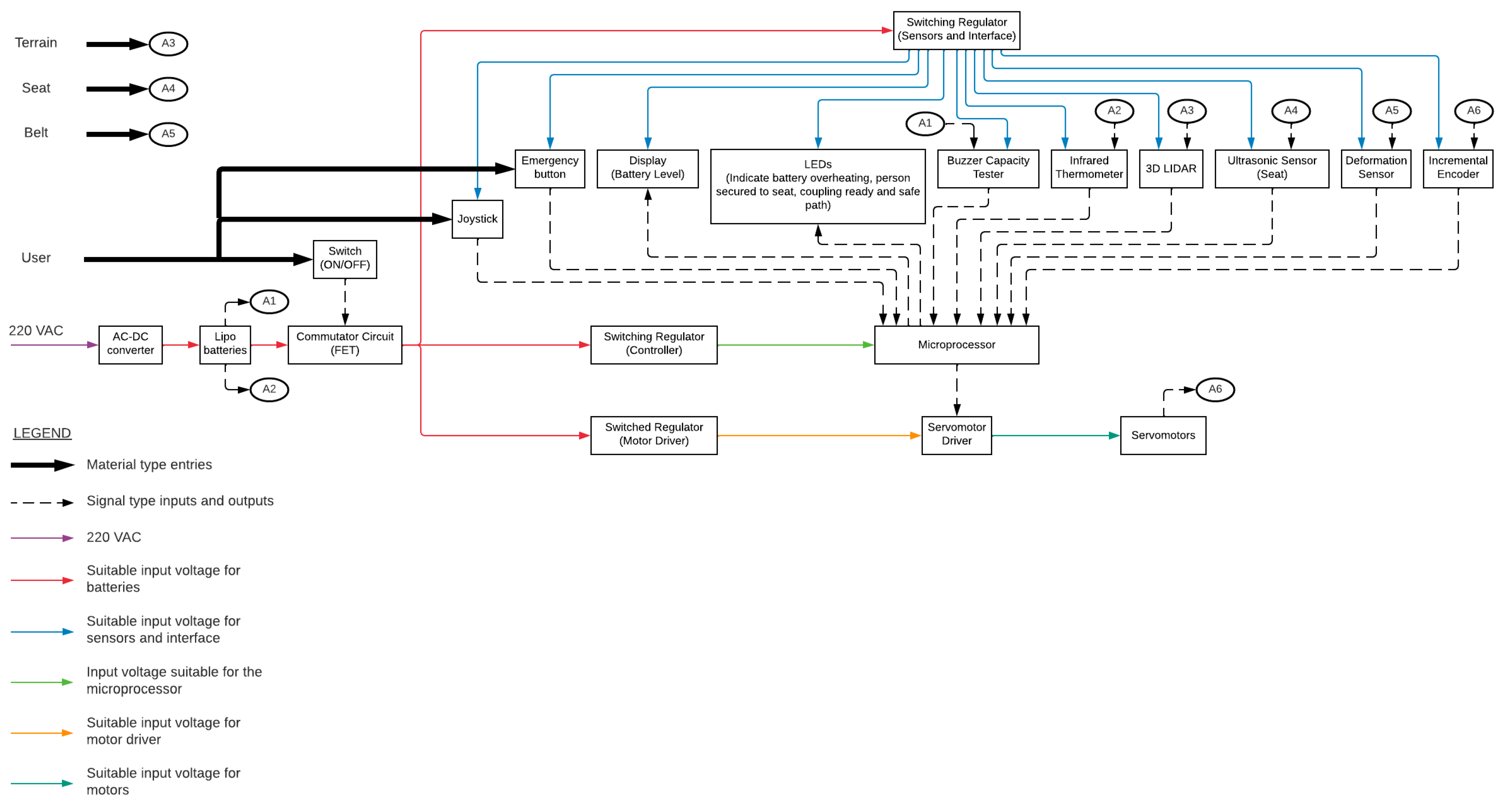
Electronics of the conceptual design were also developed, as shown in
Figure 8.
4. Dynamics of the Final Design
In this section, mathematical models for omnidirectional motion dynamics and the suspension system will be defined to ensure adequate stability. Additionally, relevant calculations and simulations for various test scenarios will be conducted.
4.1. Dynamics
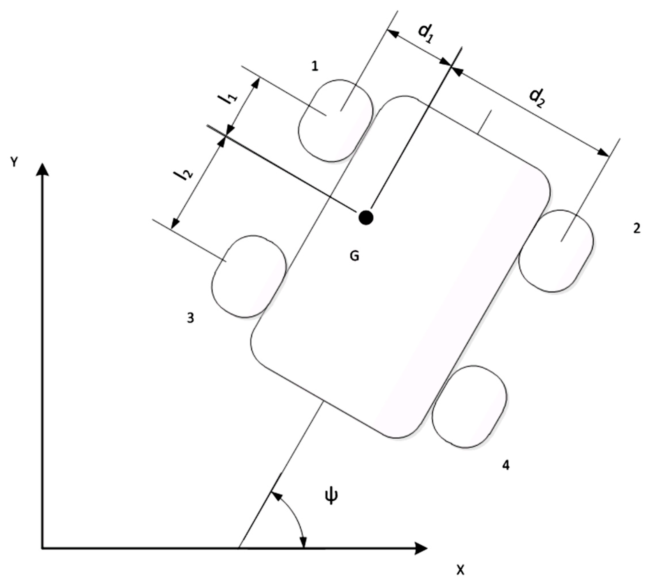
The vehicle dynamics will be defined by the mathematical model shown in
Figure 9.
In this regard, the kinematics of the locomotion system are described by Equation (1) [
4]:
where the following variables are used:
: angular velocity of wheel i;
ψ: orientation of the vehicle in the xy plane;
,: Cartesian velocities of the vehicle’s center of mass (G);
: angular velocity of the vehicle around the z axis;
,: dimensions of the vehicle;
: roller angle i relative to the orientation of the wheel;
: radius of the wheel.
Then, for the kinetics of the vehicle, the following matrix equations will be used [
4]:
Equations (4)–(12) show the expressions for
:
The following variables were considered in the aforementioned equations:
: mass of the vehicle;
: mass of the wheel;
: principal moment of inertia of the vehicle around the z axis;
: principal moment of inertia of a wheel around an axis parallel to the z axis;
: principal moment of inertia of a wheel around its longitudinal axis;
: torque applied to wheel I;
: Lagrange multiplier i.
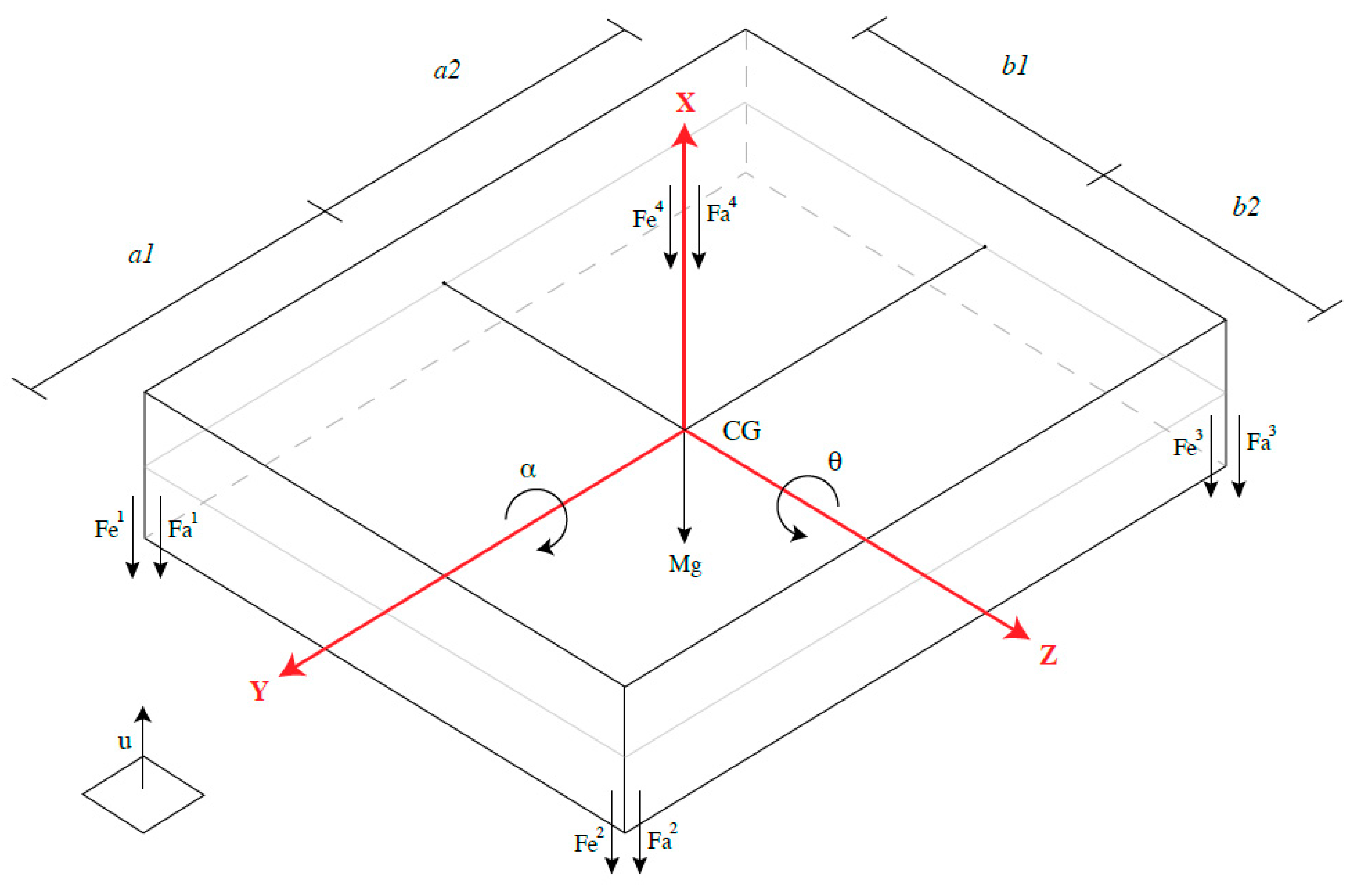
4.2. Suspension System
The suspension system was represented according to the mathematical model in
Figure 10.
The following variables were used to calculate the motion of the vehicle:
: vertical position of the center of mass of the vehicle;
: roll angle of the vehicle;
: pitch angle of the vehicle;
: suspended mass;
: standard Earth gravity;
: elastic force on wheel i;
: damping force on wheel i.
The following change of variables is performed:
Using the Lagrange equations with multipliers, Equations (13)–(18) are acquired:
4.3. Simulation Resuts
4.3.1. Translational and Rotational Motion Simulations
Using Equations (1)–(3), torque data were obtained for a range of motions of the vehicle. This considered the dynamic characteristics of the final design. Results can be observed in
Table 1 and
Table 2.
It was observed that the maximum torque required to move the vehicle is 50.88 N·m. It was also observed that the maximum angular velocity required is 21.20 rad/s. These parameters are crucial to select the appropriate DC motor for the wheelchair.
4.3.2. Simulation of the Suspension System
In this section, the response of the suspension system to different terrains that may be encountered on the path will be evaluated. In this regard, the terrain will be modeled as a sinusoidal function that varies over time and acts on a wheel of the vehicle.
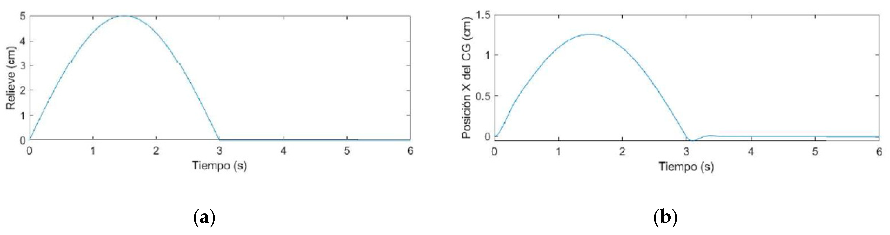
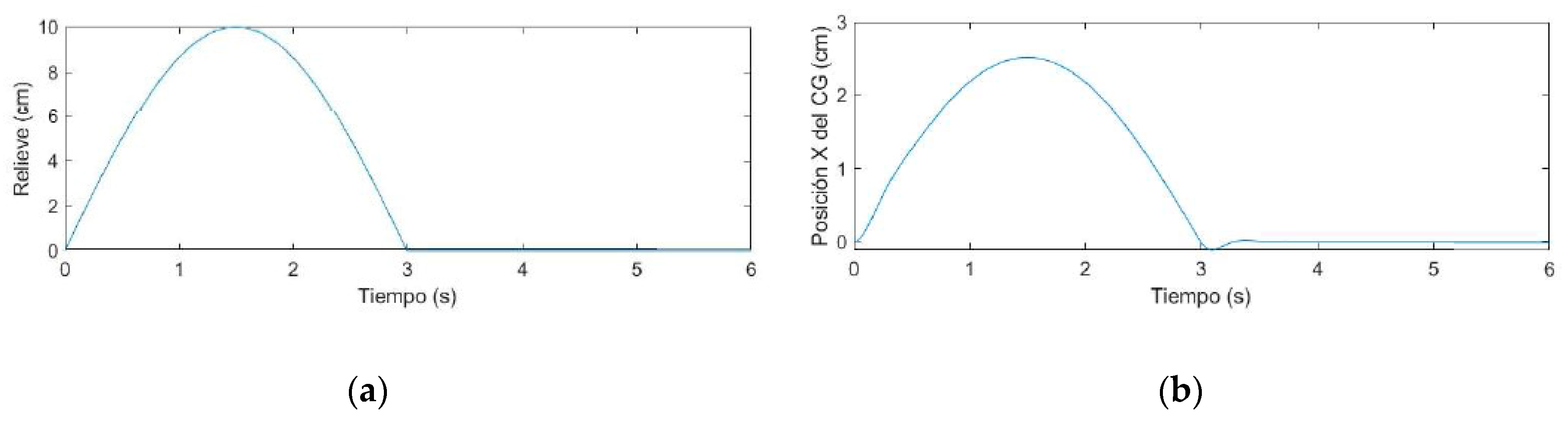
The following
Figure 11,
Figure 12 and
Figure 13 show the response of the
x coordinate (according to the coordinate system shown in
Figure 10) to an input displacement
u on one of the wheels. Numerical values for simulations were based on real suspension systems [
5,
6,
7,
8].
As seen in
Figure 11,
Figure 12 and
Figure 13, the proposed suspension system reduces the amplitude of the original input by 75% and the original position of the center of gravity is restored after less than 0.5 s, having surpassed the obstacle.
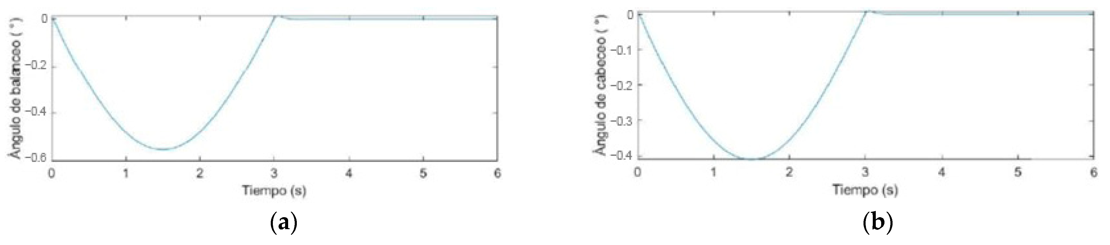
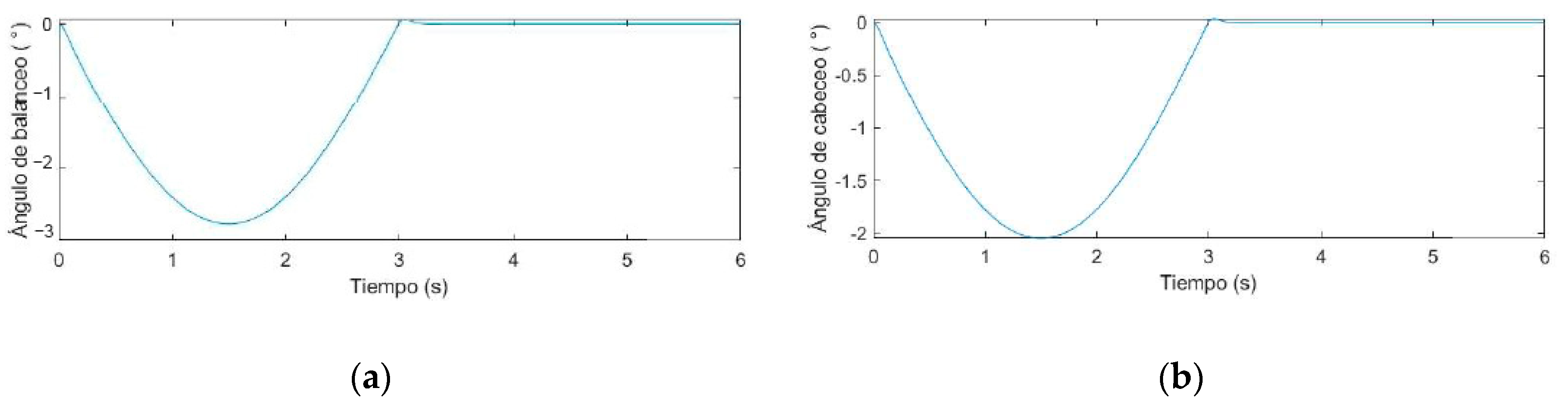
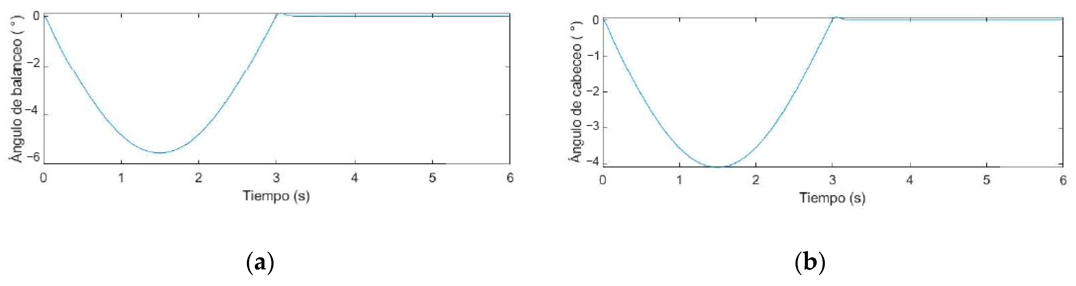
As seen in
Figure 14,
Figure 15 and
Figure 16, the roll and pitch angles are less than 0.6°, which is considerably less than the ones reported with rigid suspension.
5. Conclusions
A rectangular configuration of four Mecanum wheels was chosen for the traction and locomotion system design because it is better suited for outdoor use, providing greater maneuverability on uneven terrains. Additionally, equations of rigid body kinematics and Lagrange equations with multipliers were employed for the dynamic analysis of the vehicle’s motion, allowing for precise modeling of its behavior. Consequently, simulation results for the suspension system indicate a 25% reduction in terrain irregularity amplitudes, thereby improving stability and comfort during driving. Moreover, the study reveals significant findings regarding suspension angles, noting that these angles measure less than 0.6°. This observation contrasts sharply with the higher angles typically reported for rigid suspension systems.
Author Contributions
Conceptualization, P.A.F. and J.L.A.; methodology, P.A.F. and J.L.A.; simulations, J.L.A.; validation, P.A.F. and J.L.A.; formal analysis, P.A.F. and J.L.A.; writing—original draft preparation, J.L.A.; writing—review and editing, P.A.F. and J.L.A.; supervision, P.A.F.; project administration, P.A.F. All authors have read and agreed to the published version of the manuscript.
Funding
This research received no external funding.
Institutional Review Board Statement
Not applicable.
Informed Consent Statement
Not applicable.
Data Availability Statement
Data are contained within the article.
Conflicts of Interest
The authors declare no conflicts of interest.
References
- National Institute of Statistics and Informatics. Censos Nacionales 2017: XII de la Población, VII de Vivienda y III de Comunidades Indígenas; National Institute of Statistics and Informatics: Lima, Peru, 2018. [Google Scholar]
- Defensoría del Pueblo. Barreras Físicas que Afectan a Todos; Report N° 114; Defensoría del Pueblo: Lima, Peru, 2006. [Google Scholar]
- Herrera, P.; Peláez, I.; Ramos, L.; Sánchez, D.; Burgos, R. Problemas con el uso de sillas de ruedas y otras ayudas técnicas y barreras sociales a las que se enfrentan las personas que las utilizan. Estudio cualitativo desde la perspectiva de la ergonomía en personas discapacitadas por enfermedades reumáticas y otras condiciones. Reumatol. Clínica 2013, 9, 24–30. [Google Scholar]
- Flores, P. Modelling, Simulation and Experimental Verification of a Wheeled-Locomotion System Based on Omnidirectional Wheels. Master’s Thesis, Pontifical Catholic University of Peru and Technische Universitaet Ilmenau, San Miguel, Peru, 2016. [Google Scholar]
- Blancarte, J. ¿Cuáles son los Tipos de Suspensión más Comunes? Available online: https://noticias.autocosmos.com.co/2013/08/23/cuales-son-los-tipos-de-suspension-mas-comunes (accessed on 10 February 2021).
- Campos, A. Diseño e Implementación de un Vehículo de Cuatro Ruedas Omnidireccionales. Undergraduate Thesis, Universidad Politécnica de Valencia, Valencia, Spain, 2018. [Google Scholar]
- Cebolla, B. Modelado y Caracterización de Sistemas de Suspensión en Vehículos Automóviles. Undergraduate Thesis, Universidad Politécnica de Valencia, Valencia, Spain, 2017. [Google Scholar]
- Colomer, J. Estudio de los Sensores Para la Detección de Obstáculos Aplicables a Robots Móviles. Master’s Thesis, Universidad Abierta de Cataluña, Cataluña, Spain, 2018. [Google Scholar]
| Disclaimer/Publisher’s Note: The statements, opinions and data contained in all publications are solely those of the individual author(s) and contributor(s) and not of MDPI and/or the editor(s). MDPI and/or the editor(s) disclaim responsibility for any injury to people or property resulting from any ideas, methods, instructions or products referred to in the content. |
© 2025 by the authors. Licensee MDPI, Basel, Switzerland. This article is an open access article distributed under the terms and conditions of the Creative Commons Attribution (CC BY) license (https://creativecommons.org/licenses/by/4.0/).


