Abstract
In this paper, the development of a low-cost acoustic sensor is presented based on an import-substituting element base as a cheap alternative to professional sensors or analog sensors. An Arduino board, a microphone module, a microSD card module, and other modules were used. To improve the accuracy of the data taken from the microphone, it was calibrated using a reference noise meter, using a logarithmic smoothing method to calculate the sound level in decibels, and an equation was formulated for converting the obtained ADC values into decibels. The code of the program executed by the sensor was developed and sewn into the device. The data captured from the microphone are stored in a CSV file with the date and time of the captured data.
1. Introduction
Ambient noise is one of the aggressors in the environment that has a negative effect on the human body. Constant suffering from noise can cause the following consequences [1]:
- Hearing loss or impairment;
- Problems with the cardiovascular system;
- Decreased sleep quality;
- Memory impairment and deterioration of cognitive skills;
- Deterioration of attention and concentration.
In modern society, not enough attention is paid to the problem of the influence of noise and its consequences; therefore, in order to solve this problem, it is necessary to regulate its level and time of exposure. Special measurement methods are used to assess the noise level in various rooms or in an open area. One of the most common methods is the use of sound sensors used at the measurement location. The sensor registers the ambient noise level with a certain frequency using the built-in microphone and displays it on the screen.
Our goal is to simplify this process by eliminating the need for manual measurements. To do this, we have developed an autonomous noise sensor made of components that are easily available in electronics stores and that do not require large material costs. Our sensor will be useful in both enclosed and open spaces, as it has an IP65 protection class. The sensor is easy to assemble; it is convenient to hang it both outside and inside thanks to specially designed fasteners. Moreover, the device’s microphone does not record all the sound and is only used to measure the voltage level on it to obtain the noise level, so it is impossible to receive any confidential data via this sensor.
2. Materials and Methods
2.1. Requirements for Components and Their Selection
Due to our striving to reduce costs, we must define the requirements for the components:
- A motherboard with an integrated microcontroller, supporting plenty of different components and with the ability to write a program using a simple development environment. As a result, we chose the Arduino Uno R3 board (Arduino Software, Turin, Italy), which contains 14 digital and 6 analog pins, which are enough for our project. Also, we can write programs into it with Arduino IDE 2.3.1 (Arduino Software, Turin, Italy), which can be installed on almost any computer;
- A microphone module with an integrated fixed amplifier. It must have the ability to be connected to an Arduino board and have a sensitivity range of 20 Hz–20 kHz. We chose an electret microphone module with a MAX9812L amplifier (Kai Tuo Da, Taipei, Taiwan) with a low quiescent current and a high gain factor of 20 dB;
- A MicroSD card module (Realpoy Electronic Components, China) with the ability to connect to an Arduino board. So, a MicroSD card module with an SPI interface and 5 V supply was chosen;
- For data storage, a MicroSD card (Kingston, Fountain Valley, CA, USA) with a 32 GB volume was chosen;
- A device that can provide current date and time information with ≈1 s accuracy and store that data without any external power supply. As a result, an RTC module based on a DS1302 chip was chosen (Maxim Integrated, San Jose, CA, USA). It has a battery place for independent supply, batteries are at low prices on most markets, and the module has enough accuracy for our project;
- Power supplies for the motherboard with a high capacity and ability to recharge. So, three 18650 format accumulators at 3.7 V 1500 mAh were chosen (Kosmos, Moscow, Russia). With a special battery compartment, they provide ≈ 11.1 V, which is in the required voltage range of an Arduino Uno R3 board through DC input;
- A case for three 18,650 accumulators with a DC output connector (SZEKS, China);
- A case with water and dust resistance. A Gainta G2105 [2] (Gainta, New Taipei City, Taiwan) case was chosen because of its IP65 protection class and dimensions that provide a tight component layout; moreover, it has holes for convenient PCB installation using screws;
- A two-positional key switch with a rubber seal (Ruichi, Shenzhen, China). We chose one with an IP65 protection class;
- A water-resistant and air-transparent membrane (Dixel, Shanghai, China). It provides a hole for the microphone and keeps the water protection class for the case. So, we chose an air-transparent self-adhesive membrane with an IP68 protection class that is used to maintain air pressure in the car’s headlights;
- A printed circuit board measuring 70 × 90 mm (GSMIN, China) to set the RTC and MicroSD modules on it;
- Screws measuring 2 × 6 mm (4 pieces) to fix the printed circuit board;
- Heat shrink tubes—they will provide safe connections between wires;
- The last part of this assembly is wires for part connections. We chose 0.14 copper wire with PVC insulation.
2.2. Electrical Circuit Design
The device’s electrical circuit design is shown in Figure 1. All the components are powered by Arduino’s 5 V pin. Arduino, in turn, is powered by the case with three 18650 accumulators. In this circuit design, seven digital pins and one analog pin were used; so, there are a lot of free pins to use more modules. For example, the NBIoT SIM module can be used to send data to the server by mobile connection.
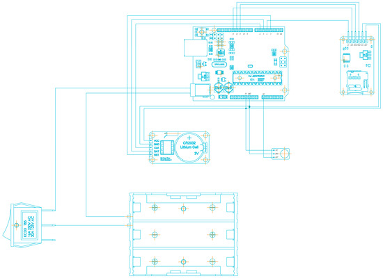
Figure 1.
Electrical circuit design.
It is important to note that there are two states of sensor operations: on and off. The key switch, which is installed in the wire break of the accumulator case, allows us to turn on and off the power supply of the Arduino board. In case the sensor is turned off, all of the components, excluding the RTC module, are deprived of power. This state allows us to save accumulator power while the RTC module keeps renewing time and date data, obtaining power from its cell. So, in case the sensor is turned on, all the parts are given power and the device records noises from the outside.
2.3. Building a Prototype and Writing a Program
After checking the operability of the sensor on the breadboard, the measuring modules were soldered to the Arduino and the printed circuit board using soldering wires. The printed circuit board is located on special racks at the bottom of the case and is attached to it with 2 × 5 mm screws. Holes were drilled and processed in the case for the output of the microphone and the key switch. It is assumed that in preparation for mass production, its own case will be designed with special racks for attaching an Arduino board and a battery compartment to it, as well as with holes for installing a microphone and a switch. A self-adhesive water-resistant membrane is located on the outside of the microphone output hole, and the microphone module and the switch are glued to the housing using sealed BF-2 glue [3]. Device’s layout is shown in Figure 2. The program that the sensor executes is written in the Arduino IDE development environment. The code of the program executed by the sensor was sewn into the device. The data captured from the microphone is stored in a text file with the date and time of the captured data.
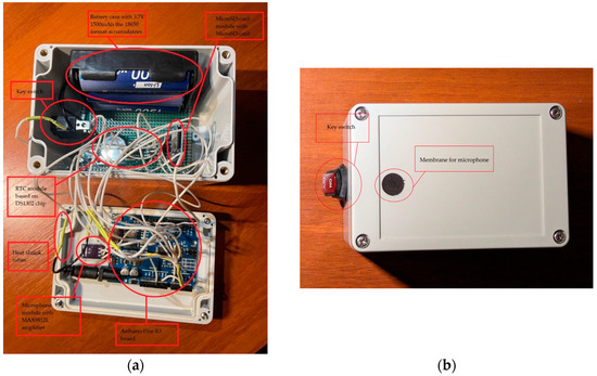
Figure 2.
Device’s components layout. (a) Inner layout; (b) external layout.
3. Results and Discussion
So, we obtained the physical prototype of our device. To improve the accuracy of the data captured from the microphone, the assembled sensor was calibrated. The method for the direct calibration of noise values using a professional noise level meter was used. A noise level corresponding to 39 dB was taken as the level of silence in the laboratory, and a white noise generator was used as the source. As the volume of the noise generated by the generator gradually increased, five values were taken from our sensor and the reference noise meter at each volume level. Thus, 12 experiments were conducted, as a result of which the standard deviations were calculated and a table of correspondence between the readings of the voltage value by microphone and the reference noise meter was obtained. Using the capabilities of MATLAB R2024b (The Mathworks, Portola Valley, CA, USA) the Equation (1) of dB dependence on voltage readings was obtained. Data obtained during the calibration with linearization curve are shown in Figure 3.
dB = 34.2lg(U) + 102.48.
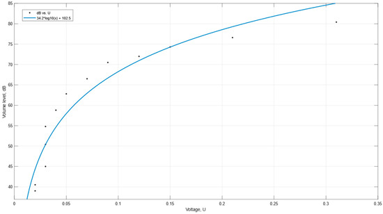
Figure 3.
Graph of linearization of data obtained during calibration.
4. Conclusions
A prototype of the DIY noise sensor was designed for use in production and in the workplace. All available components have been selected for it, and the IP65 dust and moisture protection level has been achieved. Moreover, we performed primary calibrations and achieved results that can be used to increase the sensor accuracy.
The sensor is ready for further improvement, namely the addition of the NB-IoT module, a user interface, easier access to data, the development of its own housing, and eventually, mass production.
One of the key prospects for the further development of the project is to enhance the accuracy and sensitivity of the noise sensor. The sensor is now ready for field testing and the verification of its readings against already calibrated and proven devices.
Also, there is a great perspective for installing a self-developed motherboard with a custom microcontroller and a built-in high-quality microphone that could provide more accuracy and power efficiency.
Author Contributions
Conceptualization, A.V., A.L., and V.M.; methodology, A.L.; software, T.S. and M.N.; validation, A.L., T.G., and T.S.; formal analysis, A.V.; investigation, T.S., T.G., and M.N.; resources, A.V.; data curation, A.V.; writing—original draft preparation, T.S. and M.N.; writing—review and editing, T.S.; visualization, T.S.; supervision, A.V.; project administration, T.S.; funding acquisition, A.V. All authors have read and agreed to the published version of the manuscript.
Funding
This research received no external funding.
Institutional Review Board Statement
Not applicable.
Informed Consent Statement
Not applicable.
Data Availability Statement
The data that support the findings of this study are available from the corresponding author upon reasonable request.
Conflicts of Interest
The authors declare no conflicts of interest.
References
- Seidman, M.D.; Standring, R.T. Noise and Quality of Life. Int. J. Environ. Res. Public Health 2010, 7, 3730–3738. [Google Scholar] [CrossRef] [PubMed]
- G2105—Sealed Enclosure Gainta. Available online: https://www.gainta.com/en/g2105.html (accessed on 21 September 2024).
- GOST 12172—2016 Phenolopolyvinyl Acetate Adhesives Technical Conditions. Available online: https://files.stroyinf.ru/Data2/1/4293747/4293747410.pdf?ysclid=m1dw7peamh381286498 (accessed on 10 September 2024).
Disclaimer/Publisher’s Note: The statements, opinions and data contained in all publications are solely those of the individual author(s) and contributor(s) and not of MDPI and/or the editor(s). MDPI and/or the editor(s) disclaim responsibility for any injury to people or property resulting from any ideas, methods, instructions or products referred to in the content. |
© 2024 by the authors. Licensee MDPI, Basel, Switzerland. This article is an open access article distributed under the terms and conditions of the Creative Commons Attribution (CC BY) license (https://creativecommons.org/licenses/by/4.0/).