Abstract
The full-scale aircraft fatigue test is a critical assessment and validation of the fatigue and damage tolerance design of new aircraft models, and it is also a prerequisite for obtaining the type certification for an aircraft. The full-scale fatigue test is an extremely complex and high-risk task that requires a lengthy period of time and significant financial investment. Therefore, there is an urgent need to shorten the test cycle and safely and efficiently complete the full-scale fatigue test during aircraft model development. Based on the experience and results of a nearly decade-long full-scale fatigue test conducted on a certain civil aircraft, and with reference to the full-scale fatigue test of the Boeing 777 in the United States, this article compares and contrasts the similarities and differences in aircraft configuration, test load spectrum, load application methods, and test detail control, as well as damage detection, monitoring, and maintenance. It analyzes the main reasons for the high time consumption and low efficiency of full-scale fatigue tests for domestic civil aircraft and proposes test acceleration schemes to further shorten the test cycle. The analysis results presented in this article provide valuable reference for the design of full-scale fatigue tests and relevant test personnel.
1. Introduction
Full-scale fatigue testing is a common challenge in the aviation industry worldwide, characterized by high risk, complexity, expense, and time consumption. Reducing the test cycle and improving test efficiency have been common goals in the development of new aircraft models globally. However, the issue of low efficiency in domestic full-scale fatigue tests remains unresolved. This paper analyzes the experiences of a domestic civil aircraft fatigue test, comparing it with the Boeing 777 fatigue test to propose effective acceleration schemes for full-scale fatigue tests.
2. Overview of the Full-Scale Fatigue Test
The full-scale fatigue test, following the full-scale static test, simulates the application of real flight loads (including ground taxiing, takeoff, cruise, descent, and landing, with varying loads distributed across various sections and mission phases, compiled into a ground-air-ground spectrum and cycled repeatedly) within the limits of the design loads [1,2]. This test involves the repeated application of loads to the structure through control systems, hydraulic systems, pneumatic systems, and various complex load-transferring components, with a total number of takeoffs and landings typically exceeding 100,000 cycles. Additionally, factoring in the time required for non-destructive testing, damage repair, equipment calibration, and maintenance, the typical test cycle can span several years, or even decades. Therefore, full-scale fatigue testing is one of the most costly projects in the development of new aircraft models.
3. Differences Between Domestic Civil Aircraft and Boeing 777 Full-Scale Fatigue Tests
3.1. Test Aircraft Physical Parameters and Support Conditions
- Domestic Civil Aircraft: Wingspan of 29.2 m, fuselage length of 24.7 m. It is suspended in the air and supported by a one-piece frame-loading device, along with the forward main landing gear and supporting fixtures.
- Boeing 777: Wingspan of 60.9 m, fuselage length of 63.7 m, placed on an outdoor test platform supported by front and main landing gears [3].
3.2. Test Aircraft Configuration
The primary common features of the experimental aircraft configurations are the absence of high loads and the lack of an integrated flight control system. This allows for specific test conditions that focus on other aspects of aircraft performance and durability.
- Domestic Civil Aircraft Configuration:
- Removal of the nose cone, ailerons and wing tips, landing gear doors, nacelle cowls (front and rear), rudder and wing tips, elevator, and wing tips.
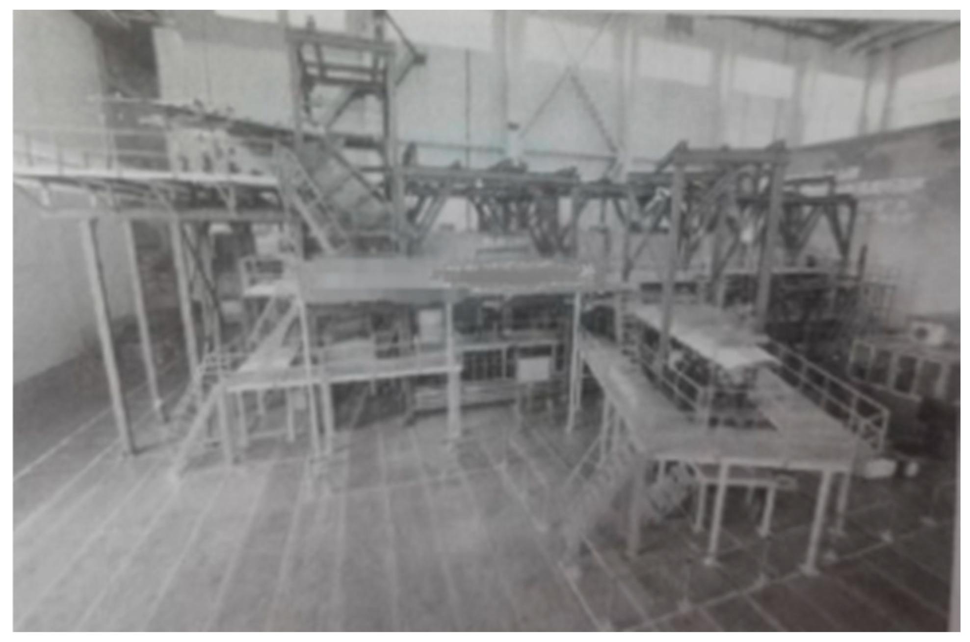
- Use of dummy components: old front landing gear and dummy wheels, dummy main landing gear and dummy wheels, and dummy engines on both sides. Figure 1 refers to a photograph of the civil aircraft fatigue test configuration.
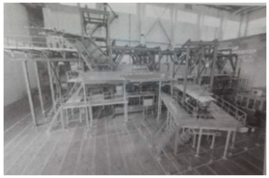 Figure 1. A photograph of the civil aircraft fatigue test configuration.
- Boeing 777 Configuration:
- Removal of the inner flaps, ailerons, and spoilers on the right wing; all fairings removed, retaining cabin floor, cargo floor, and slide rails.
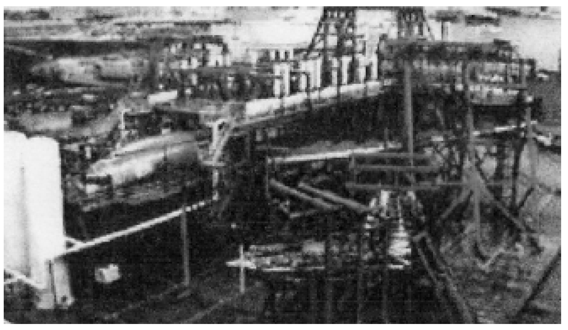
- Use of dummy components: simulated balance control surfaces on the left wing, simulated horizontal stabilizers, and dummy engines on both sides [4]. Figure 2 refers to a photograph of the Boeing 777 fatigue test configuration.
 Figure 2. A photograph of the Boeing 777 fatigue test configuration.
3.3. Test Load Spectrum
The load spectrum is a crucial factor in determining the test rate. The load spectrum realistically simulates the takeoff-taxi-landing process, divided into five types and five levels of loads, cyclically applied to form a 5 × 5 spectrum. The occurrence of the two types of full-aircraft flight and their corresponding frequencies in each spectrum block is shown in Table 1 and Table 2.

Table 1.
Flight types and counts in one cycle block (3000 times) of the domestic civil aircraft.
Table 2.
Flight types and counts in one cycle block (5000 times) of the Boeing 777 [5].
3.4. Load Application Methods
The loads on the load spectrum are applied to the force transmission mechanism and then to the airframe structure through the control system.
A civil aircraft utilizes 98 actuators, transmitting loads through various force transmission methods, such as cables, force-dividing levers, steel plates, screws, clamping plates, etc. The external surface applies loads to the airframe skin through adhesive tapes, tension–compression pads, etc. The pneumatic load is pressurized to 0.029 MPa through 3 pneumatic holes.
The Boeing 777 test aircraft, due to being disassembled and utilizing numerous simulated balancing structural components, has many load-bearing structures removed. Loads are directly applied to the main load-bearing structure through only 100 actuators and fixtures. A total of 62 pneumatic holes are equipped, with a pneumatic pressure of 0.059 MPa. While the main structure is undergoing testing, the simulated components are separately subjected to a fatigue test [6,7].
3.5. Monitoring, Inspection, and Repair
3.5.1. Damage Monitoring
The universal approach to monitoring the structural balance and fatigue damage of experimental aircrafts involves strain monitoring, collecting strain variation data, and establishing a mapping relationship between strain and damage. When cracks initiate or propagate in a structure with strain gauges attached, the local strain experiences an increase or a decrease. When this change reaches a certain threshold value and strain abnormalities occur with a certain frequency, it indicates that cracks are likely to occur in that area, providing a basis for directional localization of cracks and damage [8,9]. A certain civil aircraft utilizes a total of 3264 strain gauges and several acoustic emission probes, while the Boeing 777 aircraft uses 1450 strain gauges. During the 100,000 takeoff–landing fatigue test of the civil aircraft, over 700 cracks were identified, most of which were discovered through time-consuming and labor-intensive visual inspections. Therefore, strain monitoring played a minimal role in detecting and identifying cracks during the test. This is due to several reasons: firstly, the volume of monitoring data is enormous, making it difficult to screen and identify; secondly, there was a lack of effective coordination and communication between personnel collecting strain data and personnel detecting damage.
3.5.2. Inspection and Repair
A civil aircraft undergoes inspections at four different levels. Level 1 involves daily inspections during downtime, Level 2 inspections occur after every 2500 takeoffs and landings, Level 3 inspections take place after every 5000 takeoffs and landings, and Level 4 inspections, which involve removing some loading equipment and opening up parts of the structure for detailed examination, occur after every 25,000 takeoffs and landings. As the inspection level increases, the number of key inspection areas also increases, with more detailed inspections and more inspection methods employed.
The Boeing 777 aircraft undergoes continuous visual inspections combined with strain monitoring, and non-destructive testing methods are used for suspected areas. Areas that have already incurred damage are monitored and inspected daily, and a comprehensive inspection of the aircraft is conducted every time the aircraft reaches its life cycle.
3.6. Test Duration and Completion Status
Table 3 shows the minimum service targets set for the two testing machines, the number of test cycles that must be finally completed, and the duration of the tests.
Table 3.
Comparison of test duration between domestic civil aircraft and Boeing 777.
4. Result Analysis
4.1. Test Aircraft Configuration Analysis
The fatigue test of a civil aircraft is a coordinated test for the entire aircraft, which is realistic, intuitive, and more credible. With multiple loading points and diverse force transmission components, there are significant displacement differences among various components of the aircraft, making it difficult to achieve rapid synchronization of loads. In contrast, the Boeing 777 full-scale aircraft, under the permission of airworthiness, maintains its primary load-bearing structure while simplifying the test aircraft structure through disassembly and simulated balancing. This approach effectively addresses the impact of outdoor environmental factors and successfully applies loads to the full-scale aircraft using only 100 actuators. Fewer loading points and simpler force transmission components make it easier to achieve rapid synchronization.
4.2. Load Spectrum Analysis
Both aircraft use a general 5 × 5 load spectrum, but the domestic aircraft’s spectrum includes a 5% A-class training flight spectrum, which does not significantly impact the loading rate. Therefore, load spectrum differences are not the primary reason for the test rate difference.
4.3. Monitoring, Inspection, and Repair Analysis
During test, the Boeing 777 aircraft effectively utilizes strain monitoring on its primary structure, making inspections more targeted and eliminating the need for frequent downtime inspections. While a civil aircraft boasts more monitoring methods and points, it lacks discernibility in strain or acoustic emission data analysis, and it fails to effectively integrate these data with damage alerts and inspections, resulting in somewhat blind and time-consuming inspections. This civil aircraft typically requires daily downtime inspections, which not only involve checking for aircraft damage but also involve inspecting and replacing broken cables, adhesive tapes, and bolts, a time-consuming process. Both test aircrafts undergo maintenance work according to the maintenance manuals provided by the aircraft manufacturers.
5. Conclusions
This paper analyzes the similarities and differences between the fatigue tests conducted on a domestic civil aircraft and the Boeing 777 full-scale aircraft. The domestic civil aircraft testbed represents a true full-scale aircraft, making the test more intuitive and the results more realistic. In contrast, the Boeing 777 testbed utilizes numerous simulated balance components approved by airworthiness regulations and removes many non-primary load-bearing components, streamlining the load spectrum program and reducing test steps. However, the authenticity and accuracy of the strength, stiffness, and boundary data of the simulated components’ connections with the aircraft body require simulation design and computational capabilities. The control and power systems of the domestic civil aircraft test are not significantly different from those of the 777, but even slight increases in speed lead to deviations in the aircraft’s attitude, primarily due to the lack of synchronized load application. Differences in synchronization among the electro-hydraulic systems and the various force transmission components lead to variations in stroke and response speed among the actuators. Additionally, details, such as actuator quality, servo valve stability, hydraulic oil cleanliness, and temperature control, cannot be overlooked. By further establishing a relationship between strain data and damage mapping and effectively resolving the separation and discrimination of damage waves and other noise waves in acoustic emission monitoring [10], inspections can become more scientific and targeted, reducing the time spent on blind downtime inspections. Even if the design cannot be extensively disassembled like Boeing aircraft, modifying the load transmission method and strictly controlling other details can significantly shorten the test cycle of civil aircraft.
The main factors that affect the test rate can be summarized as follows:
- The test aircraft is overly complete, resulting in an excessive number of load application points for non-primary load-bearing structures, which makes the data for load spectrum control operations more voluminous.
- The diverse methods of load transmission lead to varying actuator strokes, making it difficult to synchronize loads.
- Issues related to detailed control, such as the stability of solenoid valves, the manufacturing quality of actuators, the cleanliness and temperature of hydraulic oil, etc.
- Strain monitoring does not provide guidance or hints for damage inspection, leading to blindness in detection.
Through a comparative analysis of the full-scale fatigue tests of the two aircraft models, this paper proposes methods to accelerate the full-scale fatigue test, which provides valuable insights for aircraft test design, damage detection, and monitoring.
Funding
This research received no external funding.
Institutional Review Board Statement
Not applicable.
Informed Consent Statement
Not applicable.
Data Availability Statement
Data are contained within the article.
Conflicts of Interest
The author is employed by the Aircraft Strength Research Institute of China. The author declares that the research was conducted in the absence of any commercial or financial relationships that could be construed as a potential conflict of interest. The China Aviation Indus-try Corporation had no role in the design of the study; in the collection, analyses, or interpretation of data; in the writing of the manuscript, or in the decision to publish the results.
References
- Zhang, L. Discussion on Several Issues in Whole-Aircraft Fatigue Testing. Adv. Aeronaut. Sci. Eng. 2024, 26, 2–3. (In Chinese) [Google Scholar]
- Pei, L.; Wang, Y.; Zhang, J.; He, X.; Huang, B. Overview of the Development of Whole-Aircraft Fatigue Testing Technology for Fighter Aircraft. Adv. Aeronaut. Sci. Eng. 2023, 14, 137. (In Chinese) [Google Scholar]
- Federal Aviation Regulation Part 25—Airworthiness Standards: Transport Category Airplanes. In Code of Federal Regulations; National Archives and Records Administration: College Park, MD, USA, 2010.
- FAA. AC 25.571—1D, Damage Tolerance and Fatigue Evaluation of Structure; Federal Aviation Administration: Washington, DC, USA, 2011. [Google Scholar]
- Seidel, B.W. 777 Full-Scale Static and Fatigue Structural Tests; Boeing Airliner Magazine: Seattle, WA, USA, 1995. [Google Scholar]
- Fawcett, A.; Trostle, J.; Ward, S. 777 Empennage Certification Approach. In Proceedings of the 11th International Conference on Composite Materials, Gold Coast, Australia, 14–18 July 1997. [Google Scholar]
- Erjian, S. Full-Scale Fatigue Testing of Civil Aircraft Structures. Civ. Aircr. Des. Res. 2012, 104, 49. (In Chinese) [Google Scholar]
- Chai, D.; Guo, X.; Yang, D. Research on Abnormal Data Judgment Method in Whole-Aircraft Fatigue Testing. Eng. Test. 2019, 59, 22–23. (In Chinese) [Google Scholar]
- An, G.; Wang, X.; Du, Z. Application of Applied Data in Fatigue Crack Detection of Aircraft Structures. Struct. Strength Res. 2010, 39, 14–19. (In Chinese) [Google Scholar]
- Yang, Y.; Wang, B.; Qi, X. Acoustic Emission Monitoring Technology for Fatigue Test of Full-Scale Civil Aircraft Structure. Acta Aeronaut. Et Astronaut. Sin. 2022, 43, 241–253. (In Chinese) [Google Scholar]
Disclaimer/Publisher’s Note: The statements, opinions and data contained in all publications are solely those of the individual author(s) and contributor(s) and not of MDPI and/or the editor(s). MDPI and/or the editor(s) disclaim responsibility for any injury to people or property resulting from any ideas, methods, instructions or products referred to in the content. |
© 2025 by the author. Licensee MDPI, Basel, Switzerland. This article is an open access article distributed under the terms and conditions of the Creative Commons Attribution (CC BY) license (https://creativecommons.org/licenses/by/4.0/).