Abstract
Hover-capable unmanned aerial vehicles (UAVs), including rotary-wing UAVs such as unmanned helicopters, multi-rotor drones, and tilt-rotor UAVs, are widely employed due to their hovering capabilities. In recent years, tilt-rotor aircraft, which offer both vertical takeoff and landing as well as rapid maneuverability, have increasingly become a research focus. This paper first proposes a design concept for a flying-wing configuration tilt-rotor tri-rotor UAV, detailing the selection of airfoils and the calculation of aerodynamic parameters. To address the specific operational requirements and flight characteristics of this UAV, a specialized tilting mechanism was developed, and a flight control system was designed and implemented using classical PID control methods. Finally, a prototype of the tilt-rotor tri-rotor UAV was fabricated and subjected to flight tests. The results from both simulations and flight tests confirmed that the UAV met the design performance criteria and that the control method was effective.
1. Introduction
Tilt-rotor unmanned aerial vehicles (UAVs) represent a novel class of hybrid aircraft, integrating the benefits of both helicopters and fixed-wing aircraft [1,2,3,4]. This design merges the vertical takeoff and landing (VTOL), hovering capabilities, and superior low-altitude, low-speed maneuverability of helicopters with the high-speed cruising performance characteristic of fixed-wing aircraft. The cruise speed of tilt-rotor UAVs is two to three times that of conventional helicopters, and their operational range is approximately three times greater [5]. When the rotor nacelle is positioned at 0°, the tilt-rotor UAV functions like a standard multi-rotor UAV, capable of vertical takeoff, hovering, lateral flight, and even inverted flight maneuvers. Conversely, when the rotor nacelle is tilted forward to 90°, the tilt-rotor UAV transitions to a fixed-wing configuration, significantly enhancing its endurance and expanding its operational flight envelope.
The world’s first tilt-rotor aircraft, the XV-3, was developed by Bell Aircraft in the 1940s. Building on this, Bell and Boeing jointly developed the V-22 “Osprey” tiltrotor aircraft [6]. Later, South Korea and Israel also initiated research on tilt-rotor aircraft, successfully developing models such as the V-247 and TR60 [7]. Since the start of the 21st century, significant progress has been made in tilt-rotor research in China. Beihang University designed a tri-copter with six rotors and has developed four iterations [8]. Nanjing University of Aeronautics and Astronautics has conducted extensive research in control design and prototype development [9,10,11,12]. Sichuan AOSSCI Co., Ltd. has introduced several tilt-rotor UAV models and has participated in critical missions, including earthquake relief operations. While there have been notable research advances in quad-rotor tilt-rotor UAVs, studies on tri-copter tilt-rotor UAVs remain relatively scarce.
Compared to tilt-rotor dual-rotor, and quad-rotor drones, tilt-rotor tri-copter drones occupy less ground area at the same weight, making them ideal for carrier operations. Furthermore, tilt-rotor tri-copters are lighter than their quad-rotor counterparts, exhibiting reduced overall energy consumption and longer endurance. Given these advantages, the application prospects for tilt-rotor tri-copters are extensive. This paper presents the design of a flying-wing configuration tilt-rotor tri-copter drone and details the overall design, airfoil selection, aerodynamic analysis, and control system development, culminating in the successful flight testing of the prototype.
2. Overall Design Scheme of UAV
This paper establishes the performance characteristics and key parameters of the tilt-rotor tri-copter using selected parameters from existing tilt-rotor drones, as summarized in Table 1.

Table 1.
Parameters estimated by experience formulas and statistical data.
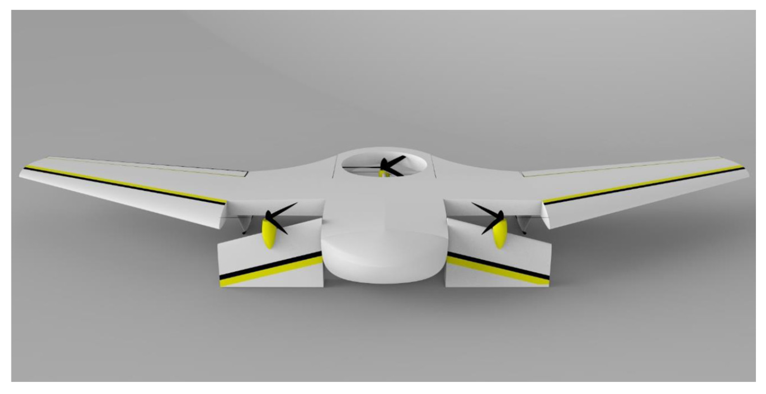
The tilt-rotor drone is designed with a tri-copter configuration, incorporating a tilting rotor on each side of the wings and a ducted fan at the rear of the fuselage to counterbalance torque during hovering. Two carbon fiber rods transmit bending moments from the wings to the fuselage structure. The front and rear beams act as the main load-bearing structures, while two ailerons are installed at the rear of the wings. Additionally, the two vertical tail fins serve the purpose of landing gear. A schematic diagram of the overall layout is presented in Figure 1.
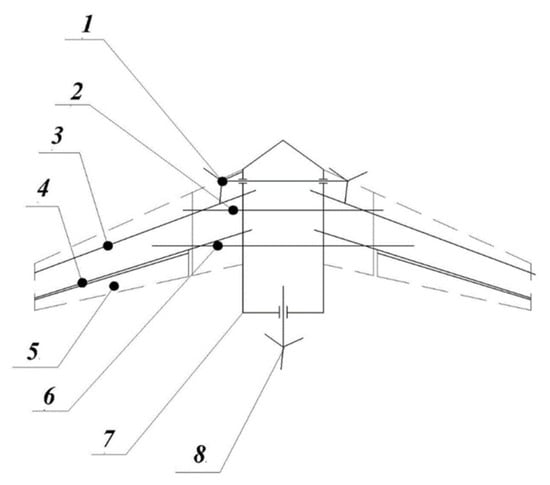
Figure 1.
Schematic diagram of mechanism.
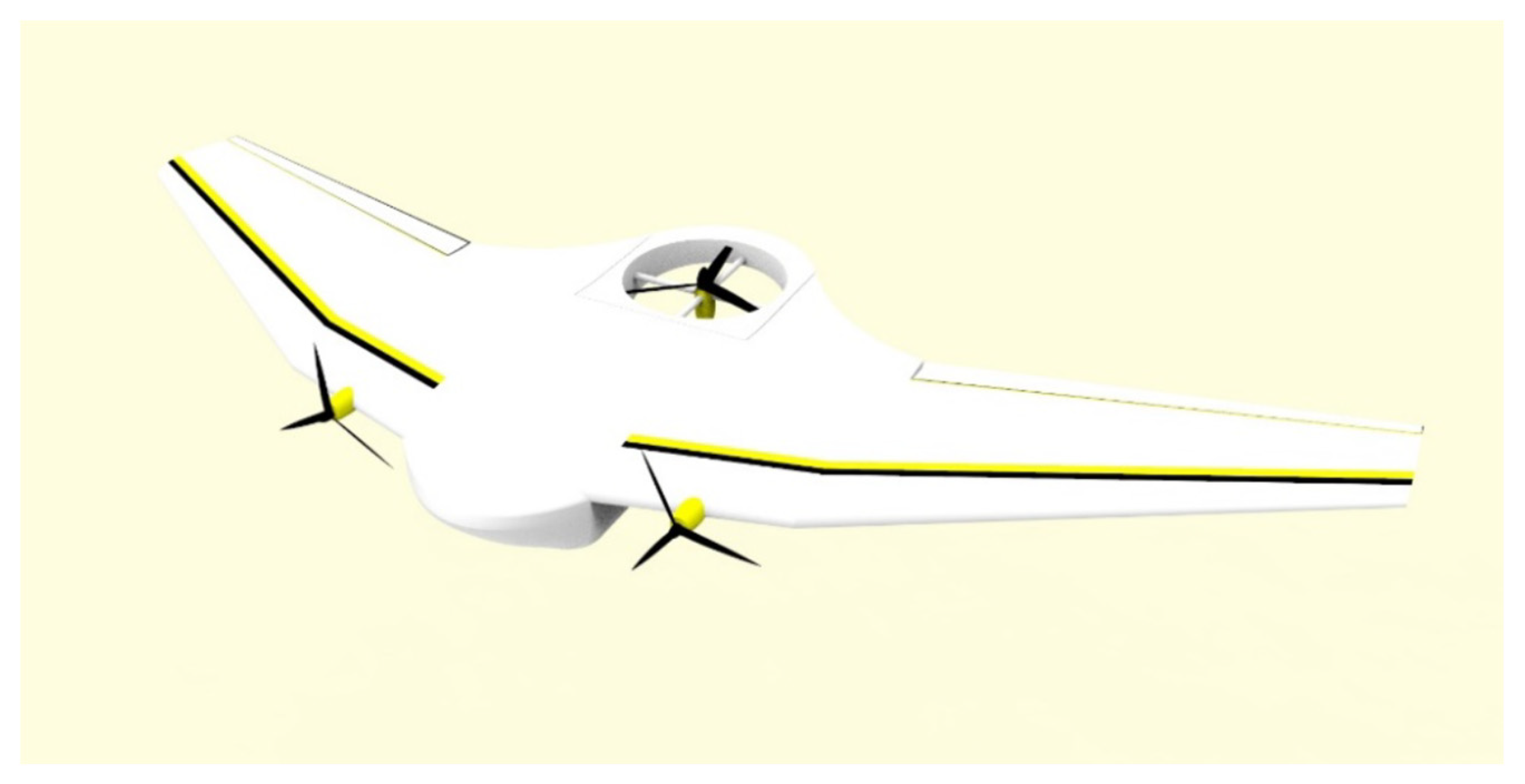
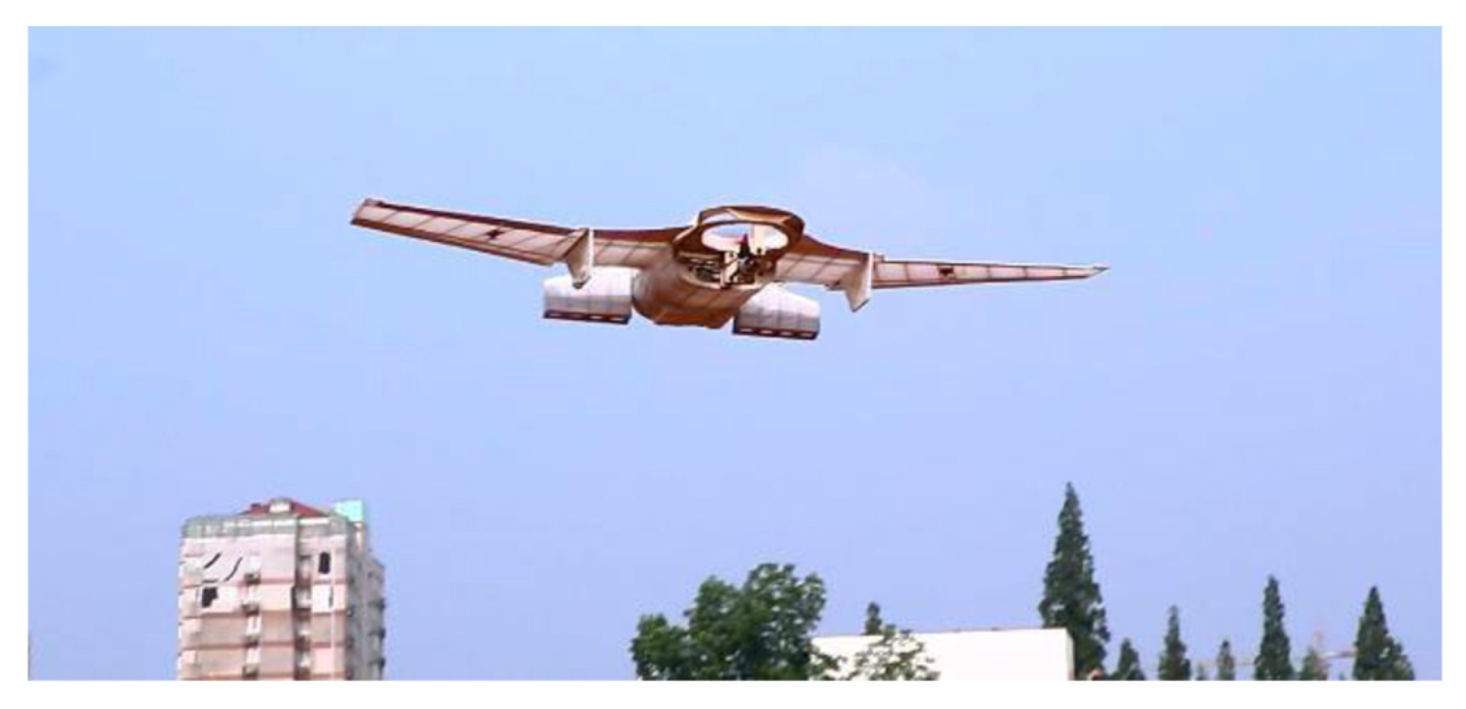
In Figure 1, numbers 1 to 8 represent the following: 1—wings that house two tilting rotors, 2—front carbon fiber rod, 3—front wing beam, 4—rear wing beam, 5—ailerons, 6—rear carbon fiber rod, 7—fuselage, 8—ducted fan. During the vertical takeoff phase, the wings assume their normal configuration, with the rotors in the leading edges of the wings oriented horizontally, working in conjunction with the ducted fan to provide upward thrust, thereby enabling the drone to ascend smoothly, as shown in Figure 2. Once the drone reaches a certain altitude and fulfills the conditions for transitioning from vertical to level flight, the leading edge sections of the wings initiate deflection and continue until they are vertical to the horizontal plane. At this point, the two rotors generate thrust for horizontal flight, while the ducted fan gradually shuts down, completing the transition to level flight, as illustrated in Figure 3.
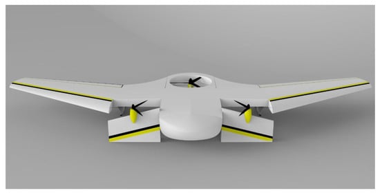
Figure 2.
VTOL mode.
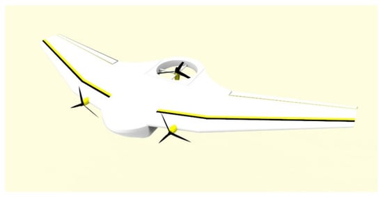
Figure 3.
Forward flight mode.
The design of the tilt-rotor power vertical takeoff and landing combines the advantages of both rotorcraft and fixed-wing designs, enabling the drone to take off and land without a runway, including on uneven surfaces. It features high speed and long endurance, greatly enhancing the drone’s operational versatility. Furthermore, vertical takeoff and landing mitigate the suboptimal performance during takeoff and landing resulting from the significant nose-down moment in flying-wing aerodynamics.
3. Aerodynamic Analysis
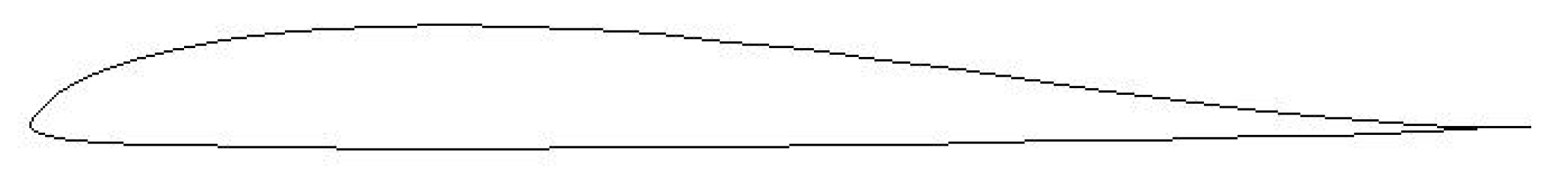
Based on the overall performance indicators and parameters, the lift coefficient is estimated at 0.25, prompting the selection of the S5020-84 airfoil in Figure 4.
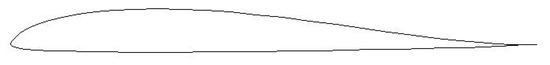
Figure 4.
S5020-84 airfoil.
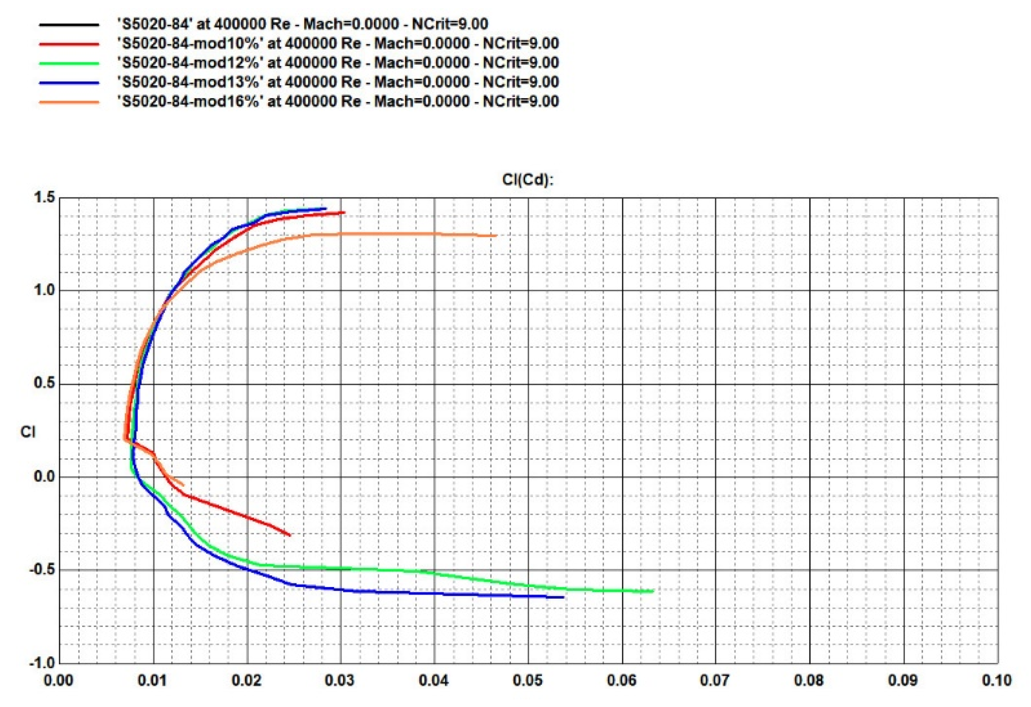
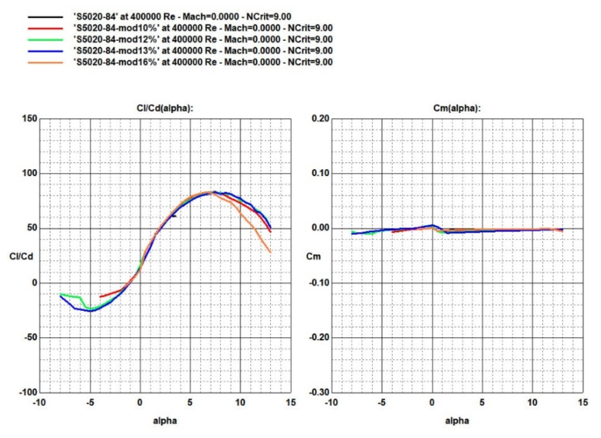
To further optimize the airfoil, the thickness of the original airfoil was adjusted, and performance comparisons were performed, as illustrated in Figure 5, Figure 6 and Figure 7.
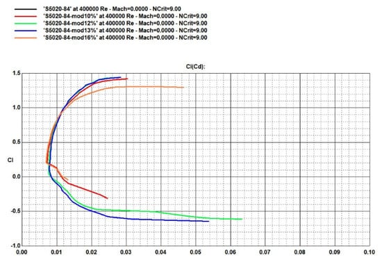
Figure 5.
Comparison of airfoil polar curves.
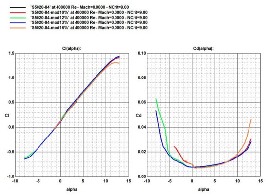
Figure 6.
Comparison of lift coefficient and drag coefficient of airfoil.
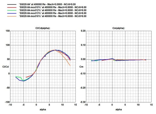
Figure 7.
Comparison of airfoil lift to drag ratio and torque coefficient.
For flying-wing configurations, the primary focus lies on the lift-to-drag ratio and the moment coefficient. It is evident that an increase in relative thickness results in a higher lift-to-drag ratio; however, the moment coefficient remains relatively stable between 10% and 13% relative thickness, with significant changes occurring only at 16%. Ultimately, the modified airfoil S5020-84-mod13% was selected for the drone, featuring a relative thickness of 13%. Based on this airfoil choice, the final wing parameters are detailed in Table 2.
Table 2.
Parameters of wing.
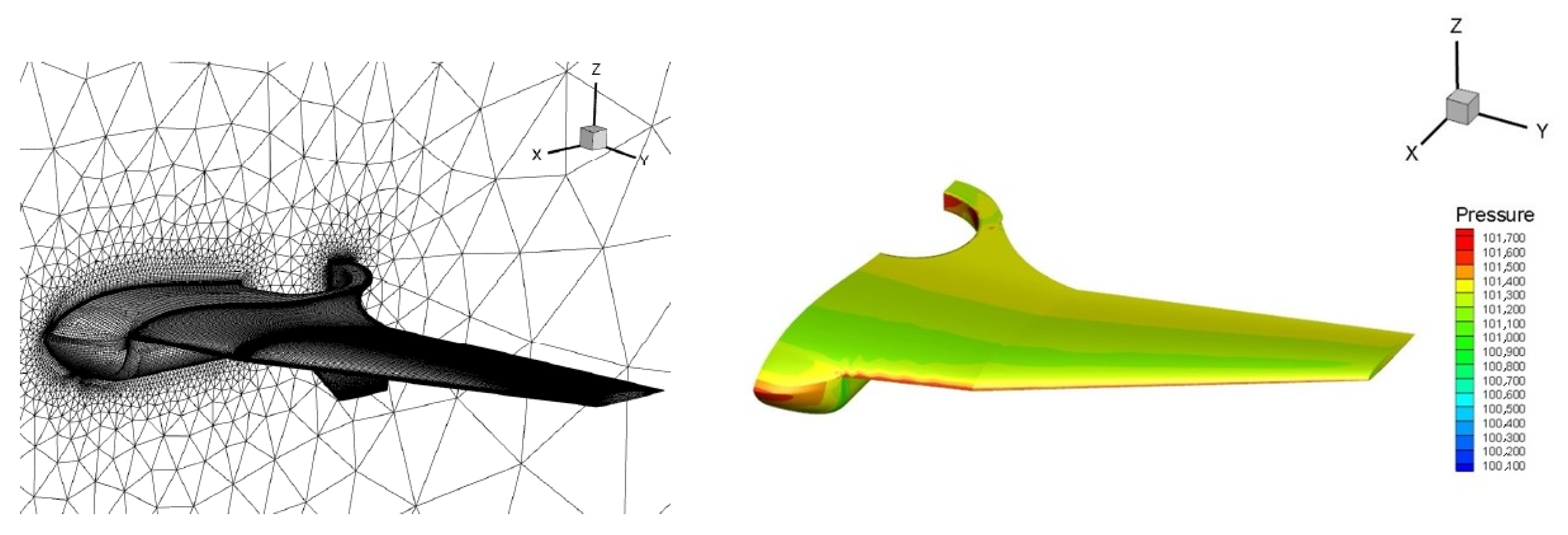
After determining the drone’s shape, the entire aircraft was subjected to grid generation and aerodynamic simulation analysis, as shown in Figure 8, which presents the grid generation and aerodynamic analysis results at an angle of attack of 0°.
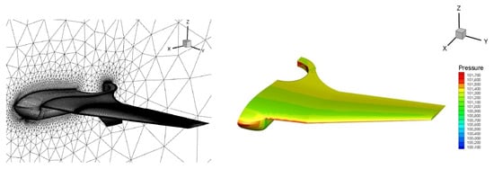
Figure 8.
CFD result showing pressure coefficient contours at 0° angle of attack.
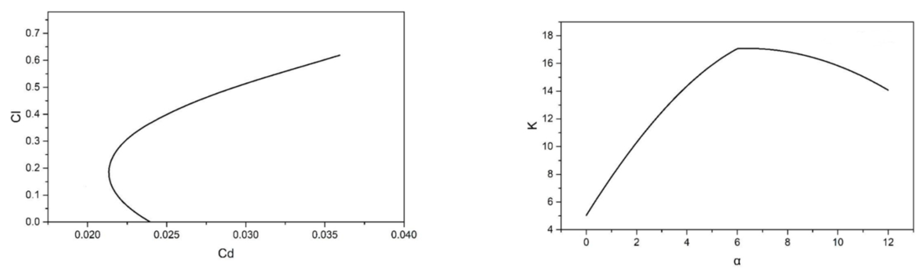
The relationship between the drag coefficient and the lift coefficient can be expressed as
where CD is the drag coefficient, CD0 is the drag coefficient unrelated to lift, A is a coefficient related to the airfoil, Reynolds number, and flight speed, and CL is the lift coefficient.
Based on this, the extreme curve of the drone can be obtained, from which the lift−to−drag ratio versus angle−of−attack curve can be plotted, as shown in Figure 9 and Figure 10. According to aerodynamic analysis data, the center of gravity position has a static stability margin of 5.57% for the entire aircraft, and the drone’s heading is stable.
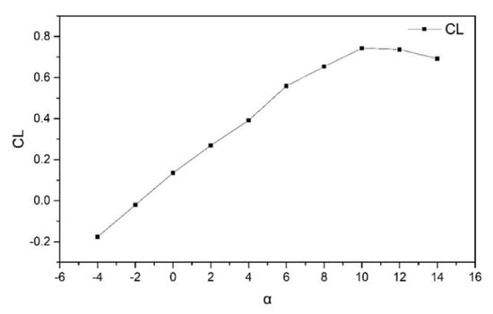
Figure 9.
Lift coefficient curve for varying angle of attack at forward flight mode.
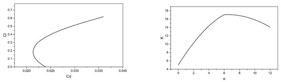
Figure 10.
Lift−drag curve and lift−to−drag ratio.
4. Structural Design
4.1. Aircraft Structure Design
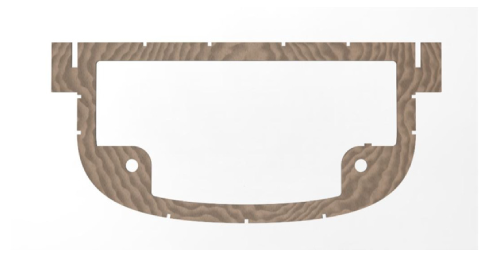
The fuselage houses the power supply, electronic speed controller, signal receiver, GPS, servos, and flight control system. The primary function of the fuselage frames is to support the payload, with a total of five frames arranged accordingly. The center is hollowed out to accommodate the payload, with step protrusions included to create a stable positioning area. Since all fuselage frames are oriented vertically along the fuselage axis and are connected to the wing root ribs without direct connections among themselves, and due to their relatively low stiffness, two carbon fiber tubes are designed beneath the payload platform to connect all fuselage frames, thereby enhancing the fuselage’s rigidity and axial strength. The rear fuselage frame requires an additional pivot point for mounting the rear motor. The shape of the fuselage frame is illustrated in Figure 11.
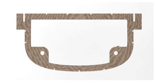
Figure 11.
Body frame.
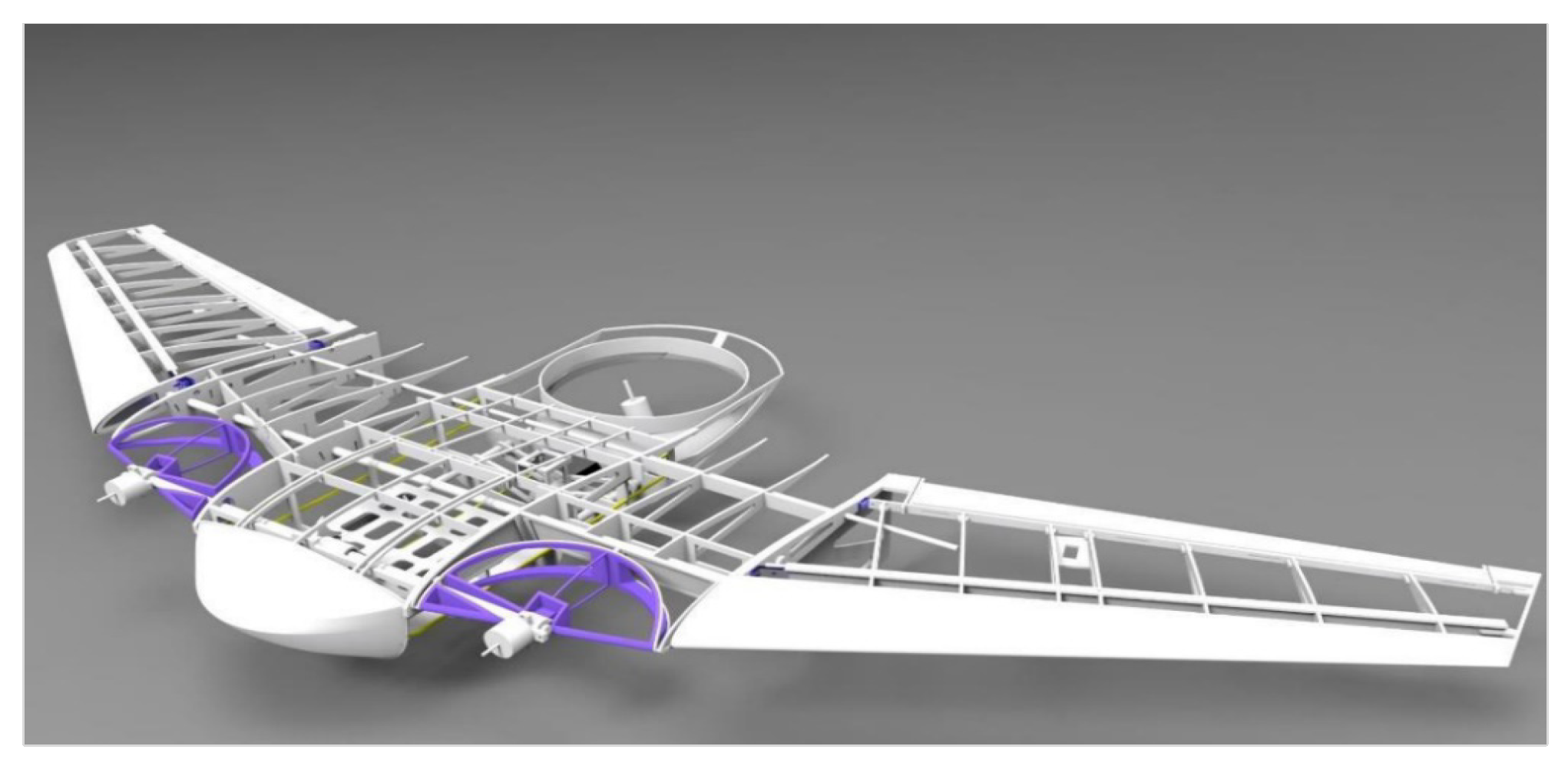
The structural design comprises the front wing beam, rear spar, wing ribs, and ailerons, as depicted in the three-dimensional structural design in Figure 12. Considering that this is a prototype, the manufacturing process needs to be both simple and efficient; therefore, some structural components employ additive manufacturing and laser cutting techniques.

Figure 12.
Result of structural design.
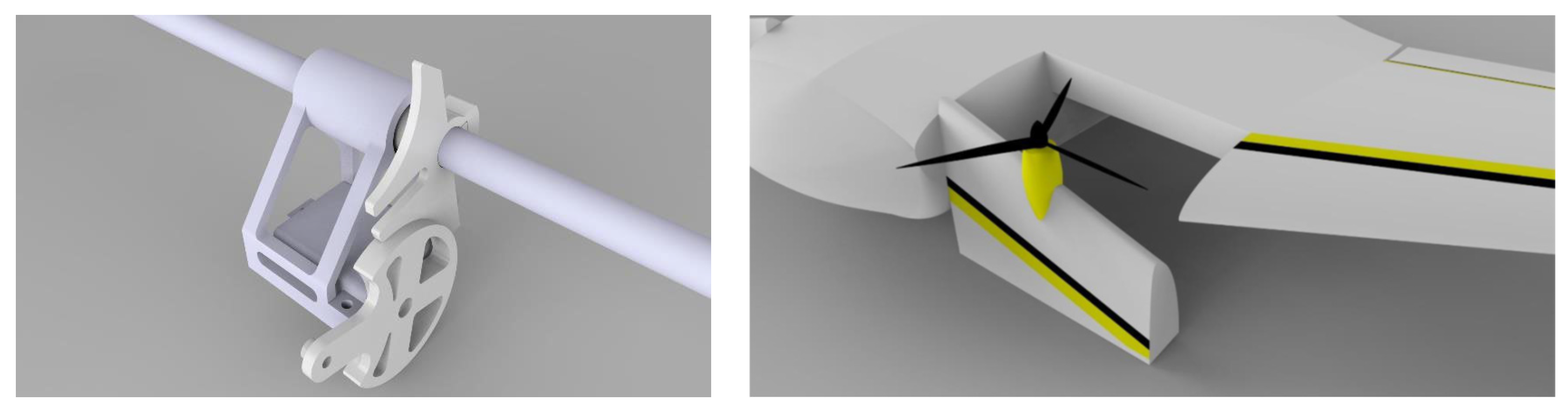
4.2. Design of Tilting Mechanism
In accordance with the overall design of the aircraft, the tilting mechanism utilizes a single-pin, four-slot uniformly distributed Geneva drive mechanism to enable the transition between vertical takeoff and landing and forward flight. The working principle is as follows: the Geneva mechanism operates in two configurations—external and internal meshing. In the external meshing configuration, the Geneva wheel and the pivot arm rotate in opposite directions, whereas in the internal meshing configuration, they rotate in the same direction. The single-arm external meshing Geneva mechanism is composed of a pivot arm equipped with a cylindrical pin, a Geneva wheel with four radial slots, and a supporting frame. As the cylindrical pin on the continuously rotating pivot arm enters one of the radial slots, it drives the Geneva wheel to rotate by 90 degrees; once the cylindrical pin exits the slot, the Geneva wheel halts its rotation. With one full revolution of the pivot arm, the Geneva wheel completes one intermittent rotation cycle. The final structure of the UAV tilting mechanism is depicted in Figure 13.

Figure 13.
The tilting mechanism design.
5. Control System Design
The research on flight control for the vertical takeoff and landing, as well as fixed-wing cruise phases of UAVs, is already well-established and will not be discussed further in this paper. The focus here is on the control implementation during the transition phase.
In transition mode, the aircraft possesses both fixed-wing and helicopter control characteristics. As the tilt angle and flight speed vary, the aircraft’s aerodynamic properties change significantly, introducing strong coupling and nonlinearity into the control system. This gives rise to issues such as actuator redundancy and control allocation. During the tilt transition process, the aircraft’s control modes are as follows:
- (1)
- Roll control: differential thrust (left–right motors) + ailerons;
- (2)
- Pitch control: differential thrust (front–rear motors) + elevators;
- (3)
- Yaw control: tail motor tilt;
- (4)
- Altitude control: rotor thrust + pitch adjustment;
- (5)
- Airspeed control: rotor thrust + rotor tilt angle.
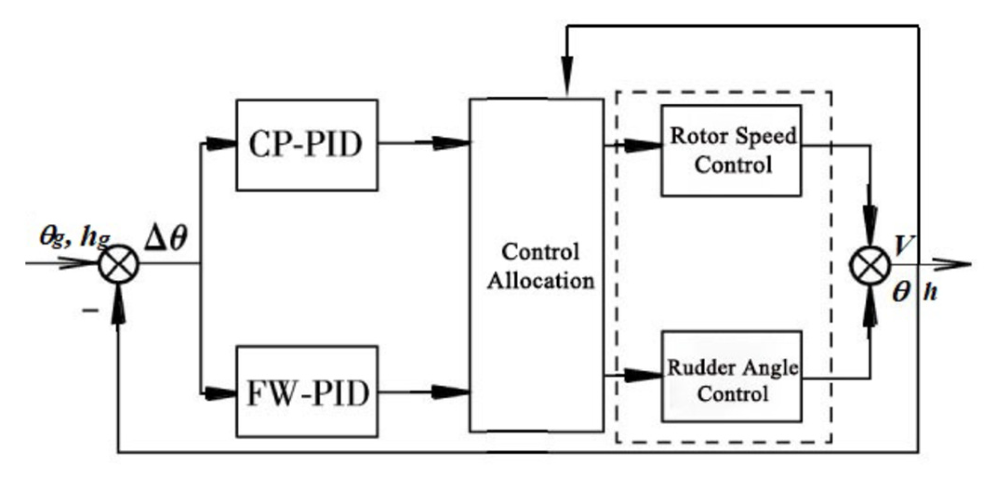
As observed from the control modes during the tilt transition process, the helicopter control mode and fixed-wing control mode are fully coupled, resulting in the issue of actuator redundancy. Therefore, effective decoupling must be achieved through an appropriate control allocation strategy, as illustrated in Figure 14. The tilt transition process can be broken down into helicopter mode and fixed-wing mode, and the overall control process is realized by linearly superimposing these modes, weighted by corresponding functions. During the entire tilt transition, the aircraft’s speed has a considerable impact on lift, and there is significant coupling between aerodynamic forces and rotor thrust. As a result, the speed range is used as the selection criterion for the weighting functions. The expression for the weighting function is as follows:
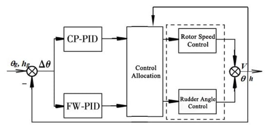
Figure 14.
Controller for transition mode.
In the equation, V denotes the flight speed of the UAV, while and represent the components of the weighting function.
The design of the transition strategy must adhere to the principles of both speed and smoothness. Referring to the tilt mechanism used in dual-rotor systems, the process begins by slowly tilting the nose rotors to a certain angle and holding them in position, allowing the aircraft to gain sufficient initial speed. Then, the rotors are gradually tilted to 90 degrees, completing the tilt transition. During this process, it is crucial to maintain a balance between rotor thrust, aircraft lift, and gravity, ensuring that the aircraft’s altitude remains stable without large fluctuations.
Once the flight control system is established, the Mission Planner software v1.3.74.2 is used to flash the flight control program. The tuned PID parameters are loaded into the relevant control modules, and after further real-world adjustments, the entire flight control tuning process can be finalized.
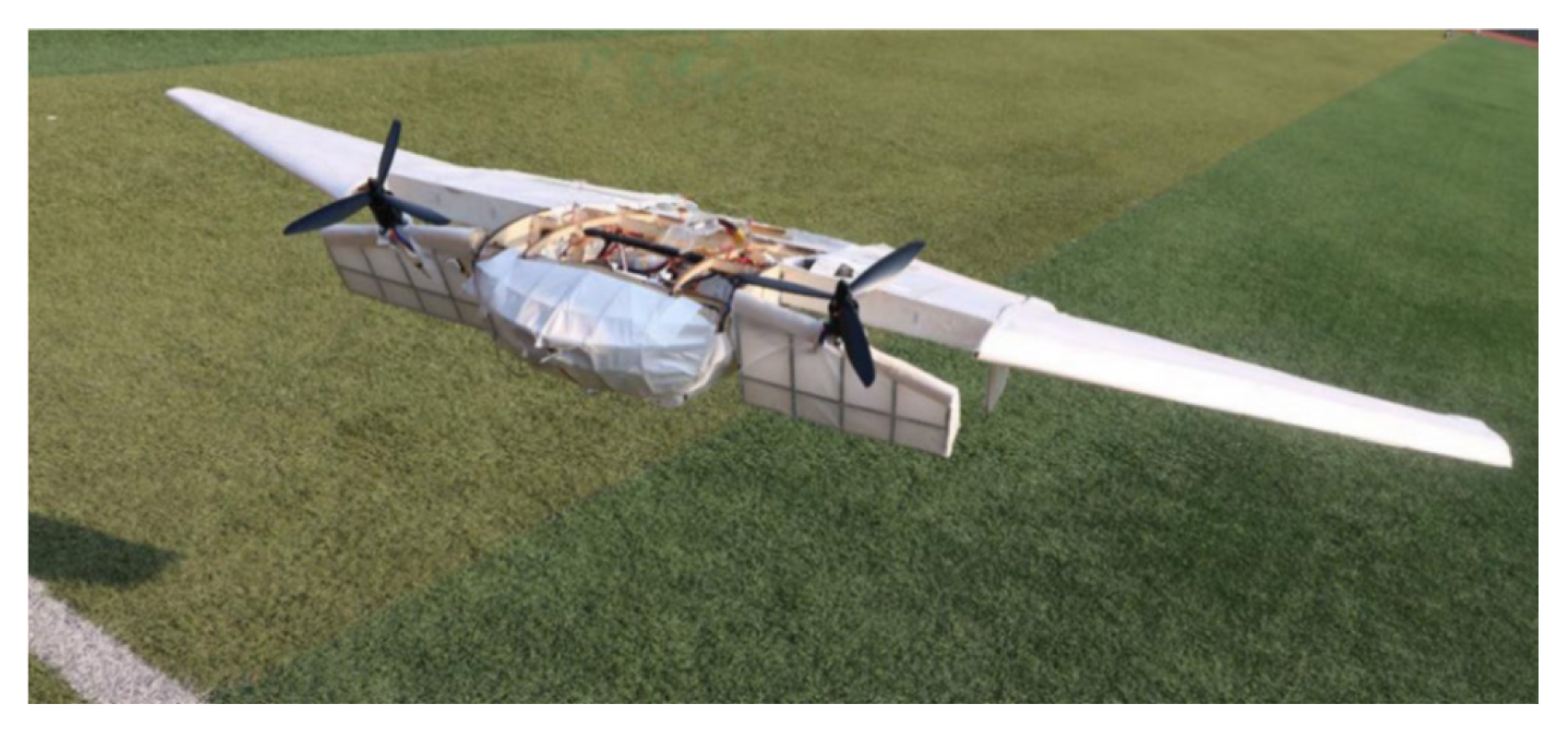
6. Flight Tests
First, flight tests were conducted in vertical takeoff and landing (VTOL) mode, and the controller parameters were fine-tuned until stable flight was achieved. Next, the forward flight mode controller parameters were adjusted through forward flight testing. Finally, the transition mode controller parameters were tested in three phases: with the forward rotors tilted at 45° and the airspeed around 5 m/s, the CP-PID parameters were calibrated via forward flight; with the forward rotors tilted at 45° and the airspeed around 15 m/s, the FW-PID parameters were established through forward flight testing; and during flight tests where the airspeed varied between 5 m/s and 15 m/s, a hybrid controller combining both VTOL and forward flight control modes were employed. The results of the flight tests are shown in Figure 15, Figure 16 and Figure 17.

Figure 15.
VTOL mode.
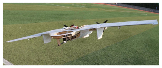
Figure 16.
Forward flight mode.

Figure 17.
Transition mode.
7. Discussion and Conclusions
This paper presents the design, analysis, and flight testing of a newly configured tilt-rotor tri-copter UAV. The flight test results confirm that the UAV fulfills its design requirements for vertical takeoff, landing, and forward flight, and successfully demonstrate the feasibility of the transition from vertical takeoff and landing mode to forward flight mode.
Author Contributions
Conceptualization, Z.S.; methodology, Z.S.; software, Z.S.; validation, Z.S. and F.L.; formal analysis, Z.S.; investigation, Z.S. and F.L.; resources, Z.S.; data curation, Z.S.; writing—original draft preparation, Z.S.; writing—review and editing, Z.S.; project administration, Z.S. All authors have read and agreed to the published version of the manuscript.
Funding
This research received no external funding.
Institutional Review Board Statement
Not applicable.
Informed Consent Statement
Not applicable.
Data Availability Statement
If anyone is interested in our research, please contact us via email.
Acknowledgments
This project is supported by AEROFUGIA at Sichuan. The authors would like to thank all researchers of AEROFUGIA, and Pix4 UAV for providing a great open-source platform to build upon.
Conflicts of Interest
The authors declare no conflicts of interest.
References
- Anderson, S.B. History Overview of VSTOL Aircraft Technology. NASA-TM81280. 1981. Available online: https://ntrs.nasa.gov/api/citations/19810010574/downloads/19810010574.pdf (accessed on 10 January 2017).
- O’Rourke, R. V-22 Osprey Tilt-Rotor Aircraft: Background and Issues for Congress; Congressional Research Service Reports; Library of Congress. Congressional Research Service: Washington, DC, USA, 2010. [Google Scholar]
- Bolkcom, C. V-22 Osprey Tilt-Rotor Aircraft. CRS Report for Congress. 2002. Available online: https://www.everycrsreport.com/reports/IB86103.html (accessed on 10 January 2017).
- Anthony, J.; Calise, A.I.; Rysdyk, R.T. Adaptive Model Inversion Flight Control for Tiltrotor Aircraft. In Proceedings of the AlAA Guidance Navigation and Control Conference; AIAA-97-3758. pp. 1633–1639. Available online: https://citeseerx.ist.psu.edu/document?repid=rep1&type=pdf&doi=69ffab22e61f56282e6a7423c11cffef5e41031e (accessed on 10 January 2017).
- Chang, H.Y. Overall Design and Control System Design of a TriTri-Tilt Rotor Unmanned Aerial Vehicle. Master’s Thesis, Nanjing University of Aeronautics and Astronautics, Nanjing, China, 2018. [Google Scholar]
- Settle, B.; Wise, T. Bell Eagle Eye TR-911X–Tiltrotor Unmanned Aerial Vehicle: Recent Developments, Auto-land Integration, and Flight Test Demonstrations. Annu. Forum Proc. Am. Helicopter Soc. 2000, 56, 306–319. Available online: https://www.researchgate.net/publication/291531050_Bell_makes_first_flight_with_new_eagle_eye_demonstrator (accessed on 10 January 2017).
- Kang, Y.-S.; Park, B.-J.; Cho, A.; Yoo, C.-S.; Choi, S.-W. Envelop expansion flight test of flight control systems for TR-60 tilt-rotor UAV. In Proceedings of the 2013 13th International Conference on Control, Automation and Systems, Gwangju, Republic of Korea, 20–23 October 2013; pp. 1866–1871. [Google Scholar]
- Zhang, L.; Sun, K.J.; Ye, C.; Cui, L.B. Flight Mechanics Modeling of the New Configuration Tilt-rotor. Adv. Aeronaut. Sci. Eng. 2019, 10, 462–470. [Google Scholar]
- Shao, Y.J.; Liu, L.; Cao, X.; He, Y.T. Research status and key technologies of tilt-rotor UAVs. Tactical Missile Technol. 2022, 2022, 12–20. Available online: https://qikan.cqvip.com/Qikan/Article/Detail?id=7107134483 (accessed on 10 January 2017).
- Chen, K. STOVL Unmanned Aerial Vehicle Flight Dynamic Analysis, Control Law Design and Test. Ph.D. thesis, Nanjing University of Aeronautics and Astronautics, Nanjing, China, 2016. [Google Scholar]
- Chen, H. Numerical Study on Unsteady Aerodynamic Force of a Tiltrotor Aircraft in Conversion Mode. Ph.D. Thesis, Nanjing University of Aeronautics and Astronautics, Nanjing, China, 2018. [Google Scholar]
- Wang, Z.; Gong, Z.; Chen, Y.; Sun, M.; Xu, J. Practical control implementation of tri-tiltRotor flying wing unmanned aerial vehicles based upon active disturbance rejection control. Proc. Inst. Mech. Eng. Part G J. Aerosp. Eng. 2020, 234, 943–960. [Google Scholar] [CrossRef]


Disclaimer/Publisher’s Note: The statements, opinions and data contained in all publications are solely those of the individual author(s) and contributor(s) and not of MDPI and/or the editor(s). MDPI and/or the editor(s) disclaim responsibility for any injury to people or property resulting from any ideas, methods, instructions or products referred to in the content. |
© 2025 by the authors. Licensee MDPI, Basel, Switzerland. This article is an open access article distributed under the terms and conditions of the Creative Commons Attribution (CC BY) license (https://creativecommons.org/licenses/by/4.0/).