Proceeding Paper

Configuration Design and Analysis of Tilt-Rotor-Type Flying Car †

School of Transportation Science and Engineering, Beihang University, Beijing 102206, China
*
Author to whom correspondence should be addressed.
Presented at the 2nd International Conference on Green Aviation (ICGA 2024), Chengdu, China, 6–8 November 2024.
Eng. Proc. 2024, 80(1), 33; https://doi.org/10.3390/engproc2024080033
Published: 25 February 2025
(This article belongs to the Proceedings of 2nd International Conference on Green Aviation (ICGA 2024))

Abstract

Flying cars are envisioned as key components of the Future Comprehensive Transport Network System. Current flying car designs struggle to balance ground maneuverability with aerial agility, which means they cannot operate on standard roads (3.5 m width). Additionally, the low energy density of existing aviation batteries limits their operational range. Therefore, a high lift-to-drag ratio (L/D) improves efficiency by reducing drag and extending the operational range. This leads to more economical and efficient flight performance, making it particularly beneficial for flying cars. This paper addresses the challenges of the land–air amphibious design and high-L/D configuration design of flying cars, and Computational Fluid Dynamics (CFD) simulations were conducted to optimize the overall configuration of a flying car, followed by creating a 1:4-scale model and validating its aerial posture. The results confirmed the structural integrity of the tilting and folding wing design for amphibious flying cars, achieving a fixed-wing mode L/D of 11. This design effectively addresses the traditional flying car issue of neglecting ground travel requirements by focusing solely on the flight capabilities of simulated aircraft or drones.

1. Introduction

Flying cars are a transportation tool designed for future urban three-dimensional transportation [1,2,3,4] and are intended to facilitate efficient and rapid switching between two modes of travel—air flight and ground driving [5,6,7]—as well as facilitating vertical takeoff and landing, which would significantly reduce greenhouse gas emissions [8]. The current design of the flying car does not meet the necessary amphibious operation standards for both land and air. With the existing design, the flying car is unable to operate on the ground for extended periods. The fixed-wing flying car, exemplified by the Aeromobile, is contingent upon the availability of an airport runway for takeoff and landing and thus has limited operational flexibility; modular flying cars, such as GAC Group and Xpeng products, enable both land and air operation but suffer from having limited range due to suboptimal aerodynamic efficiency and the low energy density of their power systems.
This paper presents an overall configuration design for flying cars, addressing the challenges of land–air amphibious compatibility and achieving an aerodynamic shape with a high lift-to-drag ratio.

2. Overall Design

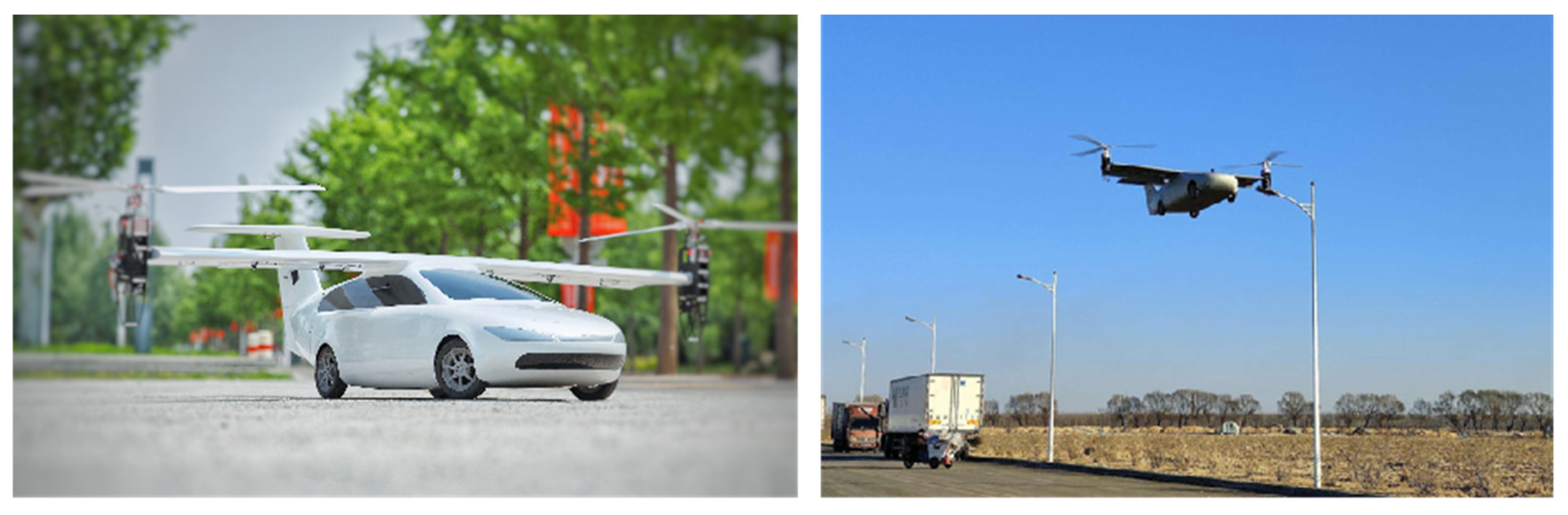
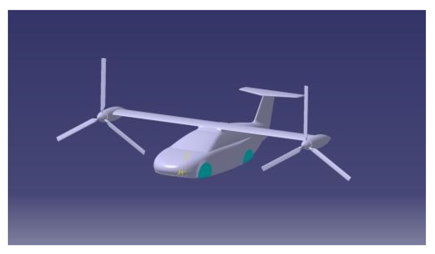
2.1. Overall Configuration Design

In designing the overall configuration of flying cars, consideration is given to simultaneously accommodating vertical takeoff and landing (VTOL) capabilities and long-distance endurance [9,10]. The flight module design described in this paper adopts a tilt-rotor configuration. This design allows the flying car to utilize rotors for lift during vertical takeoff and landing while transitioning to a fixed-wing flight mode during cruising, thereby enhancing flight efficiency and speed. Furthermore, this design provides excellent transition capabilities between vertical takeoff and horizontal flight.
Additionally, to ensure ground maneuverability, the flight module is required to incorporate a folding mechanism. As the flying car switches to ground operation mode, the wings can fold to reduce the overall vehicle width. This design considers both the aerodynamic characteristics of the flying car and the practicality and convenience of ground travel.
Therefore, the flight module of the flying car is designed with a tilt-rotor configuration that includes folding capabilities. The theoretical cruising speed of the fixed-wing model is 300 km/h, with a total weight of 1000 kg, classifying it as a low-speed aircraft. Based on wingspan constraints, a supercritical airfoil is selected. The tail is configured with a fixed-tail support layout, and the propulsion system is integrated into a short-tilt nacelle at the wingtip [Figure 1].
With the wings folded, the total width of the vehicle is 1.89 m, allowing it to operate normally on standard roads (3.5 m wide). The short-tilt nacelle, positioned at the wingtip, features a tilt actuator that enables rotation from 0° to 180°, fulfilling the movement requirements for both fixed-wing operation and folded conditions. The cockpit is designed for two occupants, with a maximum effective payload of 180 kg. The chassis is designed for four-wheel independent driving. The following table [Table 1] presents the key parameters of the full-scale prototype of the flying car:

2.2. Systematic Literature Review

A 1:4-scale model of the flying car was developed using CATIA to validate the feasibility of the configuration design. The fuselage length is 1.9 m, and the wingspan is 2.25 m [Figure 2]. The fixed-wing airfoil is based on the NACA-E395 airfoil design, which is a low-speed airfoil with a high L/D ratio, capable of meeting flight performance requirements across various flight modes for the tilt-rotor flying car.

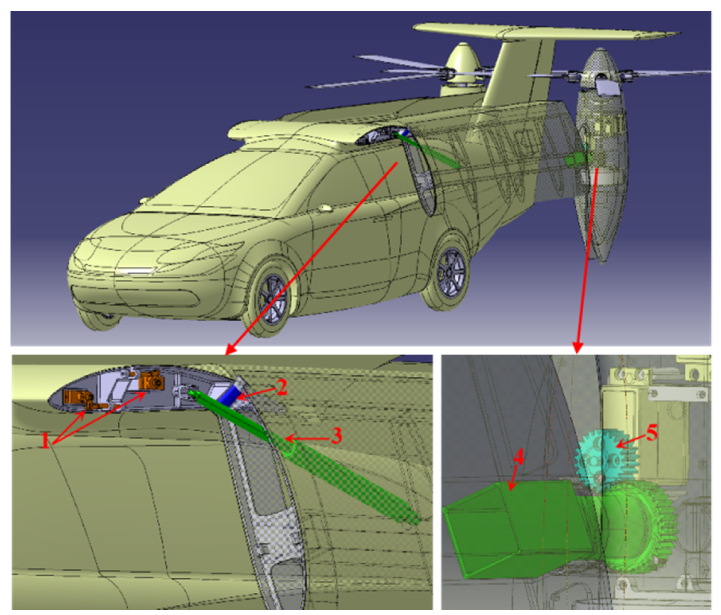
2.2.1. Folding Wing Mechanism

The folding wing mechanism is driven by a linear motor, with the front connected to the top of the fuselage via a universal joint and the rear connected to the midsection of the fixed wing via a hinge. The reciprocating motion of the linear motor drives the fixed wing to rotate along a 45° inclined axis at the wing root, executing wing folding/unfolding actions.

2.2.2. Swiveling Actuator Mechanism

The tilt-rotor flying car employs a swiveling actuator to transition the tilt cabin from a vertical rotor mode to a fixed-wing mode, facilitated by a gear-driven rotation of the tilt cabin.

3. Simulation Parameter Settings and Result Analysis

3.1. Flow Field Simulation Settings in Fixed-Wing Flight Mode

To realistically simulate the flight dynamics of a flying car, the outlet surface of the fluid computational domain is defined as a pressure outlet, while all other far-field boundaries are set as velocity inlets [Figure 3]. The body surface is specified as a no-slip wall. The wing chord length, c, is 350 mm, with the far-field boundary located at a distance of 30c (0.35 m). The boundary conditions are illustrated in the accompanying figure. The angle of attack, α, is set to 0°, and the incoming flow velocity varies from 10 m/s to 100 m/s, corresponding to a Reynolds number (Re) range of 200,000 to 2,000,000. The outlet pressure is maintained at 101,325 Pa, and the time step is 0.001 s.
The unsteady viscous flow field is solved using the Reynolds-averaged Navier–Stokes (RANS) equations, employing the SST k-ω turbulence model and an implicit unsteady method for flow field computation. Considering the rotation of the rotors during forward flight, a moving mesh approach is utilized. A prism layer mesh with 10 layers is implemented, with the first-layer thickness set to 0.01c for the body and 0.001c for the rotor, resulting in a total mesh count of 2.8 million. Grid convergence studies across different mesh densities demonstrate consistent lift and drag results, thus confirming that the selected parameters meet the simulation requirements.

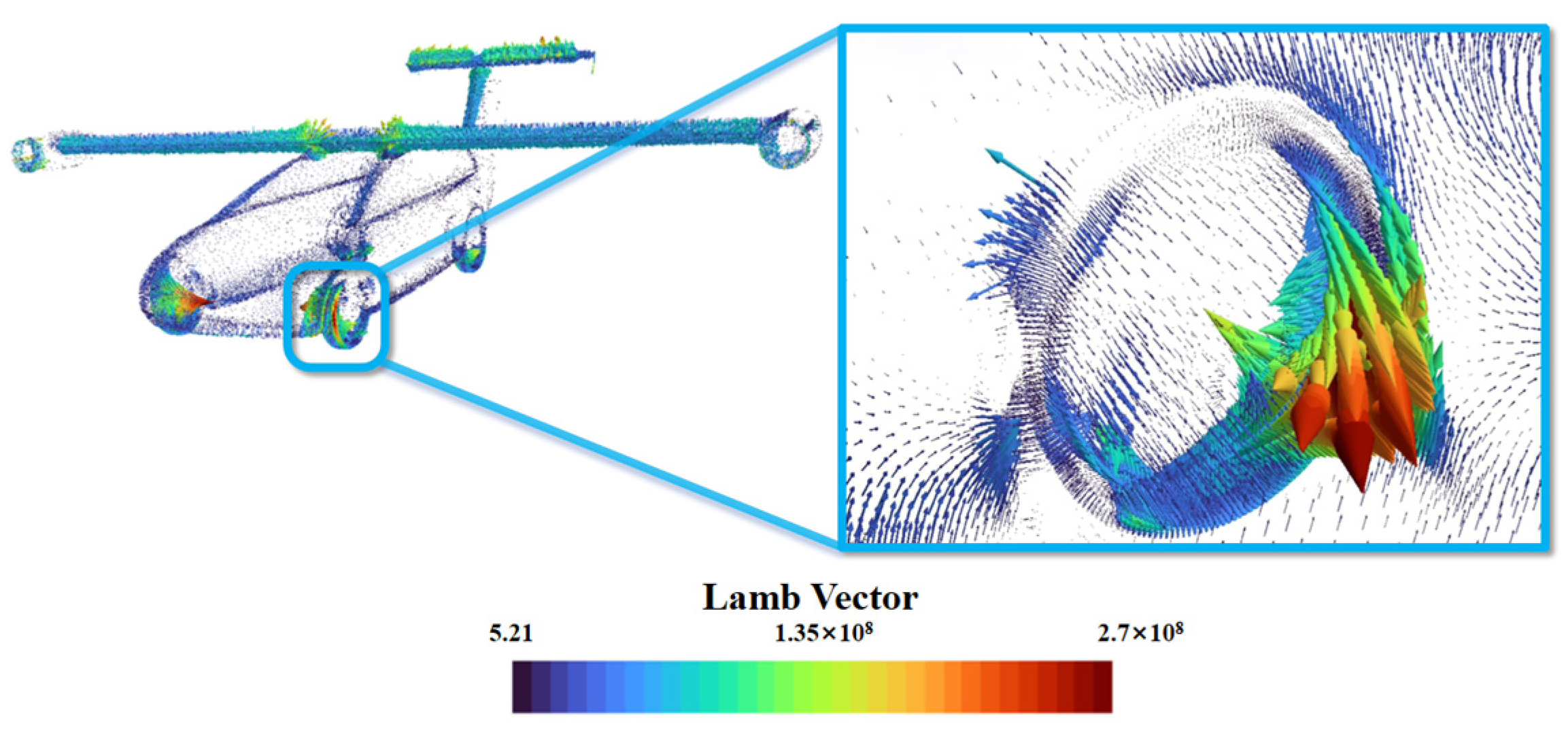
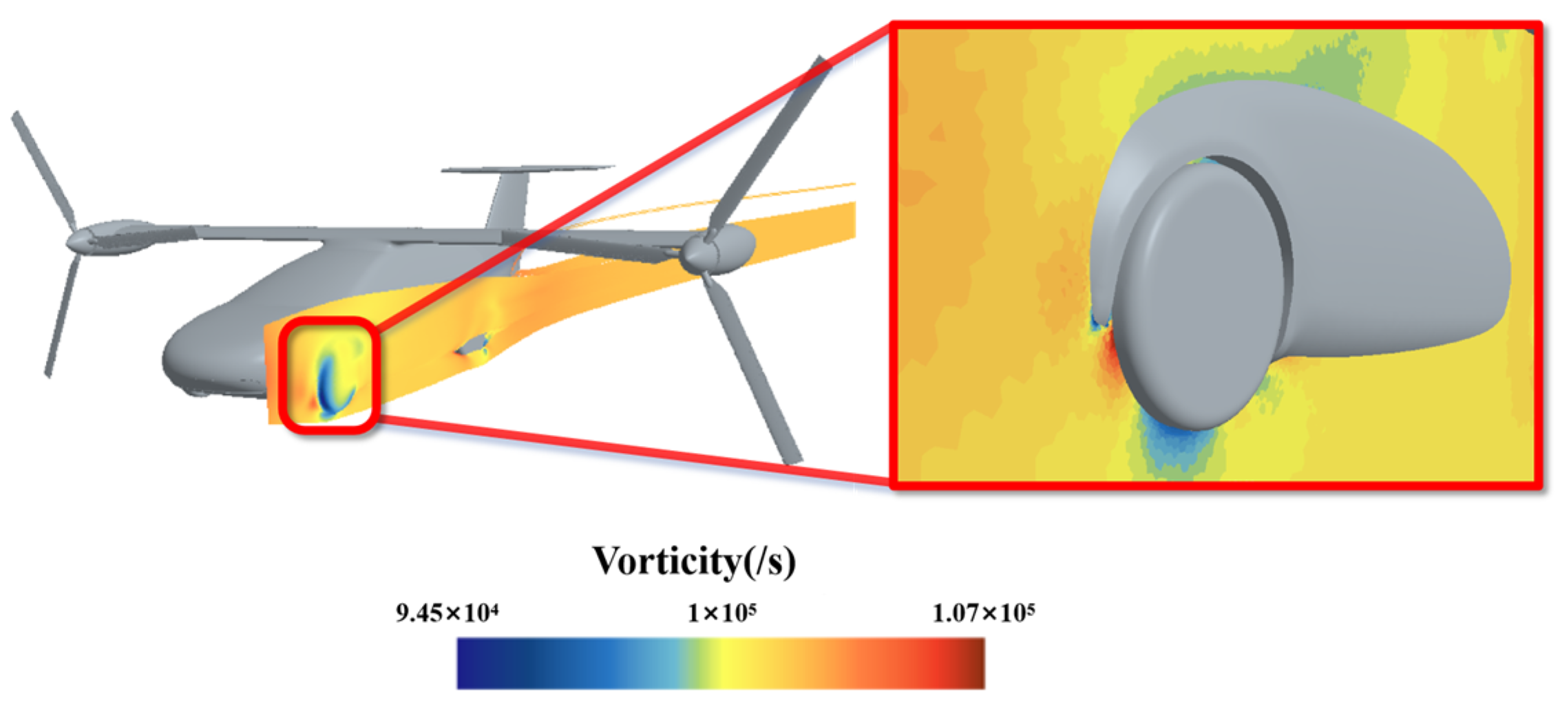
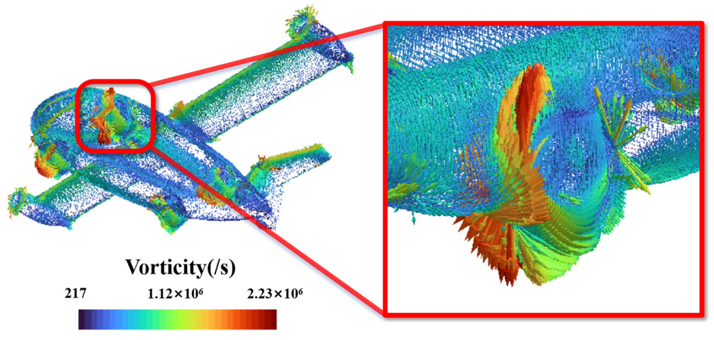
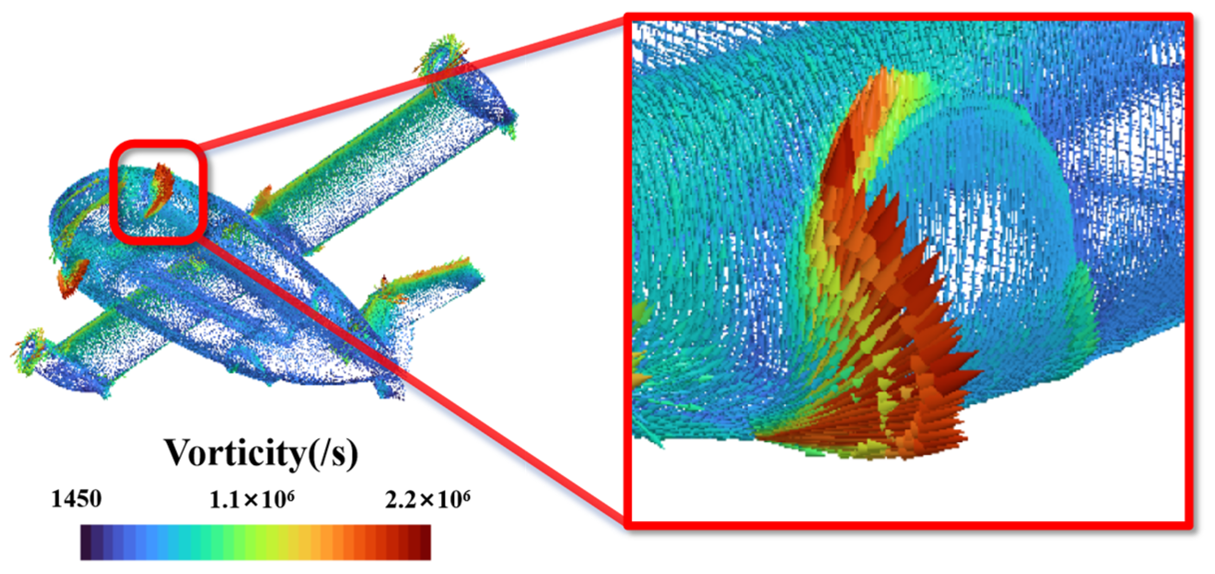
3.2. Flow Field Simulation Result Analysis

The simulation results of the L/D ratio for the 1:4-scale model of the flying car at different flow velocities are presented in Table 2. The Flying car surface pressure distribution is showed in Figure 4.
The theoretical cruise speed of the full-size flying car is 300 km/h (approximately 83.33 m/s). Therefore, the aerodynamic simulation testing range is set between incoming flow velocities of 10 m/s to 100 m/s to simulate actual flight conditions. During the simulation process, the incoming flow velocity is varied, with specific speeds incrementally set from 10 m/s to 100 m/s.
The L/D ratio of the 1:4 model within a range of incoming flow velocities from 25 m/s to 100 m/s is between 6.89 and 7.24. Compared to a helicopter, which has an L/D ratio of 4–5, the flying car exhibits superior aerodynamic efficiency within this velocity range. However, it still shows a significant difference compared to general aviation aircraft, which have an L/D ratio of 10–15.
The vortex distribution [Figure 5 and Figure 6] reveals the formation of distinct vortices around the wheels. This is further supported by the pressure distribution map of the tire cross-section, which shows a significant high-pressure zone at the windward position of the front wheel, indicating that it is a major contributor to the overall drag of the flying car.

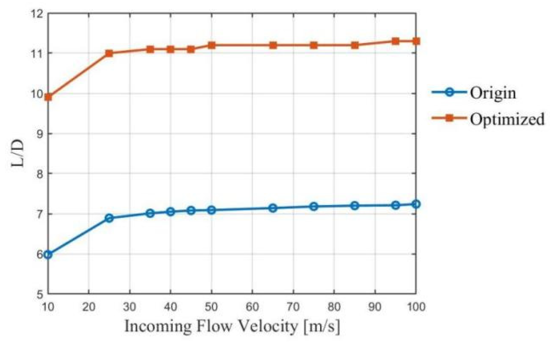
4. Design Optimization and Simulation Verification

To enhance the endurance of the tilt-rotor flying car, it is necessary to optimize its external design. As mentioned in Section 2, the simulation results indicate that significant vortices form at the tire when the flying car is in fixed-wing mode. In the optimization design, it is considered that the tires should retract into the fuselage, ensuring that no tires or other hanging components are exposed during flight mode [Figure 7].
The simulation involves folding the tires of the flying car into the fuselage and optimizing the fuselage data in CATIA to achieve a clean configuration without exposed tires in fixed-wing cruise mode [Figure 8 and Figure 9]. The simulation verification [Table 3] shows that the optimized configuration significantly reduces overall drag when the flying car is in fixed-wing cruise mode.

5. Discussion and Conclusions

In this paper, an overall configuration design of a flying car that can meet the requirements for amphibious operation on land and in the air and can realize vertical takeoff and landing on the ground is designed, and the lift-to-drag ratio of the configuration is verified through optimization, which is summarized as follows:
(1)
The clean configuration design can effectively improve the L/D ratio of the flying car [Table 3, Figure 10].
(2)
It is necessary to promote the design of the tilt-rotor blade [11] and the matching of the rotor drive motor’s power parameters for the flying car in future work.

Author Contributions

Conceptualization, C.C.; methodology, A.L. software, Z.T.; validation, Z.T. and C.C.; formal analysis, A.L.; investigation, M.X. and Y.W.; resources, F.C. and S.Y.; data curation, Z.T.; writing—original draft preparation, A.L.; writing—review and editing, M.X.; funding acquisition, S.Y. and F.C. All authors have read and agreed to the published version of the manuscript.

Funding

This work is supported by the Fundamental Research Funds for the Central Universities(501QYJC2024146014).

Data Availability Statement

The author declares the use of AI and AI-assisted technologies in the writing process of this article. The tool used was GPT-3.5. This tool was used in the following fashion: enhancement of sentences for readability and language in Section 4. After using the tool, the author declares that he reviewed and edited the content as needed and take(s) full responsibility for the content of the publication.

Acknowledgments

The authors would like to thank Professor Zhou Chao of the School of Transportation Science and Engineering BUAA for his helpful discussion on topics related to this work.

Conflicts of Interest

The authors declare no conflicts of interest.

References

  1. Zhang, X.; Xu, W.; Shi, Y.; Cai, M.; Li, F. Study on the Effect of Tilting-Rotor Structure on the Lift of Small Tilt Rotor Aircraft (WOS:000426453700068). In Proceedings of the 2017 2nd International Conference on Advanced Robotics and Mechatronics (ICARM), Hefei and Tai’an, China, 27–31 August 2017; pp. 380–385. [Google Scholar] [CrossRef]
  2. Yu, Z.; Zhang, J.; Wang, X. Study of Modeling and Optimal Take-Off Scheme for a Novel Tilt-Rotor UAV. Sensors 2022, 22, 9736. [Google Scholar] [CrossRef] [PubMed]
  3. Kosmatka, J.; Lake, R. Passive Approach of Controlling Twist in Composite Tilt-Rotor Blades; Chopra, I., Ed.; WOS: A1996BF67T00009; SPIE: Bellingham, WA, USA, 1996; Volume 2717, pp. 146–157. [Google Scholar] [CrossRef]
  4. Sasongko, R.; Muhammad, B. Modeling and Simulation of Rotor Dynamics of a Tilt-rotor Aircraft (WOS:000516718200015). In Proceedings of the 2017 5th International Conference on Instrumentation, Communications, Information Technology, and Biomedical Engineering (ICICI-BME), Bandung, Indonesia, 6–7 November 2017; pp. 51–56. [Google Scholar] [CrossRef]
  5. Pardede, W.M.; Adhitya, M. Take off and landing performance analysis for a flying car model using wind tunnel test method. AIP Conf. Proc. 2020, 2227, 020030. [Google Scholar] [CrossRef]
  6. Ai, T.; Xu, B.; Xiang, C.; Fan, W.; Zhang, Y. Modeling and Multimode Analysis of Electrically Driven Flying Car (WOS:000612041300200). In Proceedings of the 2020 International Conference on Unmanned Aircraft Systems (ICUAS), Athens, Greece, 1–4 September 2020; pp. 1565–1571. [Google Scholar] [CrossRef]
  7. Shamiyeh, M.; Bijewitz, J.; Hornung, M. A review of recent personal air vehicle concepts. In Proceedings of the Aerospace Europe 6th CEAS Conference, Bucharest, Romania, 16–20 October 2017; Volume 913, pp. 1–18. [Google Scholar] [CrossRef]
  8. Zhang, T.; Barakos, G.N.; Furqan; Foster, M. High-fidelity aerodynamic and acoustic design and analysis of a heavy-lift eVTOL. Aerosp. Sci. Technol. 2023, 137, 108307. [Google Scholar] [CrossRef]
  9. Kim, K.; Hwang, K.; Kim, H. Study of an adaptive fuzzy algorithm to control a rectangular-shaped unmanned surveillance flying car. J. Mech. Sci. Technol. 2013, 27, 2477–2486. [Google Scholar] [CrossRef]
  10. Zhang, J.; Liu, Y.; Zheng, Y. Overall eVTOL aircraft design for urban air mobility. Green Energy Intell. Transp. 2024, 3, 100150. [Google Scholar] [CrossRef]
  11. Abà, A.; Barra, F.; Capone, P.; Guglieri, G. Mathematical Modelling of Gimballed Tilt-Rotors for Real-Time Flight Simulation. Aerospace 2020, 7, 124. [Google Scholar] [CrossRef]
Figure 1. Flying car: 1:4-scale model.
Engproc 80 00033 g001
Figure 2. Flying car: 1:4-scale model (1: folding wing locking mechanism; 2: folding wing rotational axis; 3: folding wing actuation mechanism; 4: swiveling actuator-driven gear; 5: swiveling actuator drive gear).
Engproc 80 00033 g002
Figure 3. CFD simulation settings.
Engproc 80 00033 g003
Figure 4. Flying car surface pressure distribution.
Engproc 80 00033 g004
Figure 5. Flying car surface vortex distribution.
Engproc 80 00033 g005
Figure 6. Flying car front-left-wheel pressure distribution.
Engproc 80 00033 g006
Figure 7. Flying car clean configuration design.
Engproc 80 00033 g007
Figure 8. Flying car surface vortex distribution.
Engproc 80 00033 g008
Figure 9. Flying car (clean configuration design) surface vortex distribution.
Engproc 80 00033 g009
Figure 10. Variation Curve of L/D.
Engproc 80 00033 g010
Table 1. Key parameters of the full-scale prototype of the flying car.
Wingspan8.98 m
Width (folded)1.89 m
Maximum flight speed300 km/h
Maximum ground speed150 km/h
Flight endurance time1 h
Payload180 kg
Table 2. Flow field simulation data.
Incoming Flow Velocity (m/s)Lift (N)Drag (N)L/D
1026.94.55.98
25180.626.26.89
35356.950.97.01
40467.766.37.05
45592.483.77.08
50732.9103.37.09
651242.7174.17.14
751657230.97.18
852132.62967.20
952667.9370.27.21
1002958408.87.24
Table 3. Flow field simulation data (optimized).
Incoming Flow Velocity (m/s)Lift(N)Drag(N)L/D
1027.52.89.9
25183.016.711.0
35361.532.511.1
40472.542.411.1
45598.553.711.1
50739.766.211.2
651252.5112.011.2
751669.5149.011.2
852146.4191.011.2
952685.4238.711.3
1002977.0264.311.3
Disclaimer/Publisher’s Note: The statements, opinions and data contained in all publications are solely those of the individual author(s) and contributor(s) and not of MDPI and/or the editor(s). MDPI and/or the editor(s) disclaim responsibility for any injury to people or property resulting from any ideas, methods, instructions or products referred to in the content.

