Abstract
As a core technology in the future of aviation transportation, the safety and reliability of electric vertical take-off and landing (eVTOL) aircraft are of paramount importance. Electrical connectors, being critical components of eVTOL systems, play a significant role in ensuring overall aircraft safety. This paper presents a systematic experimental investigation into the fire resistance performance of electrical connectors used in eVTOL systems. The study examines the behavior of various connector materials and designs under high-temperature and flame exposure conditions, as well as their fire endurance in practical applications. A series of standardized fire resistance tests were conducted to analyze the electrical performance, mechanical strength, and signal transmission stability of the connectors under fire scenarios. The results indicate that certain high-performance materials and optimized designs can substantially enhance the fire resistance of electrical connectors, thereby improving the overall safety of eVTOL systems. This research provides crucial experimental data and theoretical insights for the design and selection of eVTOL electrical connectors, contributing significantly to the enhancement of safety standards in eVTOL aircraft.
1. Introduction
Electric vertical take-off and landing (eVTOL) aircraft represent a core technology in the future of aviation transportation. Within the electrical systems of eVTOL, connectors play a critical role in battery packs, propulsion systems, control systems, and other key electrical components. These connectors are composed of metal casings, contact pins, and non-metallic fillers, with their fire resistance performance directly impacting the overall performance and safety of the aircraft. Fire resistance is a crucial aspect of connector design, particularly in eVTOL systems, where connectors must exhibit exceptional fire resistance to prevent system failures due to fire or short circuits. The fire resistance of electrical connectors primarily concerns the stability and failure of electrical functions under flame impact conditions.
In eVTOL systems, the fire resistance of connectors involves material selection, structural design, and performance under high-temperature and flame environments. High-performance materials, such as polysulfone (PSU) and specialized silicates, are selected to significantly enhance the fire resistance capabilities of connectors. These materials maintain electrical performance and mechanical strength under fire conditions, thereby reducing the potential damage to aircraft systems. PSU material, modified through copolymerization using a twin-screw extruder, has been applied in various military and aerospace systems, while specialized silicate materials are used to improve the fire resistance of connector casings.
Significant progress has been made in the study of fire resistance performance in electrical connectors. To ensure the safe operation of eVTOL aircraft, the design and performance standards of electrical systems, particularly connectors, must meet stringent requirements and be optimized according to actual flight conditions to ensure reliability and safety under various extreme conditions. Organizations such as the International Electrotechnical Commission (IEC) [1] and the Society of Automotive Engineers (SAE) [2] are developing and updating fire resistance testing standards for electrical connectors to meet the demands of emerging electric aviation technologies. These updates reflect the increasing performance requirements for connectors to ensure safety under extreme conditions.
This paper focuses on the fire resistance performance of non-metallic materials within electrical connectors, particularly the use of PSU material for cable-end connectors (female connectors) and specialized heat-resistant silicate material for casing-end connectors (male connectors), with the aim of providing important data and theoretical support for the design and optimization of eVTOL electrical connectors.
2. Experimental Section
2.1. Experimental Object
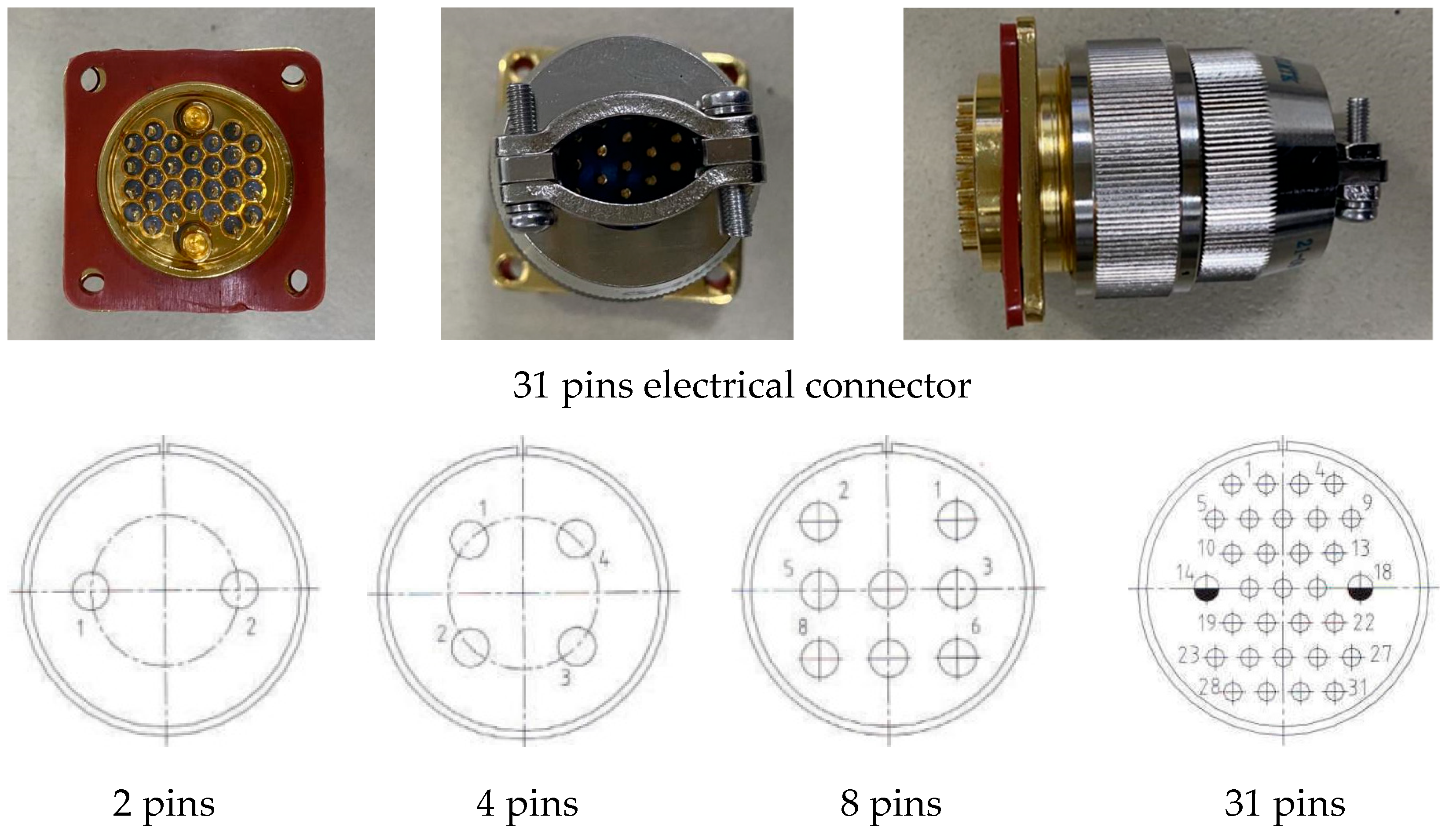
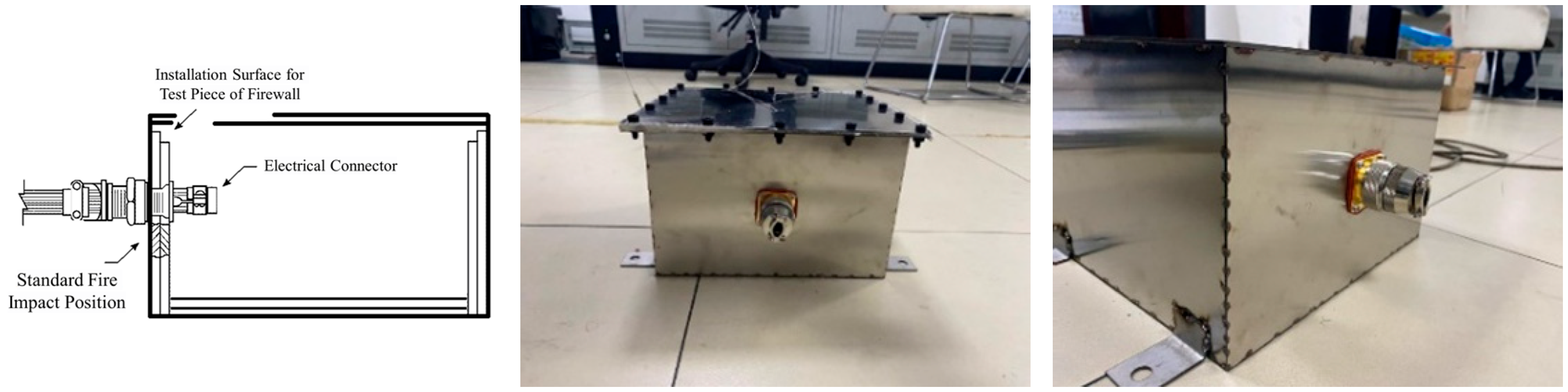
This experiment was designed to evaluate whether the functionality and integrity of electrical connectors with varying pin counts are affected when exposed to a high-temperature ignition source nearby. Additionally, the study examined the effectiveness of firewall protection on connectors installed with mounting surfaces, simulating actual operational conditions. The electrical connectors tested were commercially available models commonly used in aerospace applications. The connectors had contact pin counts of 2, 4, 8, and 31, as detailed in Table 1 and illustrated in Figure 1. A custom stainless steel plate measuring 230 mm × 254 mm × 167 mm, with a wall thickness of at least 0.38 mm, was fabricated to simulate a realistic physical environment, as shown in Figure 2. The primary function of this stainless steel plate is to prevent a hazardous quantity of air, fluids, or flames from escaping the designated fire zone and causing further damage to the aircraft’s internal electrical components. A hole was drilled in the center of the mounting surface on one side of the plate to assess the fire resistance performance of the electrical connector under actual fire conditions.

Table 1.
Composition and specification of electrical connector.

Figure 1.
Different types of electrical connectors.
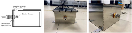
Figure 2.
Electrical connector with firewall.
2.2. Experimental Conditions
In conjunction with the 5 min functional failure assessment and the 15 min fire resistance evaluation, this experiment was designed with flame exposure durations of 3 min, 5 min, 10 min, and 15 min. The specific test conditions are detailed in Table 2.
Table 2.
Experimental condition.
2.3. Experimental Platform
2.3.1. Test Installation
The electrical connector test specimens were secured on the combustion test bench using a test fixture. Steel bars were employed to firmly position the electrical connectors at the center of the test fixture. The ignition point for the test was set at the center of the electrical connector. During the test, the distance between the burner’s conical outlet face and the surface of the test specimen was maintained at 102 mm ± 2 mm. The center of the electrical connector was positioned 25 mm ± 1 mm above the centerline of the burner outlet. For more details, refer to Figure 3, which illustrates the installation of the electrical connector fixing device.
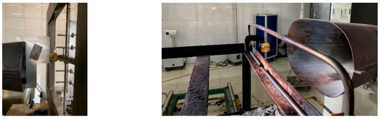
Figure 3.
Electrical connector fixing device installation.
2.3.2. Firewall Construction
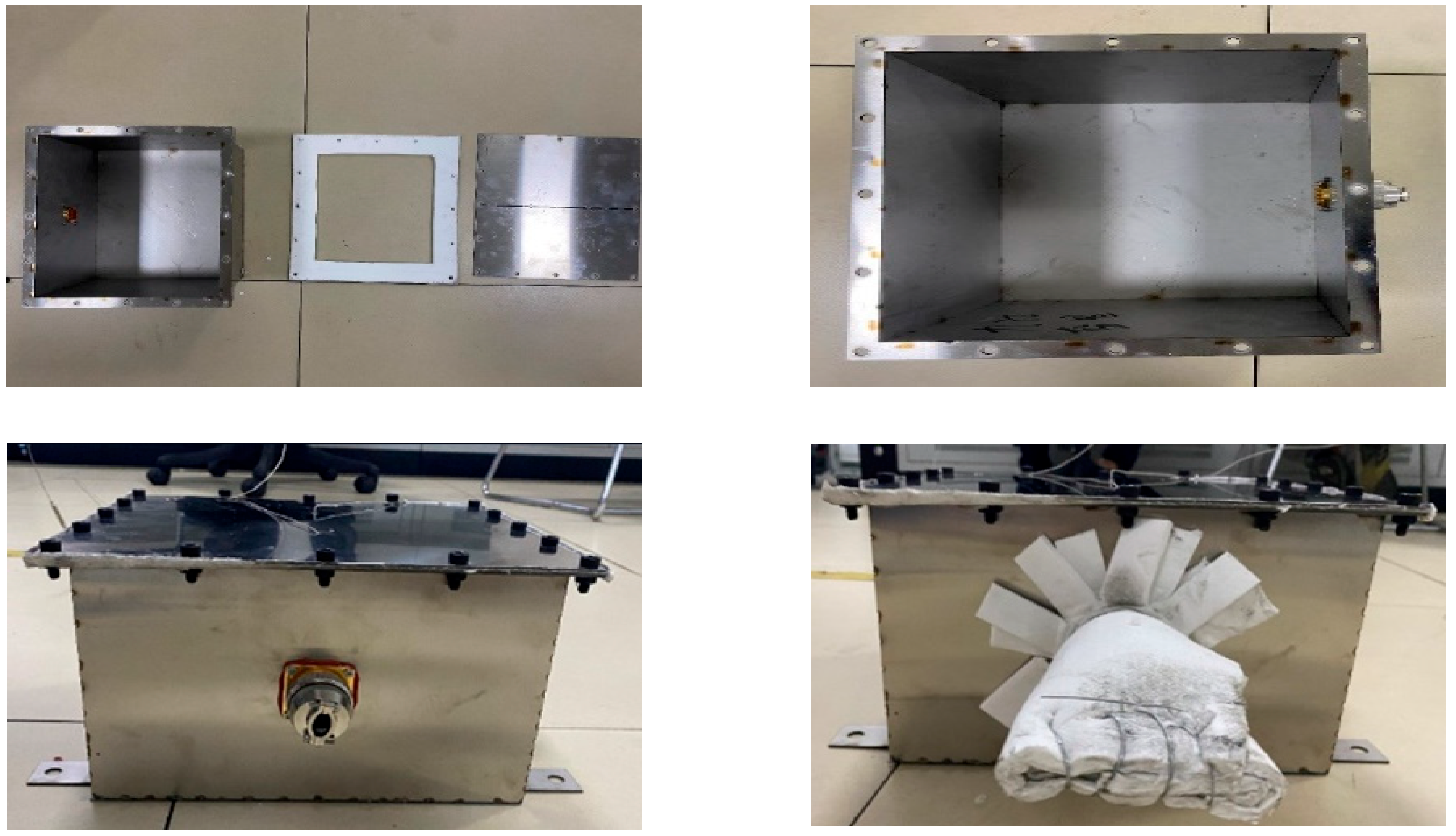
The experiment utilized a stainless-steel frame measuring 230 mm × 254 mm × 167 mm, with a wall thickness of at least 0.38 mm, to simulate an actual firewall. The firewall assembly consisted of three components: a firewall base, an insulating cotton gasket, and a firewall cover plate. A 31-pin electrical connector was installed within a pre-drilled passage on the side of the firewall assembly. For test conditions labeled as sequence 14 and sequence 15, two thermocouples were positioned along the firewall’s central axis at one-third and two-thirds of its length. The thermocouples were inserted to a depth of 83 mm from the upper surface (halfway between the top and bottom). As shown in Figure 4, the temperature data collected were used to assess the internal temperature changes within the firewall under fire exposure conditions. For sequence 15, additional layers of fireproof insulation were applied at the cable connection end to ensure that the electrical connection and cable end were protected from flame impact during the test.

Figure 4.
Electrical connector fixing device installation.
2.3.3. Experimental Equipment
The primary equipment used in the experiment was the Carlin oil burner, a gun-type burner designed to maintain a consistent oil pressure at the nozzle. The main test equipment and instruments are detailed in Table 3.
Table 3.
Test equipment and instruments.
2.4. Experimental Preparation
2.4.1. Subject Examination
Before the experiment, routine inspections were conducted on the test specimens to ensure they met the required performance standards. After passing these inspections, the specimens were connected to the test fixtures and detection equipment, ensuring good electrical continuity. The wires passing through the electrical connectors were connected to form a closed circuit, with the connector casing grounded during the test. The specimens were then inspected sequentially for appearance, conductivity, and insulation. The appearance of the cables was checked visually. If the appearance was intact, with no damage and complete labeling, it was deemed satisfactory. Conductivity was assessed using a micro-ohmmeter to measure the resistance between the pathways at both ends of the electrical connector. If the resistance was less than 500 mΩ under normal temperature and pressure, the conductivity was considered acceptable. Insulation was tested by measuring the insulation resistance between any non-connected pathways of the connector’s contact pins and between any non-connected contact pairs and the casing. If no resistance was detected, the insulation was deemed satisfactory. The pre-test inspection records are detailed in the accompanying Table 4.
Table 4.
Check items before experiment.
2.4.2. Subject Examination Calibration of Experimental Equipment
The distance between the burner’s conical outlet and the surface of the test specimen was maintained at 102 mm ± 2 mm, with the flame temperature required to meet 1093 ± 83 °C, and the heat flux density exceeding 10.6 W/cm2. The position of the test setup and the flame temperature and heat flux were calibrated using a distance calibration gauge, a standard heat flux meter, and a thermocouple rake, as shown in Figure 5. Before the test, the center of the electrical connector was adjusted to be 25 mm ± 1 mm above the centerline of the burner’s outlet.
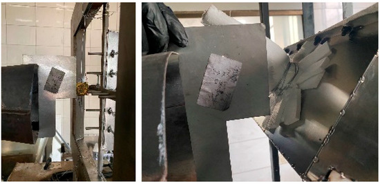
Figure 5.
Position calibration.
The thermocouple rake, consisting of seven thermocouples, was positioned 100 mm ± 2 mm in front of the burner’s outlet face, with the thermocouple tips placed 25 mm ± 1 mm above the centerline of the burner’s outlet. Similarly, the heat flux meter was positioned 100 mm ± 2 mm in front of the burner’s outlet face, with its centerline 25 mm ± 1 mm above the centerline of the burner’s outlet. The flame impact distance and height were determined using a distance calibration gauge. The burner was placed in the preheating position and ignited, with a preheating duration of 2 min. After preheating, the burner was moved to the thermocouple rake calibration position to confirm that the temperature reached 1093 ± 83 °C. The thermocouple rake was then moved back to the preheating position, and the heat flux meter was placed in the testing position to confirm that the heat flux value was at least 10.6 W/cm2.
3. Results and Analysis
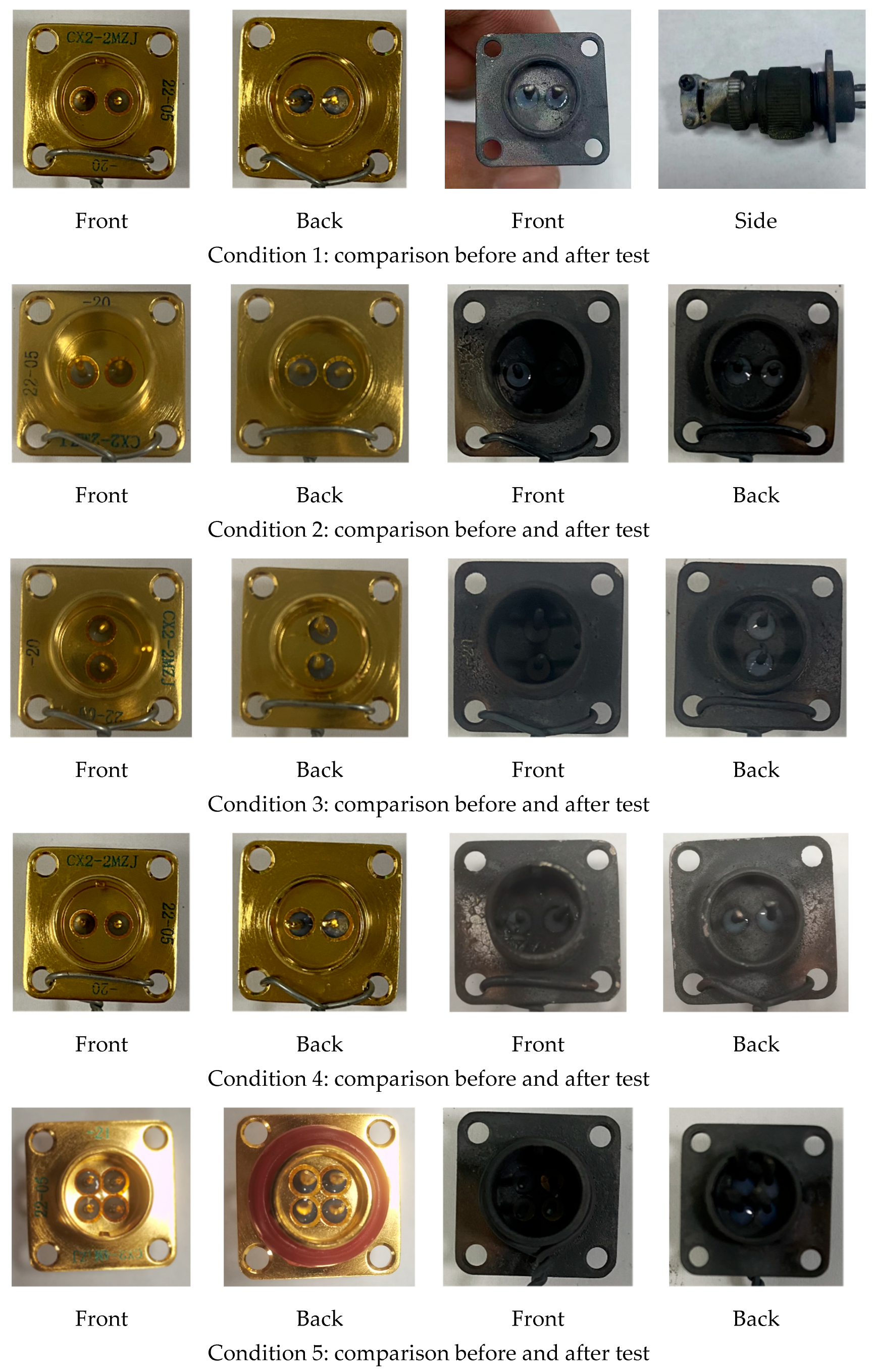
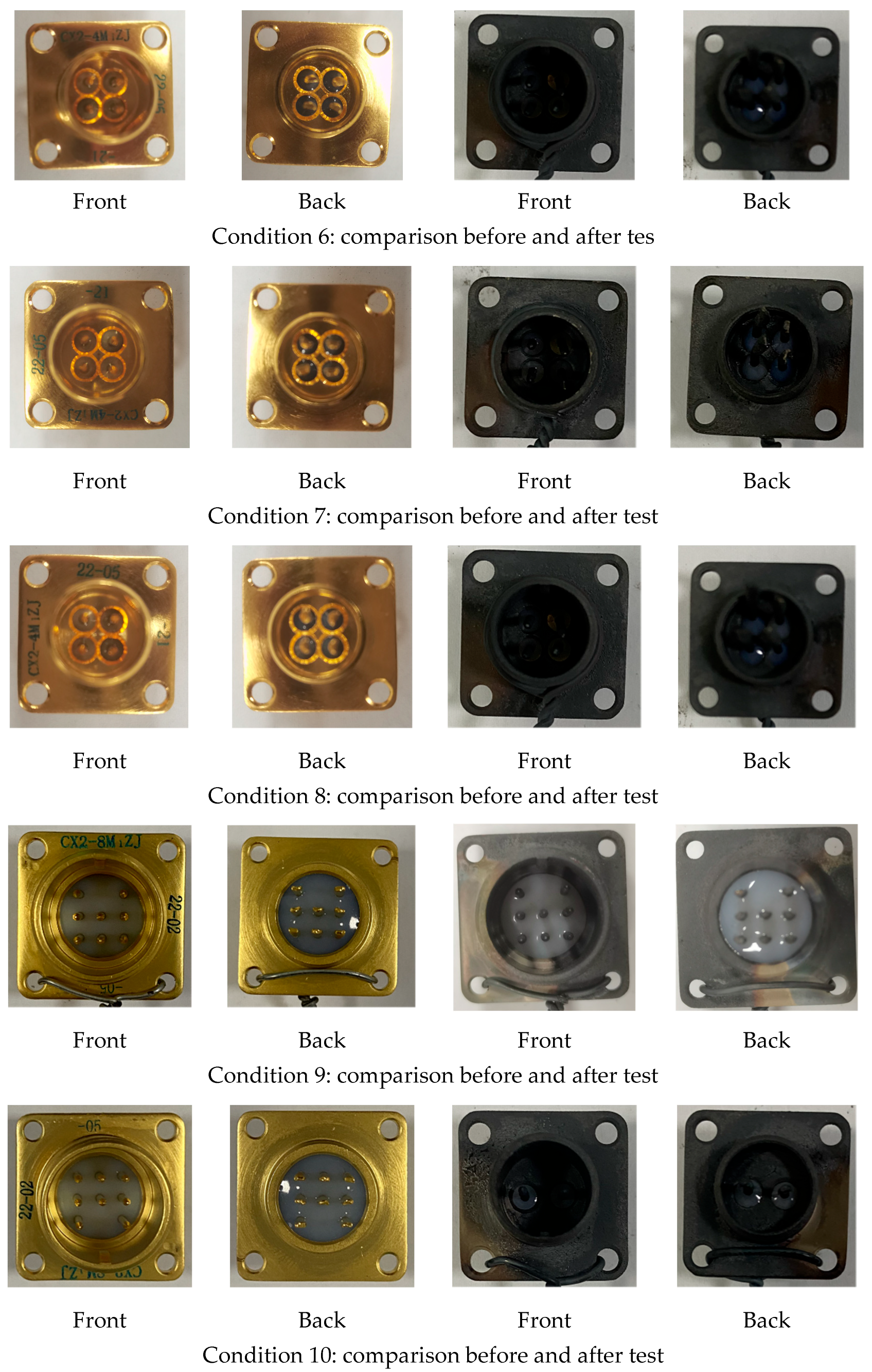
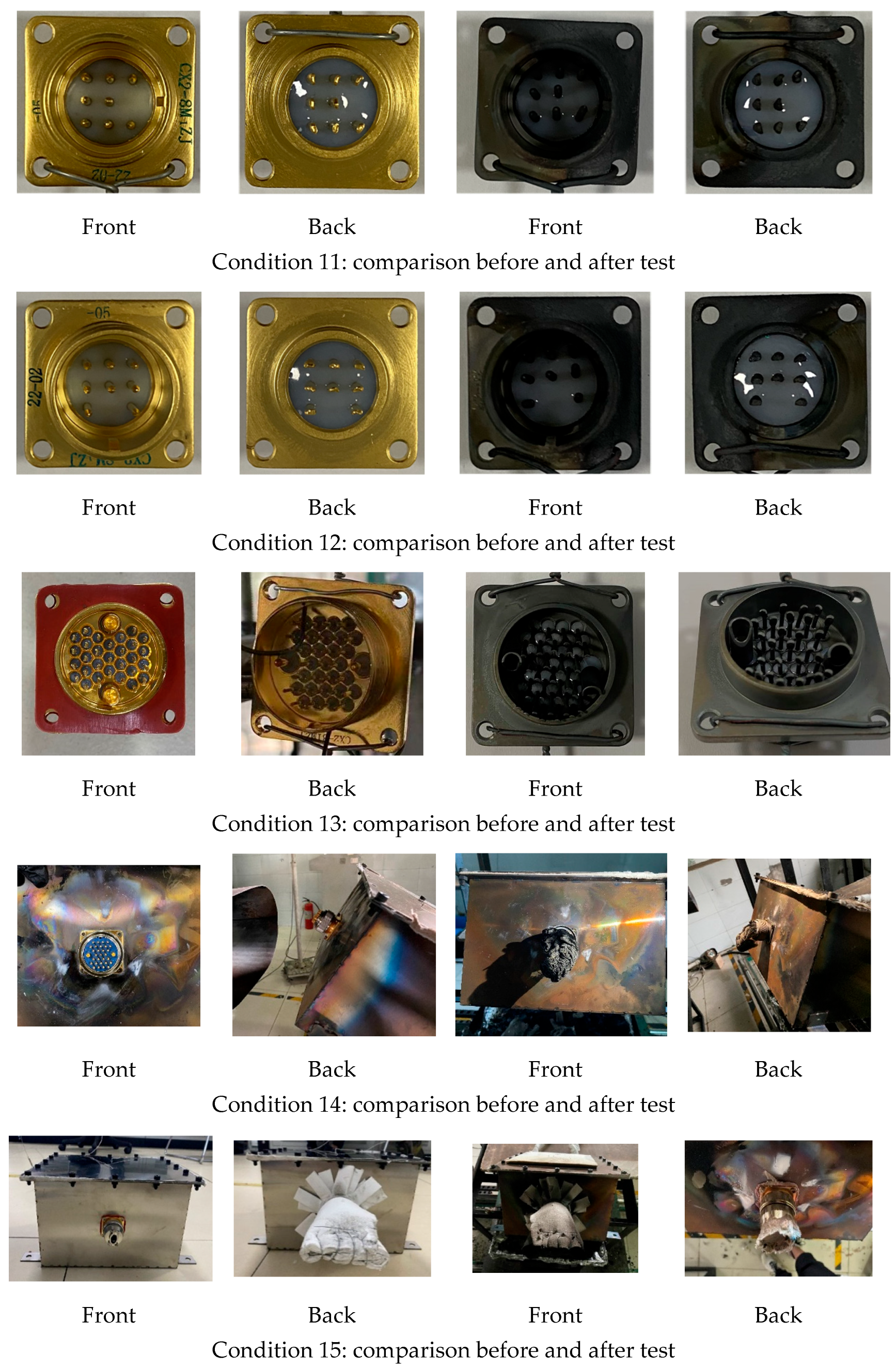
For specimens numbered 1 to 12, after undergoing fire resistance tests for durations ranging from 3 to 15 min, the conductivity between the contact pins of the electrical connectors remained satisfactory, with the conduction resistance at normal temperature and pressure measuring less than 500 mΩ. The insulation resistance between the contact pins, as well as between the contact pins and the casing, was also within acceptable limits, confirming satisfactory insulation performance. Specimen number 13 showed acceptable conductivity, but the contact between the pin close to the inner wall and the casing led to insulation failure, resulting in non-compliance with insulation standards. For specimen number 14, which lacked fireproof insulation, severe material melting and dripping occurred after the 15 min fire resistance test, compromising the connector’s structural integrity. The contact pins were severed, leading to a loss of conductivity, and unintended contact between the non-connected contact pins caused insulation failure. Specimen number 15, which was wrapped in fireproof insulation, exhibited melting after the 15 min fire resistance test but retained its structural integrity. The specimen continued to meet the requirements for both conductivity and insulation, the details of which are shown in Figure 6.

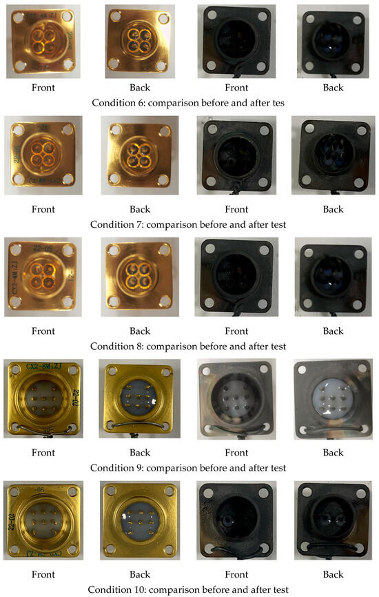

Figure 6.
Comparisons before and after test.
The fire resistance performance of the electrical connectors was evaluated based on flame penetration, conductivity, and circuit integrity. Throughout the duration of the test, no flame should be detected on the protected side of the firewall, indicating no burn-through or sustained combustion. The electrical connectors were tested to ensure circuit continuity through the contact pins, with no signs of short circuits between contact points or between contact points and the casing. During the test, it was observed that the electrical connectors did not exhibit any sustained combustion. For specimens equipped with a firewall (numbers 14 and 15), no flame, burn-through, or sustained combustion was detected on the protected side of the firewall. After the test, the specimens were inspected sequentially for appearance, conductivity, and insulation. The results of these inspections are summarized in Table 5, “Summary of Post-Test Inspection Items for Electrical Connectors”. Conductivity was assessed using a micro-ohmmeter to measure the resistance between the pathways at both ends of the electrical connector. If the conduction resistance was less than 500 mΩ at normal temperature and pressure, the conductivity was considered acceptable. Insulation was evaluated by measuring the insulation resistance between any non-connected contact pins and between any non-connected contact pairs and the casing. If no resistance was detected, the insulation was deemed acceptable.
Table 5.
Electrical connector contact pin density and fire performance analysis.
As the number of contact pins increases, the distance between the pins and between the pins and the casing decreases. Under prolonged exposure to high-temperature flames, the non-metallic materials are prone to softening and deformation, which can result in contact between the pins or between the pins and the casing, leading to insulation failure in the electrical connectors. To further characterize the relationship between the number of pins and fire resistance performance, the concept of “pin density” for electrical connectors was introduced. Pin density refers to the total number of contact pins per square centimeter of the connector. By comparing the pin density of these electrical connectors, it was found that insulation failure tends to occur when the pin density ranges between 4.53 and 5.04 pins per square centimeter. In the analysis and quantitative evaluation of weak points, particular attention should be given to electrical connectors with a pin density greater than 5 pins per square centimeter (pins/cm2). The non-metallic material used for the cable-end connection (female connector) of the electrical connector is PSU, which is a copolymerized composite modified from PSU resin and transparent activator liquid using a twin-screw extruder. Although this PSU material has been successfully applied in various military and aerospace systems, the experimental results indicate that under flame impact conditions, the female connector is highly prone to high-temperature foaming and carbonization, leading to the detachment of contact pins and resulting in insulation failure. The non-metallic material used for the casing-end connection (male connector) is a specialized heat-resistant silicate material, which maintains structural integrity well under flame impact conditions. When the cable-end connector (female connector) is provided with fire protection using insulating and heat-resistant materials, as simulated in this experiment with fireproof cotton, it helps the electrical connector retain its functionality under flame impact. To further evaluate the fire resistance performance of the electrical connectors, three thermocouples were placed on the front and back of the 31-pin connector (specimen number 13) to monitor temperatures at the contact pins, the inner wall, and the outer wall on the non-flame-exposed side. The temperature data collected were used to assess the temperature variation trends of the test specimen under fire exposure conditions, as detailed in Figure 7. The test curves indicate that after the start of flame exposure, the wall temperature of the connector rapidly increased, reaching thermal equilibrium at around 100 s. The equilibrium wall temperatures within the fire-exposed area of the connector ranged between 900 °C and 1000 °C. The temperatures on the connector’s wall surfaces (monitored by thermocouples 2 and 3) were close to the flame temperature, while the temperature at the contact pins (monitored by thermocouple 1) was recorded at 900 °C. To further assess the protective performance of the firewall on the electrical connectors, two thermocouples were placed along the firewall’s central axis at one-third and two-thirds of its length in the test conditions for specimens number 14 and 15. The thermocouples were positioned at a depth of 83 mm from the upper surface (halfway down). The temperature data collected were used to evaluate the temperature variation trends within the firewall under fire exposure conditions. The test curves indicate that the internal air temperature within the firewall in the fire-exposed area ranged between 520 °C and 570 °C. For this experiment, a stainless-steel plate measuring 230 mm × 254 mm × 167 mm, with a wall thickness of at least 0.38 mm, was custom-made to simulate a realistic physical environment, following the dimensions of the AGB electrical connector firewall. The thermocouples were placed along the central axis at one-third and two-thirds of the firewall’s length, with a placement depth of 83 mm from the upper surface (halfway down).
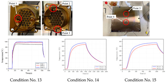
Figure 7.
Temperature curve.
4. Discussion and Conclusions
This experiment was conducted to evaluate the ability of electrical connectors, both independently and when passing through a firewall, to prevent flames from penetrating to the protected side of the firewall. The fire resistance test report for the electrical connectors was prepared in accordance with ISO 2685-1998, and fire resistance tests were conducted to determine whether the connectors can function normally in a flame environment and to identify any potential damage that could lead to connector failure due to flame exposure. The test aimed to assess the fire resistance performance of electrical connectors, both on their own and when protected by a firewall, by evaluating their ability to resist functional failure under a standard flame generated by a standard burner over a specified period. The temperature variation data collected from the electrical connectors and the firewall under flame impact provided valuable insights for the weak point analysis of typical engine components in fireworthiness tests. The experiment involved measuring the temperature parameters of different pin-count electrical connectors and those protected by a firewall under simulated engine conditions. These measurements were conducted under a standard flame generated by a standard burner for 15 min.
The experimental results indicate the following:
- As the number of contact pins increases, the distance between the pins and between the pins and the casing decreases. Under prolonged exposure to high-temperature flames, the non-metallic materials are prone to softening and deformation, leading to contact between the pins or between the pins and the casing, resulting in insulation failure. Electrical connectors made from silicate materials with a pin density between 4.53 and 5.04 pins/cm2 are prone to insulation failure. In weak point analysis and quantitative evaluation, attention should be focused on connectors with a pin density greater than 5 pins/cm2.
- The results show that under flame impact, the female connector is highly susceptible to high-temperature foaming and carbonization, leading to the detachment of contact pins and subsequent insulation failure. In contrast, the male connector, used for casing connections, maintains its structural integrity well under flame impact. Therefore, structural areas exposed to flame impact should be a focal point in weak point analysis and quantitative evaluation.
- Providing fire protection for the cable-end connector using insulating and heat-resistant materials helps to maintain the functionality of the connector under flame impact. Therefore, the presence of fire protection measures at the cable connection end of the connector should also be included in the weak point analysis evaluation.
- For this experiment, a stainless-steel plate measuring 230 mm × 254 mm × 167 mm, with a wall thickness of at least 0.38 mm, was custom-made to simulate a realistic physical environment based on the dimensions of the AGB electrical connector firewall. When the connector was directly exposed to flames, the equilibrium wall temperature within the fire-exposed area ranged between 900 °C and 1000 °C. With the firewall providing physical isolation, the internal air temperature within the firewall ranged between 520 °C and 570 °C. These data provide valuable support for the selection of non-metallic materials in future fireworthiness compliance design and validation of typical engine components.
Author Contributions
Conceptualization, B.W.; methodology, K.W.; validation, T.Z.; formal analysis, T.W.; investigation, K.W.; resources, Z.S.; data curation, T.Z.; writing—original draft preparation, B.W.; writing—review and editing, B.W.; visualization, K.W.; supervision, Z.S.; project administration, F.X.; funding acquisition, Z.S. All authors have read and agreed to the published version of the manuscript.
Funding
This research was funded by National Science and Technology Major Project (J2019-VIII-0010-0171).
Data Availability Statement
The data used in this paper are obtained from literature references and experimental tests. If needed, please contact the relevant authors for access.
Conflicts of Interest
Author Kai Wang was employed by the company AECC Commercial Aircraft Engine. The remaining authors declare that the research was conducted in the absence of any commercial or financial relationships that could be construed as a potential conflict of interest.
References
- International Electrotechnical Commission (IEC). IEC 60695-11-10: Fire Hazard Testing—Part 11-10: Test Flames—Procedure for Testing the Resistance to Fire of Materials Used in Electrical Connectors; IEC: Geneva, Switzerland, 2013. [Google Scholar]
- Society of Automotive Engineers (SAE). SAE J1756: Determination of the Fogging Characteristics of Interior Automotive Materials; SAE: Warrendale, PA, USA, 2013. [Google Scholar]


Disclaimer/Publisher’s Note: The statements, opinions and data contained in all publications are solely those of the individual author(s) and contributor(s) and not of MDPI and/or the editor(s). MDPI and/or the editor(s) disclaim responsibility for any injury to people or property resulting from any ideas, methods, instructions or products referred to in the content. |
© 2025 by the authors. Licensee MDPI, Basel, Switzerland. This article is an open access article distributed under the terms and conditions of the Creative Commons Attribution (CC BY) license (https://creativecommons.org/licenses/by/4.0/).