Next Article in Journal
An Experimental Study for Localization Using Lidar Point Cloud Similarity
Previous Article in Journal
Mitigating Environmental Risks: Efficient Removal of Metronidazole from Pharmaceutical Wastewater Using Functionalized Graphene Membrane
 
 
engproc-logo
Article Menu

Article Menu

Proceeding Paper

Co-Simulation and Platform Design of Airfoil Actuator Performance †

AVIC Qingan Group Co., Ltd., Xi’an 710003, China
Presented at the 2nd International Conference on Green Aviation (ICGA 2024), Chengdu, China, 6–8 November 2024.
Eng. Proc. 2024, 80(1), 23; https://doi.org/10.3390/engproc2024080023
Published: 2 January 2025
(This article belongs to the Proceedings of 2nd International Conference on Green Aviation (ICGA 2024))

Abstract

The airfoil actuator is a necessary general component of modern aircraft, and the design of the airfoil actuator is a process that needs to be iterated repeatedly. It is difficult for a single modeling simulation to meet the requirements of multi-dimensional design. By designing a platform software to meet the requirements of multi-model co-simulation, the co-simulation can more accurately describe the detailed situation of a system through comparative analysis of simulation results. This paper provides a set of systematic and complete methods for the performance co-simulation of the airfoil actuator, and the data obtained from the analysis provide a reference for the design of the airfoil actuator.

1. Introduction

The airfoil actuator is a common component necessary for the flaperon/slat extension/recovery of modern aircraft, with its performance directly affecting the airfoil’s operating speed, flight stability, flight control performance [1], and so on.
ADAMS (2019, Automatic Dynamic Analysis of Mechanical Systems, Mechanical Dynamics Inc.) is based on computational multi-body system dynamics and is used for system kinematics, dynamic analysis, and simulation. LMS Imagine.Lab AMESim (2016, Advanced Modeling Environment for performing Simulation of engineering systems) is an advanced platform for modeling and simulation of complex systems in multidisciplinary fields [2]. The model bus can be used as a co-simulation platform [3]. The co-simulation of the two software not only includes the single-point simulation analysis of the whole life cycle of the product on the timeline but also emphasizes the co-simulation analysis of the unified product object on the system level based on different personnel/tools at the same point in time. The co-simulation can make the performance simulation of the airfoil actuator more real and accurate.

2. Establishment of Joint Simulation Model of Airfoil Actuator

The actuator is mainly composed of a motor, a hydraulic pump, a booster tank, an actuator cylinder, and a combination valve. The actuator is powered by the system, the controller drives the motor to rotate, and the motor rotates to drive the pump to output high-pressure oil to drive the actuator cylinder piston output. The actuator cylinder has a built-in LVDT [4] line displacement sensor, which feedbacks the piston rod position to the controller in real time to realize the flaperon/slat extension/recovery work.

2.1. Mathematical Model of Parametric Airfoil Actuator

2.1.1. BLDC Motor

The motor converts electrical energy into mechanical energy, outputs a specified speed, torque, and steering, and can feed back motor current, speed, and position signals to the controller through sensors. The working principle of the motor is explained by several formulas [5]:
① Rotor voltage balance equation
U a = R a i a + L a d i a d t + E a
U a —Armature terminal voltage, V;
E a —Induced electromotive force, V;
R a —Total resistance of the armature circuit, Ω;
L a —Armature inductance, H;
i a —Armature current, A armature inductance, H.
② Rotor-induced potential
E a = K e × Ω a
K e —Potential constant, V·s/rad;
Ω a —Rotor speed, rad/s.
③ Torque balance equation
T e T L = J m d Ω a d t + B m Ω a
T e —Electromagnetic torque, N·m;
T L —Total load torque, N·m;
T L = T 0 + T f , T 0 —No-load resistance torque, T f —load torque;
J m —Moment of inertia, Kg·m2;
B m —Damping coefficient.
④ Electromagnetic torque of rotor
T e = K t ×   i a
K t —Torque constant, N·m/A.

2.1.2. Hydraulic Pump

A hydraulic pump is used to convert mechanical energy into hydraulic energy, output a certain pressure and flow of hydraulic oil, and drive the actuator cylinder to overcome the load for reciprocating action.
① The flow calculation formula of the hydraulic pump [6] is:
Q p u m p = n   ×   D p
n—Motor speed, r/min;
D p —Hydraulic pump displacement, mL/r.
② The output torque of the hydraulic pump is calculated as follows:
T o u t = P o u t P i n · D p 2 · π
P o u t —Hydraulic pump outlet pressure, MPa;
P i n —Hydraulic pump oil-return port pressure, MPa.

2.1.3. Hydraulic Jack

The actuator cylinder adopts the structure of an equal rod cavity, and the wire displacement sensor is installed in the actuator cylinder, which can detect the piston displacement of the actuator cylinder. Since the actuator is an equal cavity form, the output force and velocity formula of the actuator are:
F = P · A · η m
V = Q A · η v
△P—The pressure difference between the two chambers of the actuator cylinder, MPa;
A—Actuator cylinder two-cavity area, mm2;
Q—Actuator inlet flow, L/min;
η m —The mechanical efficiency of the actuator;
η v —The volumetric efficiency of the actuator.

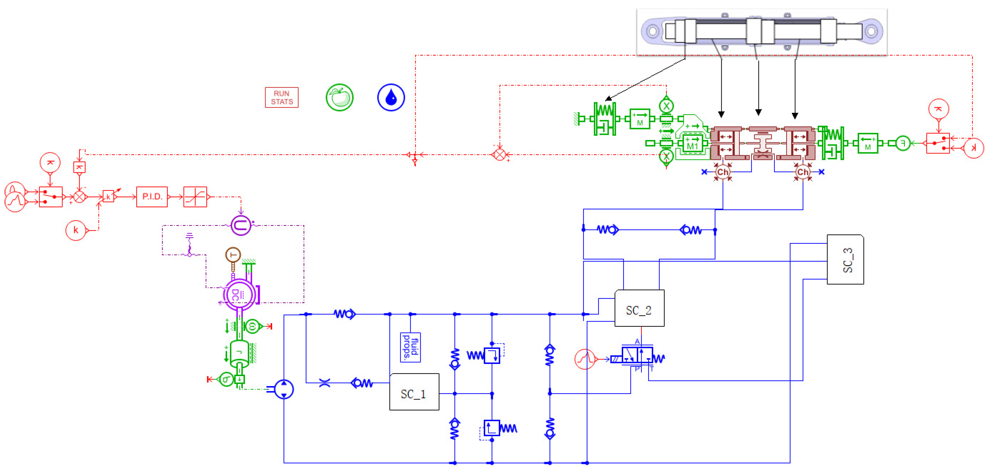
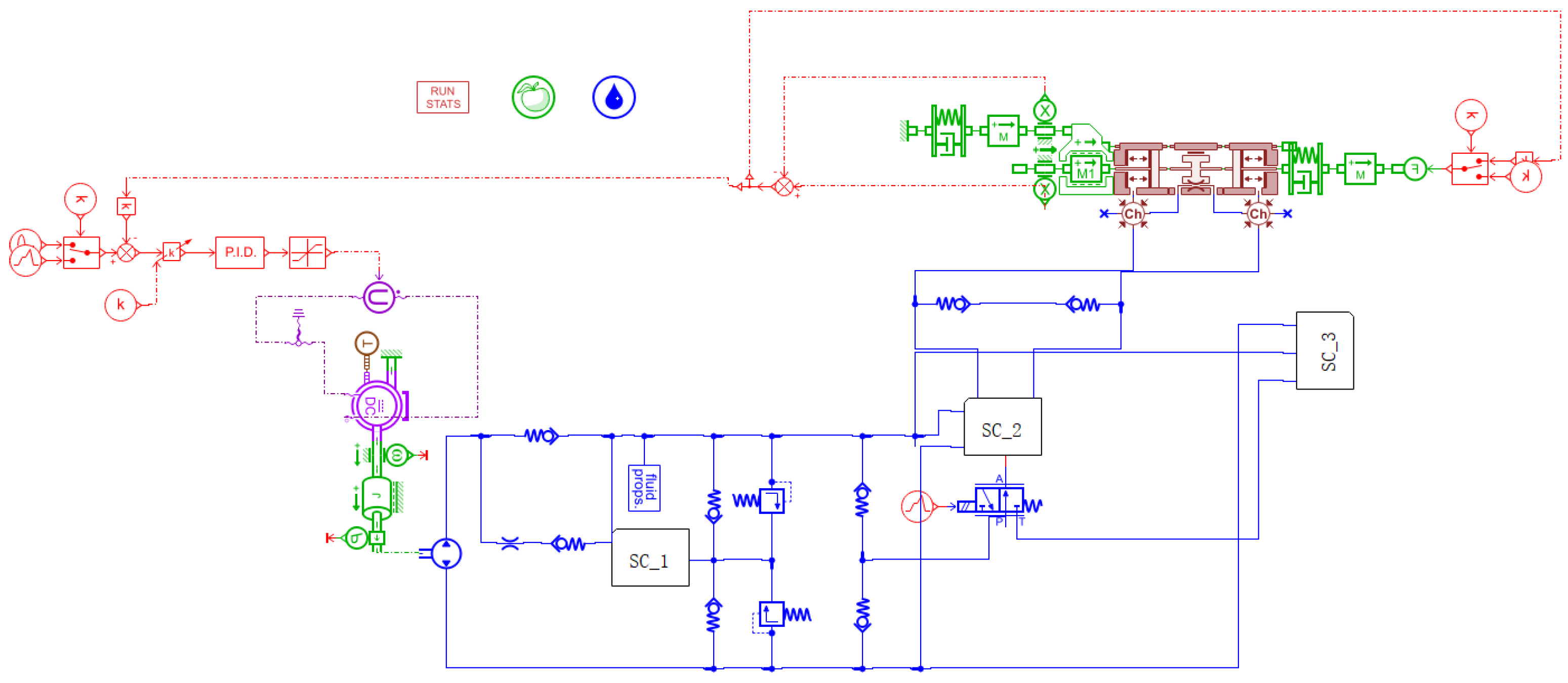
2.2. Establishment of Hydraulic Model of Airfoil Actuator

The hydraulic model of the wing actuator is established based on AMESim, and the flapper/slit wing actuator model is established by using the signal component design library, hydraulic component design library, and mechanical component design library in AMESim. The AMESim model of the combined valve-controlled actuator and the ADAMS co-simulation model of the combined valve-controlled actuator are built. The principle and process of joint simulation are introduced with an example of an equal rod cavity actuator.
The airfoil actuator drives the actuator barrel, which requires the actuator barrel to overcome the load and reciprocate according to the requirements under the hydraulic source with a certain pressure and flow. Figure 1 shows the relationship between the actuator structure and the model.

3. Actuator Co-Simulation Analysis

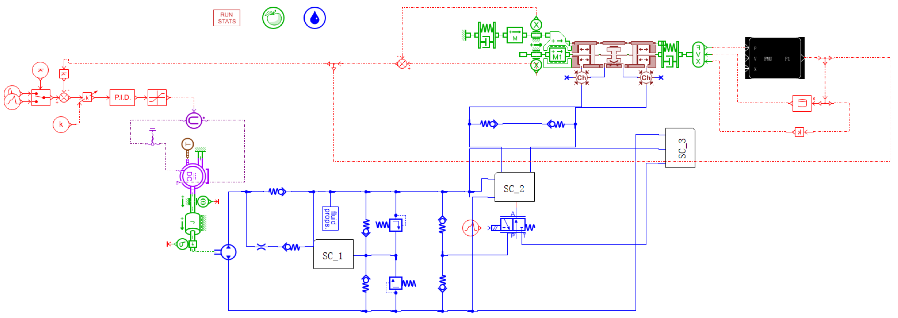
3.1. Actuator Co-Simulation

There are four co-simulation modes for ADAMS and AMESim, that is, the ModelExchange1.0\2.0 and the Co-simulation1.0\2.0FMU. In this paper, Model Exchange2.0FMU was used. In the co-simulation process, the system flow and pressure were calculated by AMESim, the actuating displacement and output torque were calculated by ADAMS, and the data were exchanged by the model bus. The co-simulation model is shown in Figure 2.

3.2. Analysis of Simulation Result

Taking the combination valve-controlled equal-rod cavity actuator as an example, the co-simulation of the actuator ADAMS model and the AMESim model of the system and the simulation of a single AMESim system are compared and analyzed. The wing actuator counterweight is 1000 Kg.

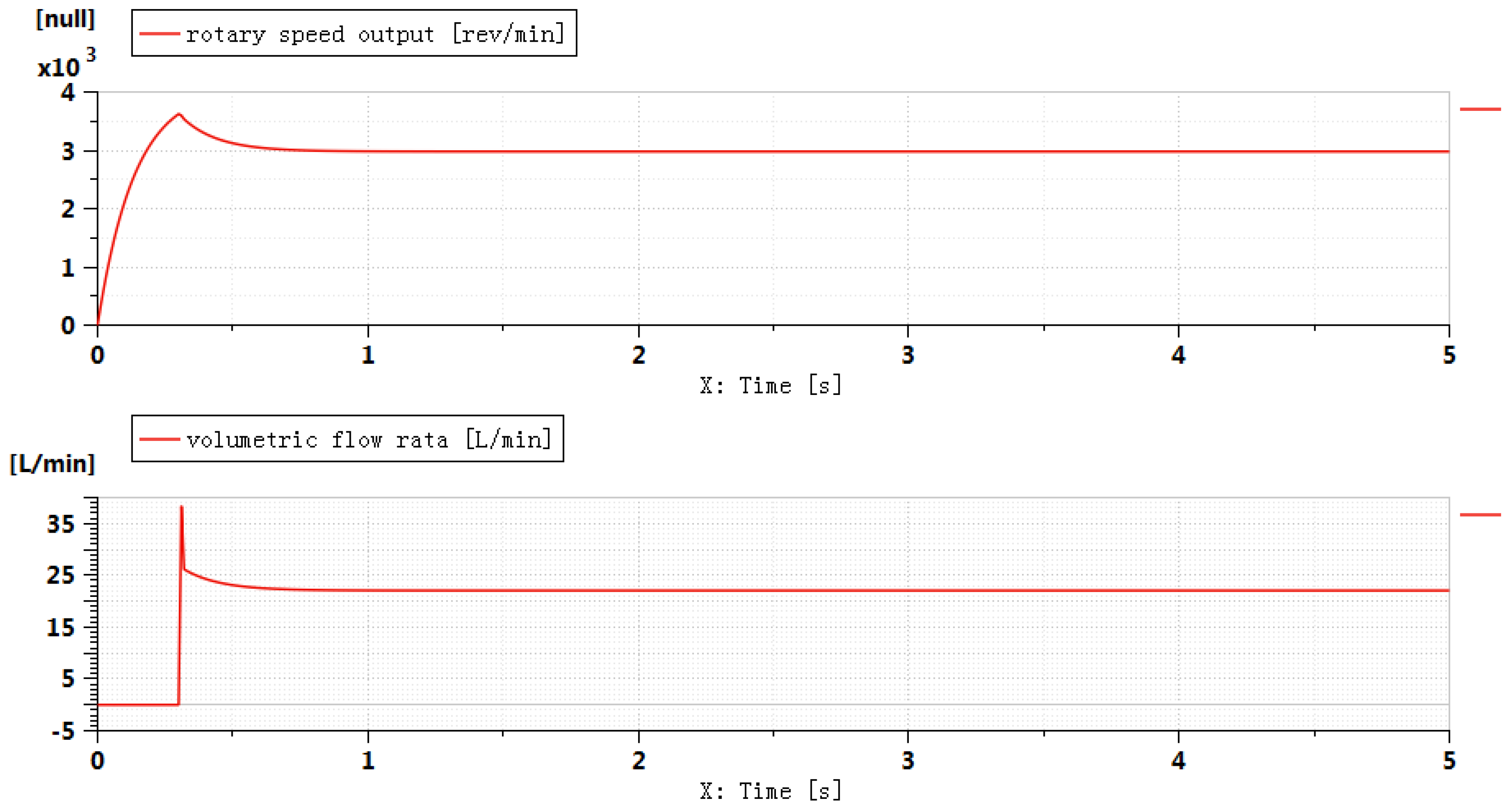
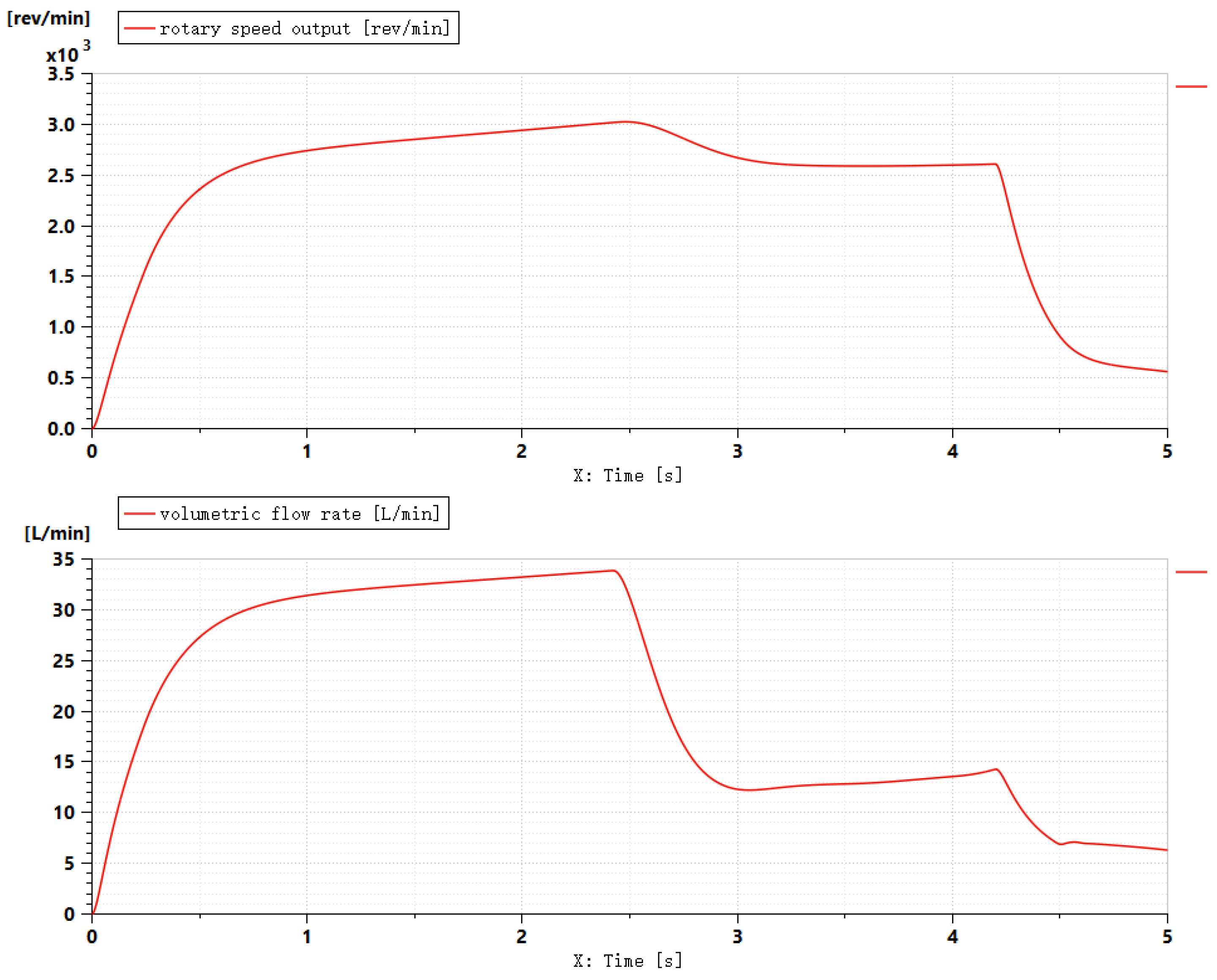
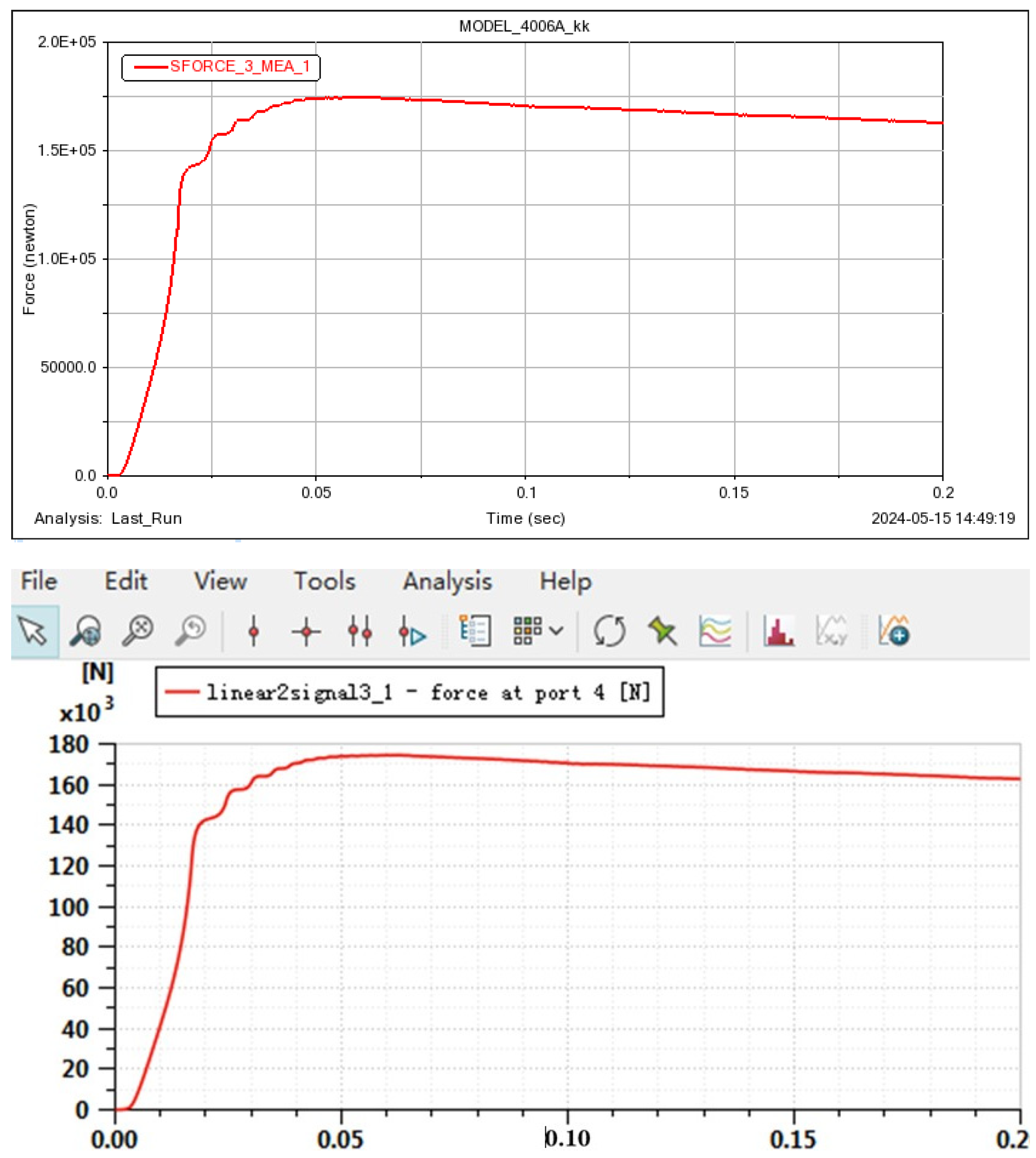
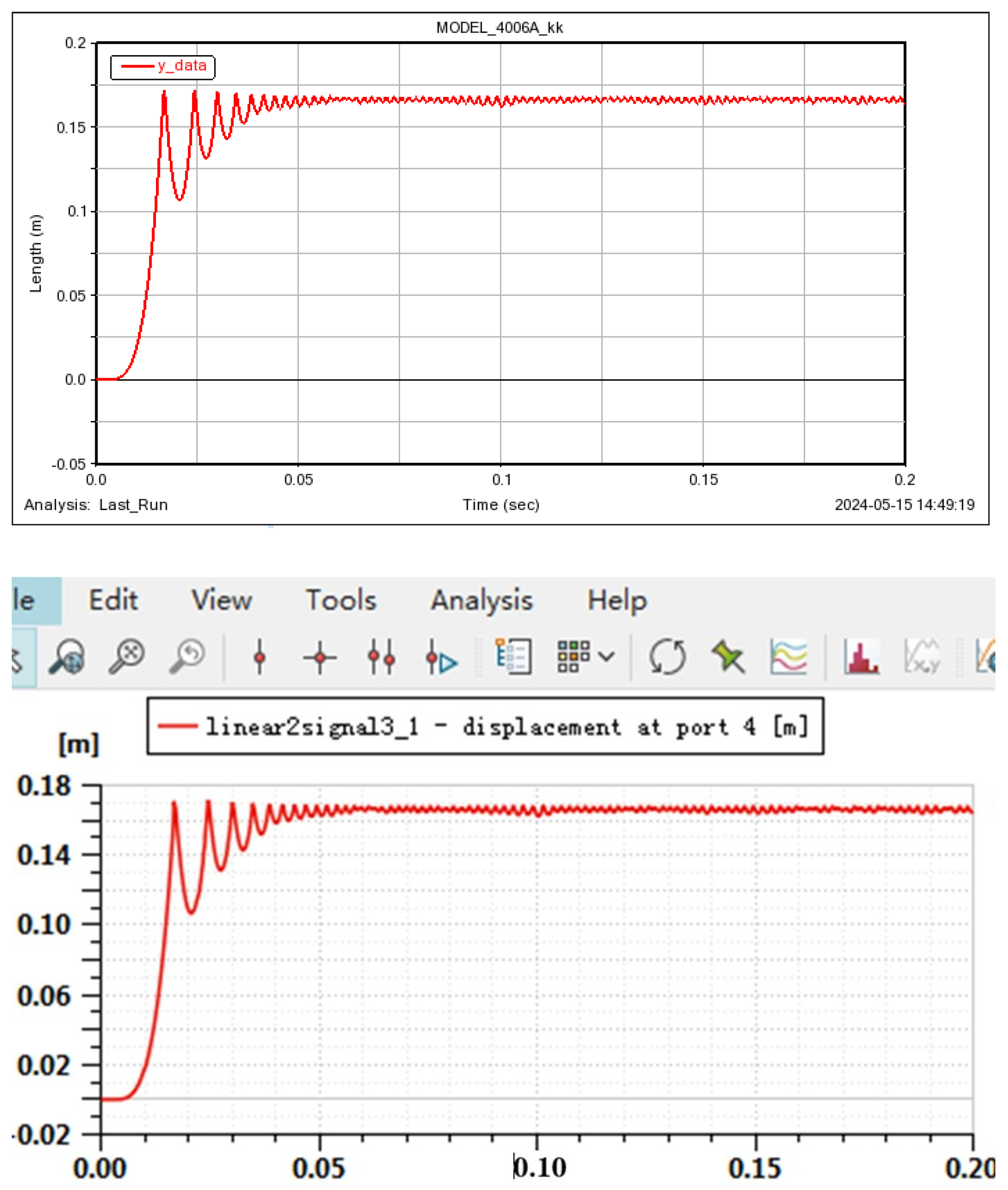
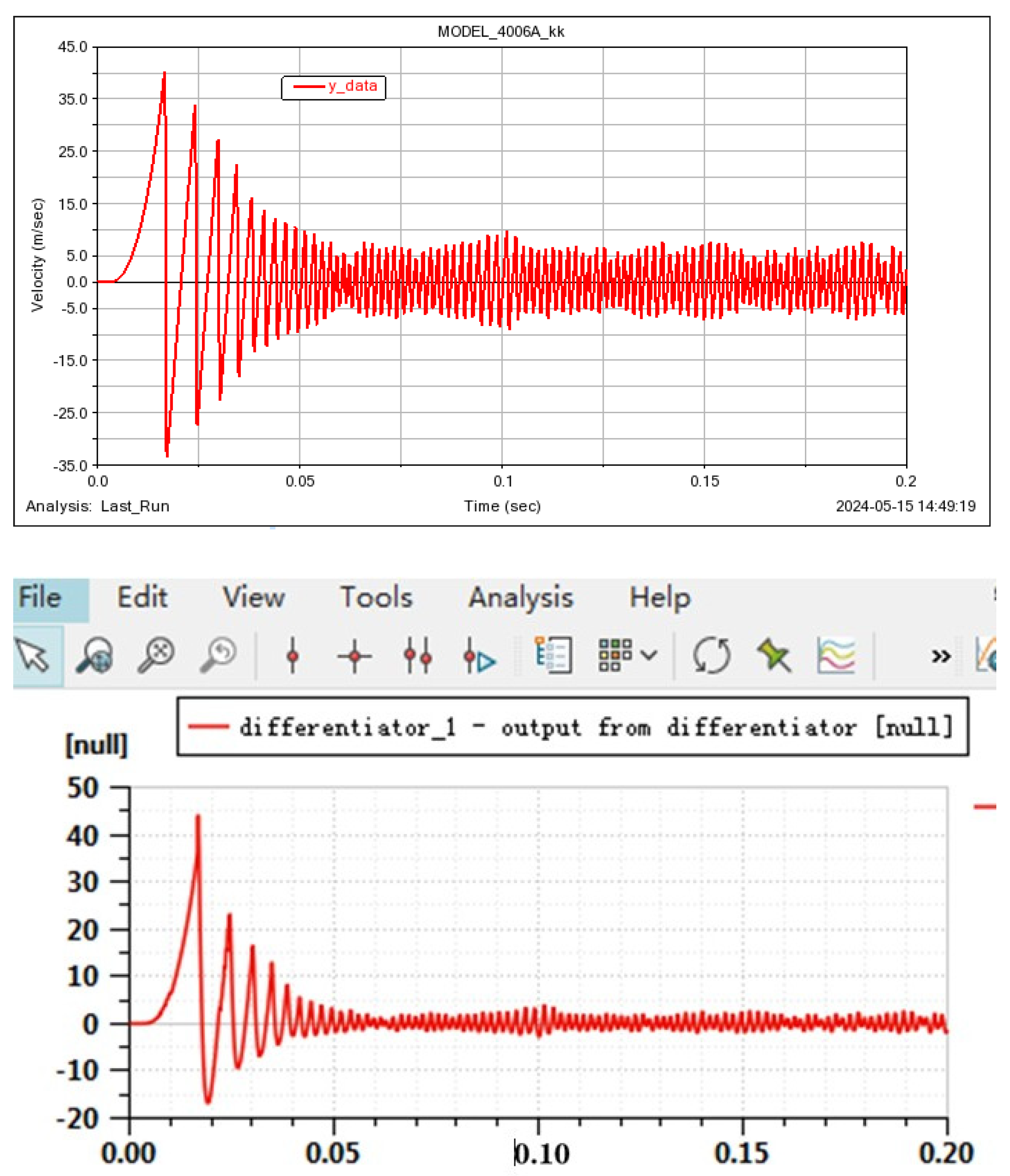
3.2.1. Single Simulation Result

The airfoil actuator system model shown in Figure 3 is built in AMESim, and each system component is connected through the cross-linking relationship between the systems.
The simulation results are shown below. It can be seen that the actuator has no feedback process, which is not enough to reproduce the real working conditions of the actual system. The Movement process of wing actuator. is shown in Figure 4.
As can be seen from Figure 5, there is a lack of actuator force feedback. The results were not accurate enough.
The pump speed is stable at 3000 rev/min/, and the system flow is 22.58 L/min. Because the system does not change with the load’s force feedback, the output power of the power supply system is constant. Therefore, joint simulation is needed to observe the effect of dynamic feedback on the system.

3.2.2. Co-Simulation Result

The motor drives the pump to supply oil to the system, and the actuator drives the load movement through the control of the combined servo valve. In the actuator cylinder mechanism, the slide block and the piston are subjected to the system liquid pressure, and the servo valve is adjusted by the load movement displacement and speed feedback. In the AMESim, ADAMS, and airfoil actuator joint virtual test subsystem, the AMESim inputs a force to the airfoil actuator joint virtual test subsystem, and the airfoil actuator joint virtual test system transfers the force to ADAMS. ADAMS inputs the load displacement into the wing actuator joint virtual test subsystem, and the wing actuator joint virtual test subsystem inputs the displacement into AMESim. The Speed and flow of electric pump is shown in Figure 6.
The output power of the power supply system changes with the flow of the load movement. As the speed decreases, so does the system flow. The ADAMS (top) and AMESim (bottom) actuator forces is shown in Figure 7. The ADAMS (top) and AMESim (bottom) piston rod travel is shown in Figure 8. The Piston rod speed in Adams (top) and AMESim (bottom) is shown in Figure 9.

3.3. Software Design

The virtual test platform has two basic functions, namely:
(1) It can configure all parameters required for co-simulation and can configure and synchronize the simulation step size of the collaborative software;
(2) It can be compatible with multiple collaborative software co-simulations, as well as with FMU and the dynamic link library (*.dll file) import function.

4. Summary

Taking the airfoil actuator as an example, in the process of building a hydraulic model of an airfoil actuator and multi-body dynamics modeling of an actuator cylinder, co-simulation analysis and simulation platform design are introduced. It provides a systematic and complete method for the co-simulation performance of the wing actuator. The data obtained from the analysis provide a reference for the design of the aerofoil actuator.

Funding

This research was not funded.

Data Availability Statement

The data that support the findings of this study are available from the corresponding author upon reasonable request.

Conflicts of Interest

The author is employed by the company AVIC Qingan Group. The author declares that the research was conducted in the absence of any commercial or financial relationships that could be construed as a potential conflict of interest. The [AVIC Qingan Group in affiliation and funding] had no role in the design of the study; in the collection, analyses, or interpretation of data; in the writing of the manuscript, or in the decision to publish the results.

References

  1. Xiao, Y.; Wang, F.; Sun, P. Numerical simulation of two-dimensional plain flap ground effect based on NACA4412 airfoil. J. Phys. Conf. Ser. 2024, 2756, 012049. [Google Scholar] [CrossRef]
  2. Wang, C.; Lin, W.; Lin, X.; Wu, T.; Meng, Z.; Cai, A.; Xu, Z.; Li, Y.; Feng, F. The Influence of Angle of Attack on the Icing Distribution Characteristics of DU97 Blade Airfoil Surface for Wind Turbines. Coatings 2024, 14, 160. [Google Scholar] [CrossRef]
  3. Ying, R.Z.; Xin, W. Research on Power Adaptive Control Method for Hydraulic Motor Grader Based on Simulink/AMESim. Appl. Mech. Mater. 2011, 135–136, 793–799. [Google Scholar]
  4. Wu, H. Simulation Analysis of Hydraulic Control System of Engineering Robot Arm Based on ADAMS. Int. J. Adv. Comput. Sci. Appl. (IJACSA) 2023, 14, 414–420. [Google Scholar] [CrossRef]
  5. Hong, H.; Decheng, S.; Yu, X.; Runguo, W.; Yonglai, L.; Fanzhu, L. Process optimization of co-simulation of rolling temperature rise and injection molding for non-pneumatic tires. Int. Commun. Heat Mass Transf. 2024, 157, 107783. [Google Scholar] [CrossRef]
  6. Tokarczyk, J.; Kowol, D.; Szewerda, K.; Matusiak, P. Virtual Prototyping of Bulk Material Preparation Devices in Mining Using Multiphysics Simulations. Appl. Sci. 2024, 14, 5903. [Google Scholar] [CrossRef]
Figure 1. Corresponding relationship between actuator structure and model.
Engproc 80 00023 g001
Figure 2. Co-simulation model.
Engproc 80 00023 g002
Figure 3. AMESim model.
Engproc 80 00023 g003
Figure 4. Movement process of wing actuator.
Engproc 80 00023 g004
Figure 5. Speed and flow of electric pump_absence of feedback.
Engproc 80 00023 g005
Figure 6. Speed and flow of electric pump_feedback.
Engproc 80 00023 g006
Figure 7. ADAMS (top) and AMESim (bottom) actuator forces.
Engproc 80 00023 g007
Figure 8. ADAMS (top) and AMESim (bottom) piston rod travel.
Engproc 80 00023 g008
Figure 9. Piston rod speed in Adams (top) and AMESim (bottom).
Engproc 80 00023 g009
Disclaimer/Publisher’s Note: The statements, opinions and data contained in all publications are solely those of the individual author(s) and contributor(s) and not of MDPI and/or the editor(s). MDPI and/or the editor(s) disclaim responsibility for any injury to people or property resulting from any ideas, methods, instructions or products referred to in the content.

