
Design of an Autonomous Drone †


COMAC Shanghai Aircraft manufacturing Co., Ltd., NO. 919 Shangfei Road, Shanghai 201324, China
†
Presented at the 2nd International Conference on Green Aviation (ICGA 2024), Chengdu, China, 6–8 November 2024.
Eng. Proc. 2024, 80(1), 12; https://doi.org/10.3390/engproc2024080012
Published: 6 January 2025
(This article belongs to the Proceedings of 2nd International Conference on Green Aviation (ICGA 2024))
Abstract
This project mainly focuses on the design of an Autonomous Drone, which consist of the control system, a simulation, and the aerodynamic properties. eVTOL aircraft constitute a large family with various configurations. In this project, the object of discussion is a quadrotor drone. The control system is the central part of the autonomous drone, and so that is the main point of discussion. The control system includes the PID controllers, LQR controllers, and some other relative control methods. In this sense, the main difficulty involves building the systems and performing correct operation. MATLAB and SOLIDWORKS are applied to assess and discuss the system and it properties. In this project, the drone is first designed by using SOLIDWORKS. After that, the model is utilized to perform the analysis and simulation. The results show that the system can achieve the target value in a short timeframe. Also, the flight trajectory largely conforms to the projected expectations. The simulation results from MATLAB show that the control accuracy and stability of the PID controllers can meet the needs of a simple autonomous drone control system.
1. Introduction
1.1. Brief Review of eVTOL Aircraft and Drones
Vertical take-off and landing (VTOL) aircraft constitute a large family and can widely be applied in many areas. eVTOL aircraft are VTOL aircraft powered by electricity, now popularly known as flying cars. Among these aircraft, drones are a kind of eVTOL aircraft with applications that can often be seen in daily life.
From the year 2006, the ‘DJ-Innovations’ led to drones gradually being integrated into people’s lives. Also, they led to the quadrotor drone becoming a common type of drone in our daily lives. Drones have many types of aerodynamic configurations. Drones can generally be divided into fixed-wing and rotary-wing types [1]. For drones with different types of aerodynamic configurations, the mission requirements are also different. Although some autonomous drones can be applied to some simple tasks, they are still not appropriate for a wider range of commercial applications and still require human supervision to deal with some unexpected situations.
1.2. Drones Technology
The drones we use are mainly remotely controlled by humans, but flight autonomy is still lacking [2]. With the development of flight autonomy, drones can perform tasks such as delivery, sprinkling pesticides, etc. Developing the primary control system of drones is the main objective involved in achieving the autonomous control of drones in a project. Usually, the controllers are PID controllers and LQR controllers. In [3], the research builds an LQR system with a Kalman filter. The LQR controllers with a Kalman filter can effectively perform the operation, and they can also resist a certain degree of distribution. However, to realize the further improvement of autonomous flight, there still some key technologies that need to be developed.
- (1)
- Mathematical method
This project mainly considers some basic mathematical methods. However, drone flight in real life is unstable and non-linear. The quadrotor helicopter is a non-linear, multivariable, highly coupled under-actuated system [3]. Therefore, it is hard to build a mathematical model for analyzing this device’s flight status.
- (2)
- The control system
To realize the control of the aircraft’s attitude, the PID controller is applied. However, as described in [3], the non-linear control laws can achieve good simulation results, but this strongly depends on the model’s accuracy. The actual result is worse than that of PID. So, more than one control method was applied to the quadrotor drones, such as PID, LQR, robustness control, etc. In this project, we discuss the control system of the drones simply. Therefore, we mainly focus on PID.
- (3)
- Autonomous flight
This project also focused on autonomous flight. For an autonomous drone, if a reliable control system is a brain, the variable sensors are the eyes of the drones. In the near-surface environment, the airspace is very complex, with varying distribution, and the sensors on the drones are another technical difficulty. Today, most drones are remotely controlled by humans, so the drones do not require artificial intelligence. However, for an autonomous drone to realize autonomous flight, it needs artificial intelligence and intelligent sensors. The centralized processors collect signals from sensors and give feedback to the controllers with the help of artificial intelligence. Meanwhile, the sensors need their filters to have a specific anti-interference ability. The filters in controllers play the same role.
1.3. Objectives
Unlike traditional aircraft, the application scenarios of eVTOL aircraft are more extensive, which means that they are more easily affected by multiple physical influences, such as aerodynamics and air density. Therefore, it is hard to obtain accurate aerodynamic performance parameters, which means that it is hard to build aerodynamic models. In addition, although controllers with modern control theory can perform well, the control theory is based on the accurate model; if the model is not accurate, the controller’s property will not be the best solution [3].
This study, based on a simple 3D model and MATLAB mathematical modeling, using the control system, simulations, and aerodynamics, seeks to analyze the basic working principle of electric quadrotor drones and discuss the flight control systems applicable to autonomous drones.
To realize the autonomous control of drones, a more intelligent control system is required. Based on discussing the existing PID controllers in this context, this study may help us to understand the basic principle of the control system and develop intelligent PID controllers. This technology will contribute to the development of the low-altitude economy in future.
Compared with the results from the literature, this simulation demonstrates the basic operating process of PID controllers. In future research, path planning and practical scenario simulations of autonomous drone should be introduced.
2. Models and Methods
2.1. Three-Dimensional Modeling
Considering the possibilities of large-scale commercial applications, the 3D model adopted the current mainstream structural form to provide the physical parameters. In this project, the sensors were not the topic of focus, so that they were ignored in the models. After that, the initial concept of the model could be confirmed. Based on these concepts, we performed the modeling and improved the models at the same time.
For the 3D model, before building the model in Solidworks 2021, we determined the size range. In this project, the size of the drones was about 7.75 × 33 × 28 cm3. Figure 1 shows the details of the drone. Drones of this size are ubiquitous in our daily life, and so this type of drone was adopted in this project (Figure 1).
The following flow chart shows the steps of modeling (Figure 2).
2.2. Mathematical Modeling
2.2.1. Model Structure
For quadrotor drones, the controllers are based on mathematical models. Based on the mathematical models, linear and non-linear control technology can be used to design a more suitable controller for the system. For quadrotor drones, considering their characteristics, a closed-loop system is more suitable [3].
To simplify the mathematical model, we adopted the following assumptions. The quadrotor drone can be assumed as having a rigid body, and the mass is uniformly distributed. The coordinate system can be treated as an asymmetric plane; the product of inertia is assumed as zero. Also, the gravity is assumed as constant, being about 9.81 N/kg. The basic structure is shown in Figure 3.
When all the rotors are at the same rotating speed, the clockwise rotor and the anticlockwise rotor may produce the opposite moment, maintaining the balance. By changing the rotating speed of the rotor, the drone can be moved.
2.2.2. Mathematical Model
Nowadays, representing quadrotor drones’ attitude mainly includes the Euler angle, the rotation matrix, and the quaternion. However, the Euler angle and the rotation matrix cannot be directly used for attitude difference compensation. The Euler angle may be affected by the problem of universal locking. Directly interpolating the rotation matrix will destroy the orthogonality, but the quaternion does not present with such a problem. So, from [2,3,4], this project combines the quaternion and the Euler angle equation to calculate the attitude of the drones. However, when building PID controllers, it applies the more suitable one.
The basic theory of the quaternion is shown in the following:
The quaternion q is shown as follows:
The kinematic and dynamic models of the body expressed in quaternions are shown as follows [4]:
where is the angular velocity of the drone and are the components of the angular velocity in the coordinate system. is the matrix for the moment of inertia. is the control moment.
The expression of is
where is the 3-dimensional identity matrix and is the cross-product operator. This can be expressed as the following matrix:
and
Compared to the quaternion, the Euler angle can express the model much more easily [3]. The Euler angle is the continuous function. The matrix for the angular velocity is
The dynamic function with a moment of inertia can be expressed as
For the Euler angle, the drone’s movement in the coordinate system is described by pitch, roll, and yaw. Also, the rotation of the drone and the blades, the rotation torque, and the gyroscopic effect of the motors should be considered. As the function is the relationship between the force and acceleration, this model can also be called the Newton–Euler function.
where d is the distance from the center of the drone to the center of the propeller. b is a constant. fi is the force produced by the rotors.
is the total moment of inertia of the lift, is the moment produced by propeller 1 and 2; is the moment produced by propeller 3 and 4; and is the total moment. The functions are shown as follows:
where is the thrust coefficient, is the drag coefficient and the length of the arm is 1.
The gyroscopic effect produced by the propeller can be expressed as follows:
where is the moment of inertia and is the angular velocity of the propeller, and so the total moment on the axis can be obtained.
We assumed that the aerodynamic constant is constant and ignored the negative factor.
2.2.3. Rotor Dynamic Model
The lift produced by the rotors can be expressed as (5), where is the constant lift value which is more significant than zero, depending on the density of the air, the radius of the cubic area, the number of the blades, the blade chord length, the lift and drag constant, and the wake shape.
Finally, we combine the equations, and we can obtain the final mathematical model for the Euler angle. m is the weight of the drone. is the thrust constant.
If the rotating speed of the motor can be accurately controlled, the key to attitude control is to design the change regulation of the torque. The relationship between the PID and the motor can be found in [5].
2.2.4. Description of the Attitude Control Problem
The standard quaternion is , and the expected angular velocity of the drone is zero. The attitude error can be defined as .
From [4], the integral of the error is expressed as
where is the vector part of the quaternion of the attitude error.
From Equations (1) and (2), the relationship between the error and the angular velocity is non-linear, which means that the controllers cannot compensate for this stage. Besides that, noise suppression is another problematic point.
2.3. Brief Conclusions
As mentioned in the beginning of this second, in actual flight control algorithms, the Euler angle may be subject to the problem of universal locking. However, when describing a rotation process, the Euler angle is still very useful. Thus, it should always be applied to attitude control.
For this project, the quaternion is complex for simple PID controllers. So, compared to normal mathematical models, the Euler angle is much more suitable for the simple simulation in this project.
3. Controller Design
3.1. Cascade Control
A cascade control system is a series operation of two regulators; the output from one regulator is the input for another one. This kind of system is not the best choice for quadrotor drones but is the most suitable one. Also, it is now widely applied by many manufacturers. This system has the following characteristics [6]:
Firstly, it is a closed loop control system consisting of two controllers in series.
Secondly, the system has a specific adaptive ability when changing the load.
The purpose of the system is to improve the control quality of the primary variable by setting the secondary variable.
Finally, because of the existence of the secondary loop, the interference into the second loop has the function of leading control, thus reducing the influence of the interference on the primary variable.
3.2. Block Diagram
From Equation (11), it can be found that the system is under a state of strong coupling. Consequently, we need to use cascade PID control. The structure is shown as follows (Figure 4):
The inner circle is the attitude control, while the outer circle is the position control. While running the system, , , and are the expected attitude inputs into the attitude controller and the attitude control quantities U2, U3, and U4 are obtained. U1, , and are obtained from the expected trajectory and expected yaw .
3.3. Position Controls
As mentioned above, the drone is in the coordinate system. Set as the three axes, and the feedback is input at the same time. The PID controller is made up of three parameters: , and . Accordingly, it can obtain three virtual control quantities, which are , , and . Take the value to Equation (5), and the following matrix can be obtained:
where U1 is equal to , representing the total force under the coordinate. Assign this value to the expected yaw, and the following equation can be obtained:
From Equation (13), the U1, , and can be calculated.
3.4. Attitude Control
After considering the position control, we next come to the attitude control. In this term, the attitude angle is not coupled with the position. Thus, the function is different.
where U2, U3, and U4 are defined as the force and related angles. We use the angular velocity to express U1 to U4 with the constant value from the equations above, and we can finally obtain the following function [6]:
4. Simulations
4.1. The Quadrotor Drone in Simulink
In the initial stage of the project, a simple control system with PID controllers was built to find the suitable mathematical model and the relationship between the parameters (Figure 5).
In this initial stage, the system ignored the properties of the drone. Hence, this system is not perfect.
After building the 3D model in SOLIDWORK, the aim of the drone is quite clear. However, the drone is a combination of various sensors and electrical components. Hence, more details are needed to complete the system.
The website is available at https://www.flyeval.com/, accessed on 24 March 2021. With the help of the website developed by Beihang University, the further estimation of the drone can be realized. The detail date can be found in Figure 6 and Figure 7.
Without the data, the drone is just the sample. This project will not consider this in this project.
After obtaining the detailed data for the drone, it is now possible to complete the controllers and perform the simulation.
4.2. Controllers Building
In this step, two controllers need to be built. One is the position controller, while the other is the attitude controller. This part mainly refers to [6]. The structure and code are detailed in Figure 8, Figure 9, Figure 10, Figure 11 and Figure 12.
From the mathematical models mentioned above, we can quickly obtain the modules with a specific function. The following figures show these modules.
The models show that ‘I’ is not always necessary in PID controllers. When ‘P’ and ‘D’ can cause drones to enter a stable flight attitude, ‘I’ can be ignored. These two controllers work independently but also influence each other to achieve the stable flight and target navigation of the drone. The position control PID controller is responsible for controlling the position and altitude of the drone to ensure that it maintains the desired position in the air. It calculates control output based on the difference between the target position or altitude and adjusts the thrust and attitude of the drone to achieve position adjustment and altitude maintenance.
4.3. Results
The expected yaw was given as 0.5. Thus, the final output should be stable at 0.5. The following figures show the system’s plots. During the controller parameter adjustment process, it can be found that appropriately increasing the value of can improve the response speed.
5. Further Work
5.1. Controller Selection
As mentioned in the introduction, there are many methods for building the controllers. The PID controller is just the easiest and most convenient one. However, to improve the accuracy of the control. Some other methods can be combined. Besides the PID controller, the LQR controller is another suitable controller.
Searching through the literature shows that the robustness of LQR control is good; it can effectively handle the difference between linear and non-linear system models. Also, the steady-state error is low. The shortage of LQR controllers is a considerable transition delay.
From [7], for the LQR controller, the basic mathematical model for the drone is the same. The structure of the LQR controller is shown in the block diagram in Figure 16.
In this structure, is the regulation, which is the same as in Equation (5). is the feedback gain matrix.
The figure above shows the results from [7]. In this plot, the PID controller has a shorter response time, but the LQR controller is more stable in the initial stage.
In general, the PID and the LQR both have their advantages. If we can combine them, we can improve the efficiency of the system (Figure 17).
5.2. Hardware Improvement
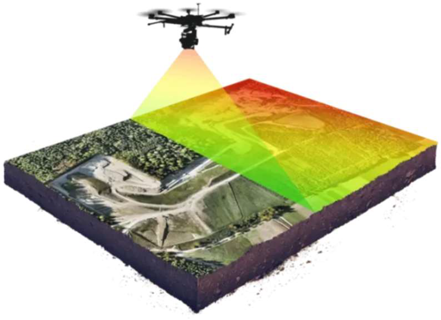
In addition to the software, the hardware is also an important sub-system. In recent years, with the improvement of autonomous driving technology, manufacturers have come up with their own schemes, such as ‘ADS’ from Huawei and ‘FSD’ from Tesla. For drones or the flying cars of the future, these schemes may play an important role in air safety. Take the drones with LiDAR (Light Detection and Ranging) as an example—LiDAR drones (Figure 18) can provide the most accurate and high-resolution 3D models, which may be helpful in dangerous tasks, such as search and rescue after an earthquake. If eVTOL aircraft are equipped with an AI chip, this may realize their full self-flying ability with the help of these sensors.
6. Conclusions
Overall, the controllers designed for the drones in this project are effective. The control system is mainly composed of PID controllers. The PID controllers are the key to the autonomous drone control system.
In future research, artificial intelligence, expert systems, fuzzy control, and neural networks should be applied to further upgrade PID controllers to intelligent PID controllers.
Additionally, with the improvement of AI computer power, eVTOL aircraft could be applied to more areas such as the logistics industry or military action. Autonomous drones with more intelligent control systems will play an essential role in our life soon.
Funding
This research received no external funding.
Institutional Review Board Statement
Not applicable.
Informed Consent Statement
Not applicable.
Data Availability Statement
The raw data supporting the conclusions of this article will be made available by the authors on request.
Conflicts of Interest
The author declares no conflict of interest.
References
- Newcome, L.R. Unmanned Aviation: A Brief History of Unmanned Aerial Vehicles; AIAA: Reston, VA, USA, 2004. [Google Scholar]
- Escobar-Ruiz, A.G.; Lopez-Botello, O.; Reyes-Osorio, L.; Zambrano-Robledo, P.; Amezquita-Brooks, L.; Garcia-Salazar, O. Conceptual Design of an Unmanned Fixed-Wing Aerial Vehicle Based on Alternative Energy. Int. J. Aerosp. Eng. 2019, 2019, 8104927. [Google Scholar] [CrossRef]
- Pang, Q. Design and Smooth Control of a Quadrotor Helicopter, University of Science and Technology of China. 2011. Available online: https://kns.cnki.net/kcms/detail/detail.aspx?dbcode=CMFD&dbname=CMFD2011&filename=1011283775.nh&v=ZlD54mmmGF4LGLpHAE0VvtpFINu0rQoGOlIJBjVvNqXRqDGpNx%mmd2BZBadKLnYevH1x (accessed on 13 March 2021).
- Su, J.; Fan, P.; Cai, K. Attitude Control of Quadrotor Aircraft via Nonlinear PID. J. Beijing Univ. Aeronaut. Astronaut. 2011, 37, 9. [Google Scholar]
- Jiang, F.; Li, L.; Cao, B. DC Motor Control with Improved Linear PID Algorithm. Electr. World 2021, 2, P92–P94. [Google Scholar]
- CSDN Forum. Simulink Simulation and PD Cascade Control Trajectory Tracking Simulation of Four-Rotor Aircraft. 2020. Available online: https://download.csdn.net/download/weixin_43145941/13712261 (accessed on 13 March 2021).
- Gao, Q.; Yuan, L.; Wu, Q. Attitude control of a quadrotor UAV based on new LQR. Manuf. Autom. 2014, 37, 13–15. [Google Scholar]
- Hajiyev, C.; Vural, S.V. LQR Controller with Kalman Estimator Applied to UAV Longitudinal Dynamics. Sci. Res. 2012, 4, P36–P41. Available online: https://m.scirp.org/papers/28381 (accessed on 11 March 2021). [CrossRef]
- Wintra. LiDAR Drone. Flyability, 2024. Available online: https://www.flyability.com/hs-fs/hubfs/lidar-drone-flyability-2.jpg?width=1440&height=954&name=lidar-drone-flyability-2.jpg (accessed on 31 July 2024).
Figure 1.
Three-dimensional models.
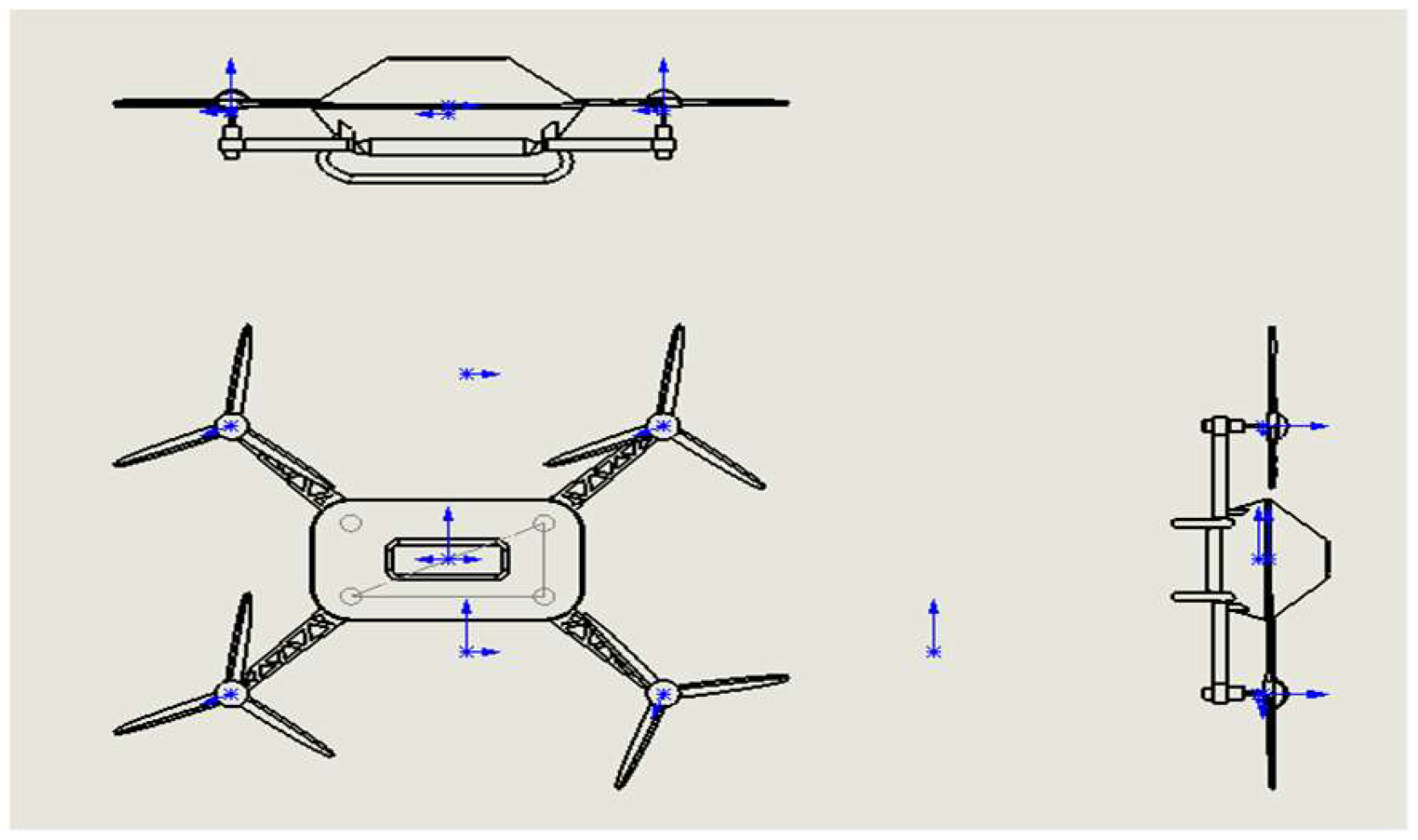
Figure 2.
Flow chart.
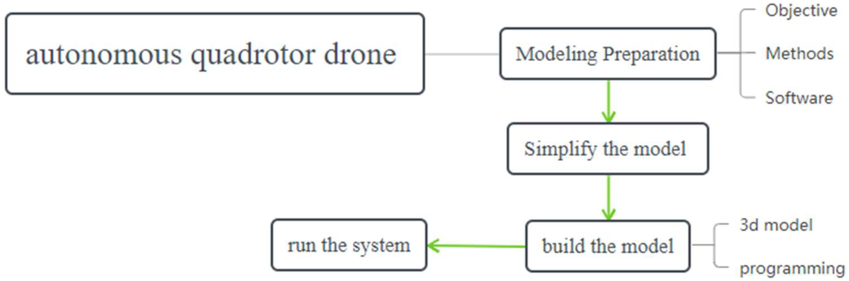
Figure 3.
Basic Structure of Drone.
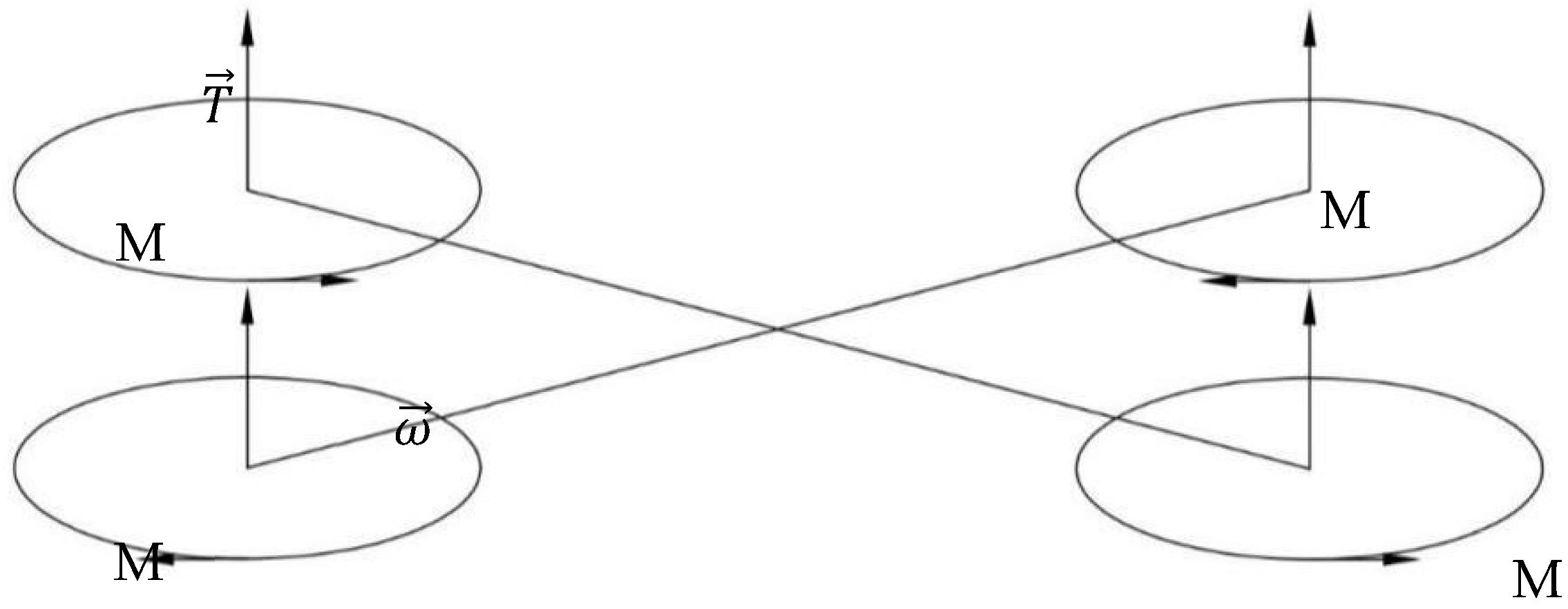
Figure 4.
Structure.
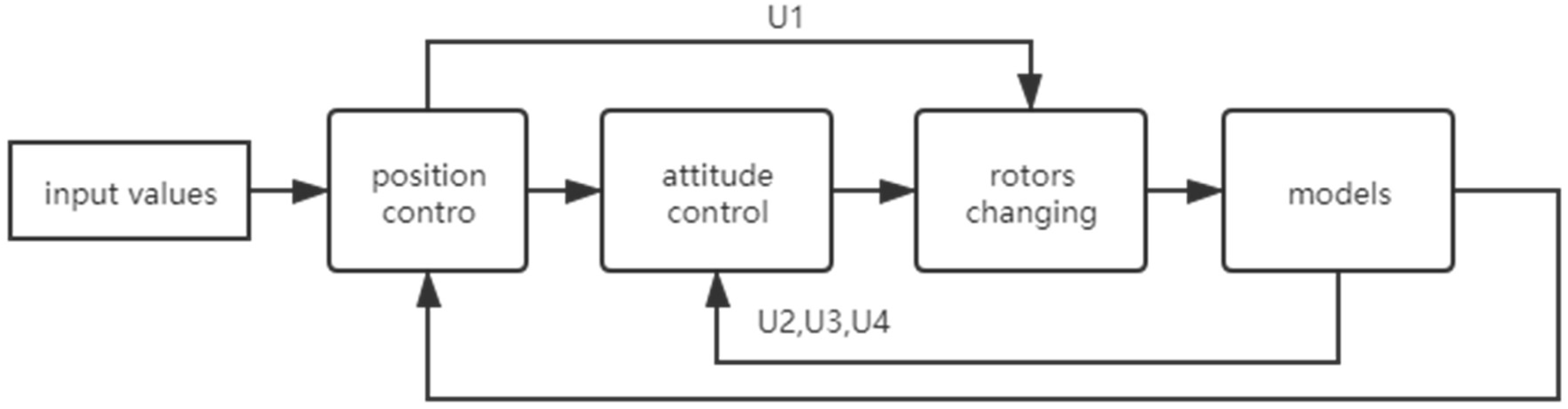
Figure 5.
The controller in the initial stage.
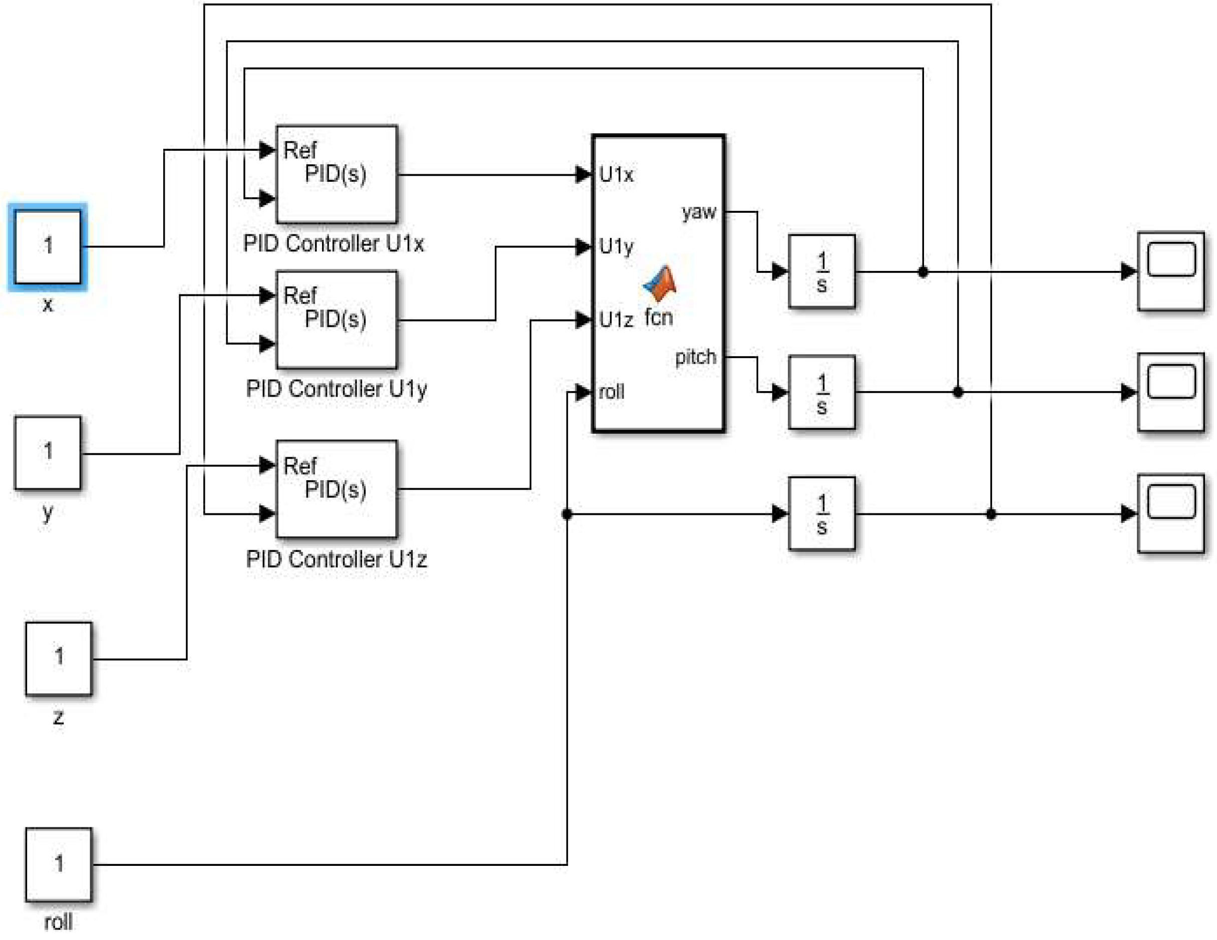
Figure 6.
The parameters of the drone. [Source: https://www.flyeval.com/ (accessed on 20 March 2021)].
Figure 6.
The parameters of the drone. [Source: https://www.flyeval.com/ (accessed on 20 March 2021)].
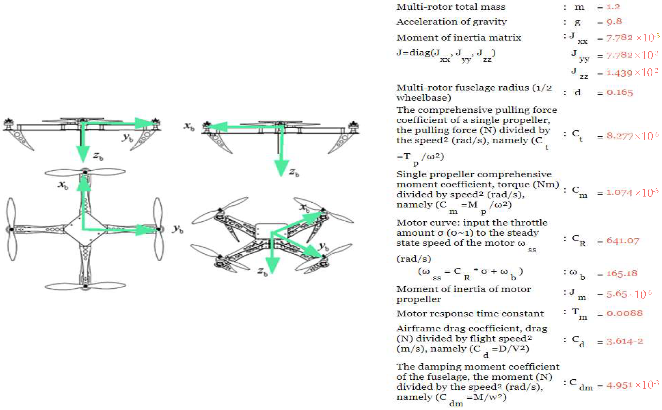
Figure 7.
The details given to the drone. [Source: https://www.flyeval.com/ (accessed on 20 March 2021)].
Figure 7.
The details given to the drone. [Source: https://www.flyeval.com/ (accessed on 20 March 2021)].
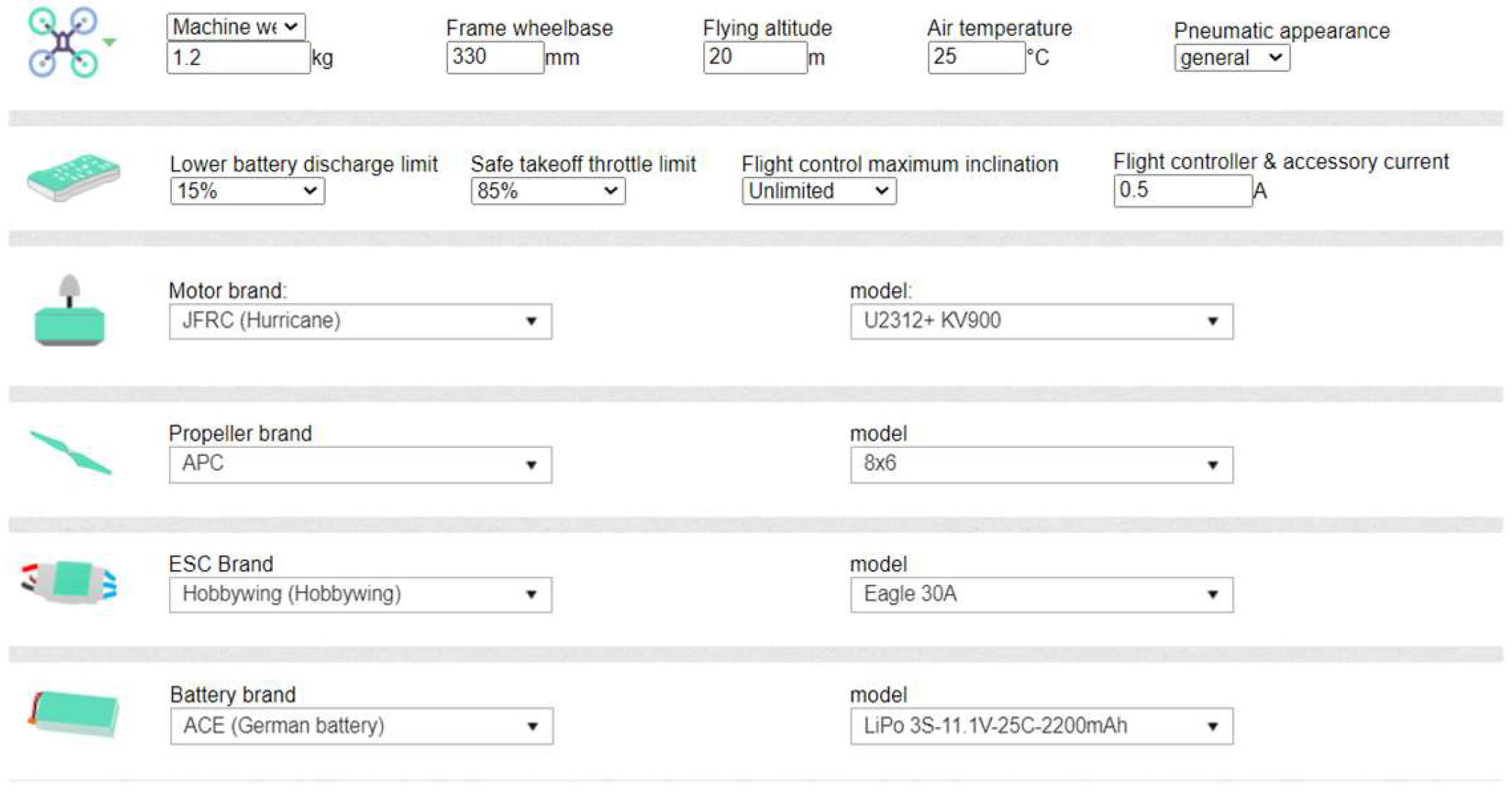
Figure 8.
Part of the second order [6].
Figure 8.
Part of the second order [6].
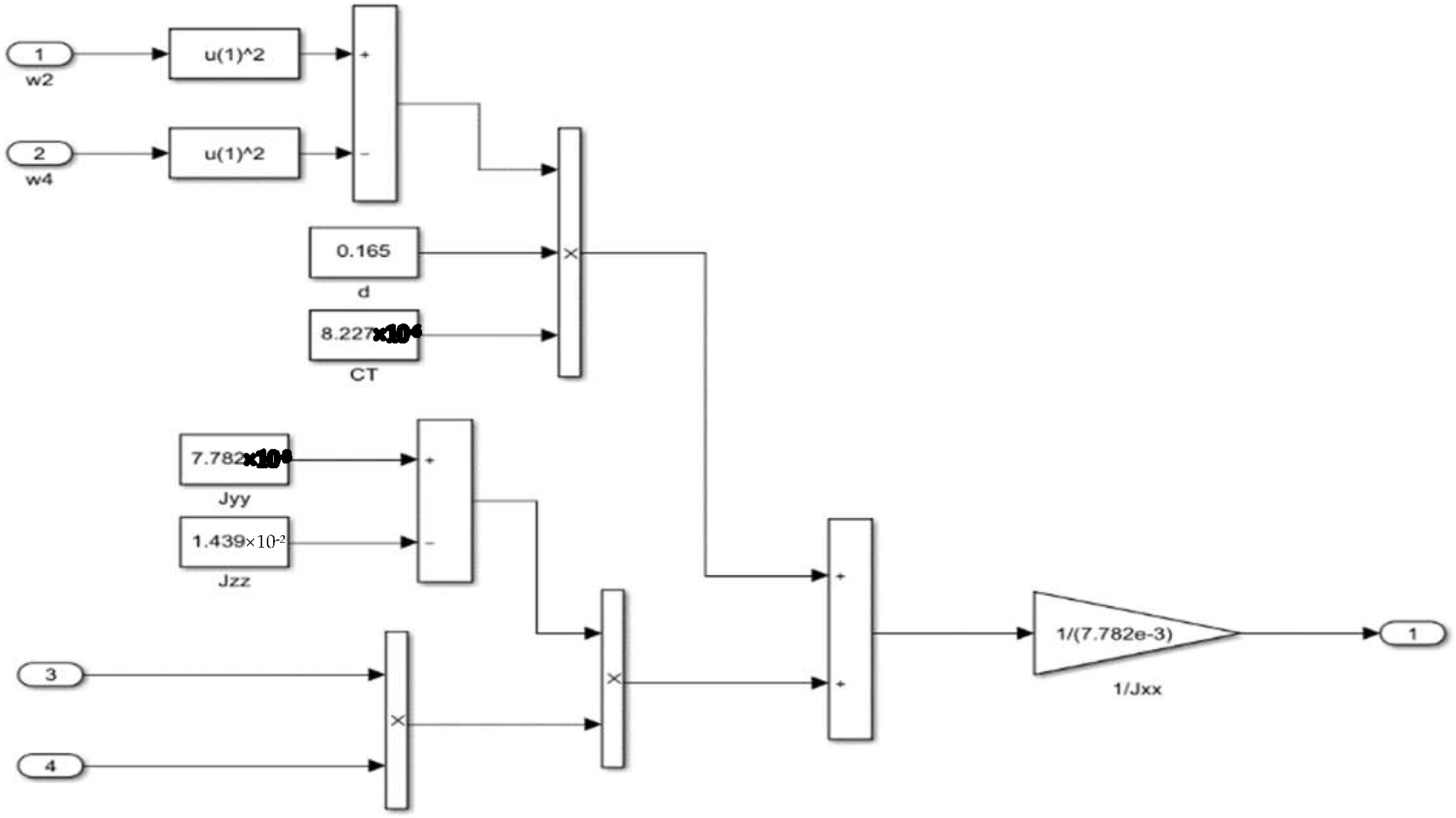
Figure 9.
The PD controller [6].
Figure 9.
The PD controller [6].
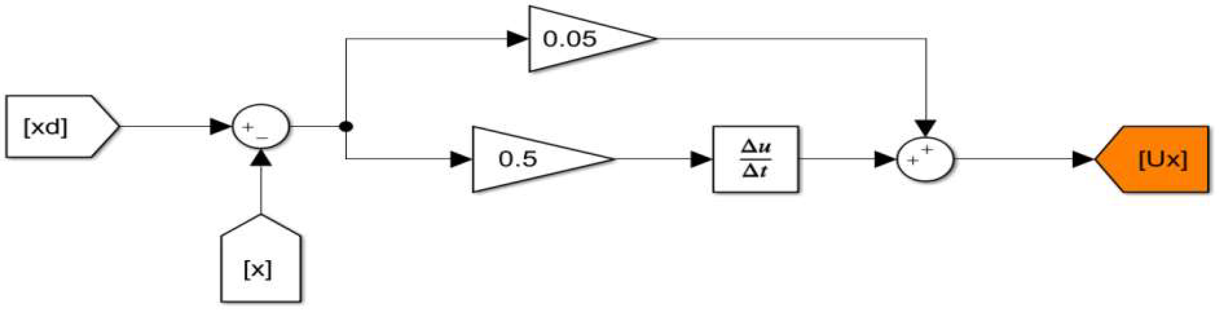
Figure 10.
The code for the position controller [6].
Figure 10.
The code for the position controller [6].
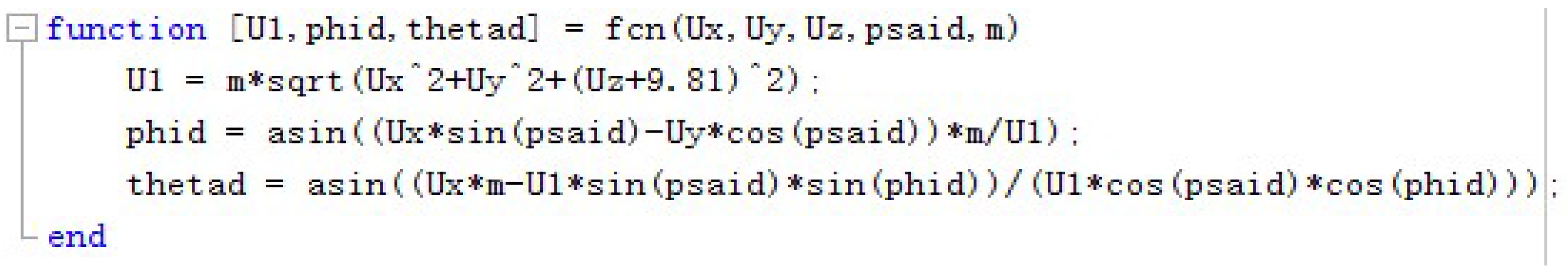
Figure 11.
The code for the rotors [6].
Figure 11.
The code for the rotors [6].
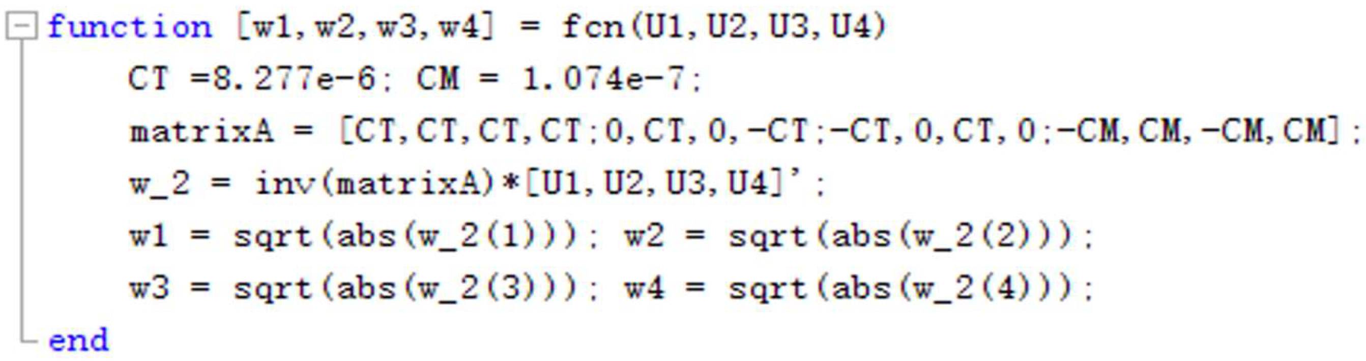
Figure 12.
The code for the Euler angles [6].
Figure 12.
The code for the Euler angles [6].
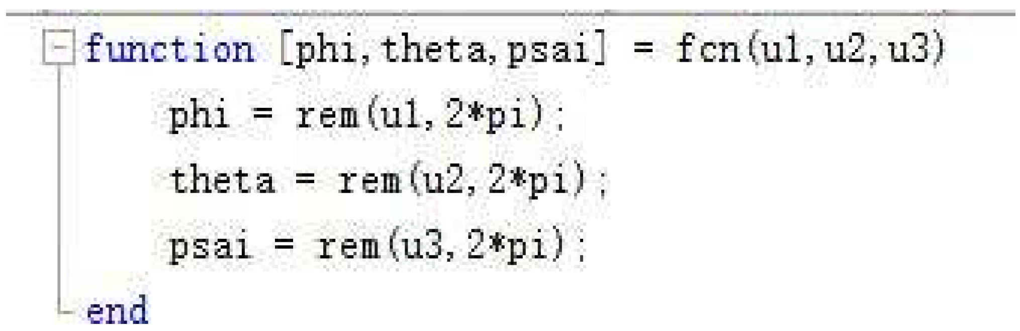
Figure 13.
Change in attitude angles with time.
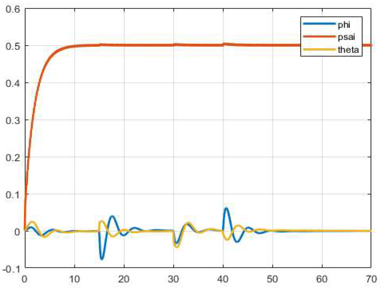
Figure 14.
Expected position and actual position.
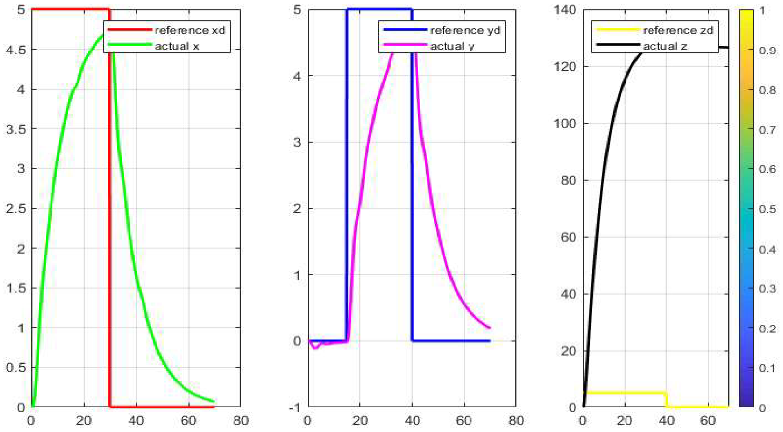
Figure 15.
Motion trail.
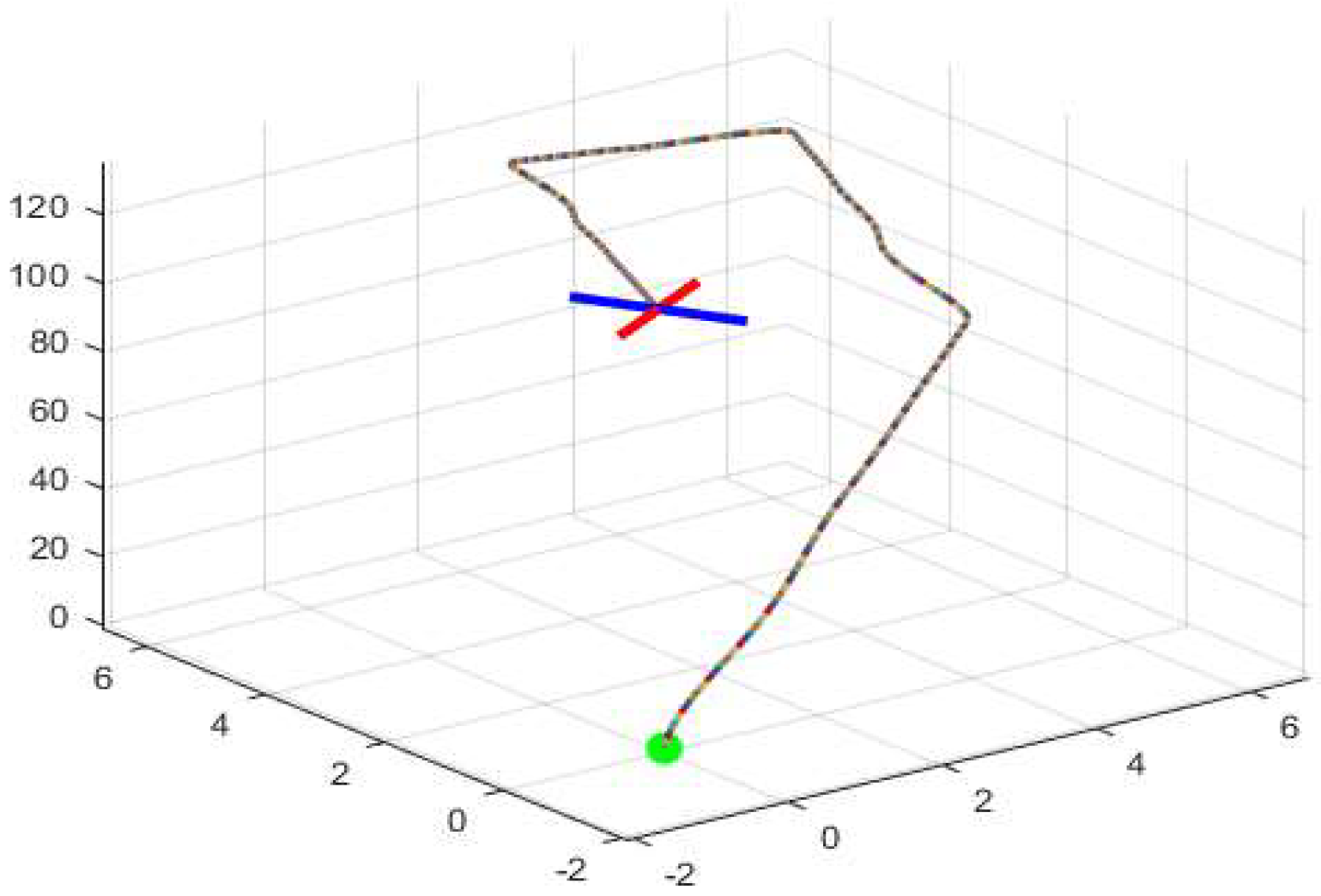
Figure 16.
The block diagram for the LQR [7].
Figure 16.
The block diagram for the LQR [7].
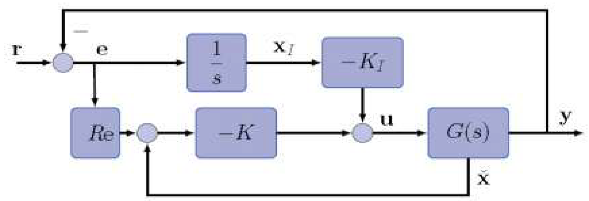
Figure 17.
The comparison from [7].
Figure 17.
The comparison from [7].
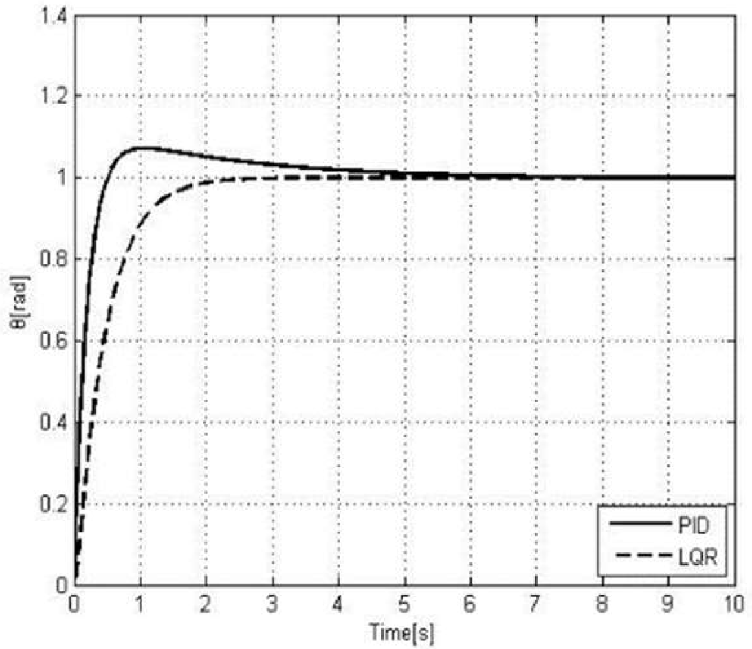
Figure 18.
LiDAR drone [9].
Figure 18.
LiDAR drone [9].
Disclaimer/Publisher’s Note: The statements, opinions and data contained in all publications are solely those of the individual author(s) and contributor(s) and not of MDPI and/or the editor(s). MDPI and/or the editor(s) disclaim responsibility for any injury to people or property resulting from any ideas, methods, instructions or products referred to in the content. |
© 2025 by the author. Licensee MDPI, Basel, Switzerland. This article is an open access article distributed under the terms and conditions of the Creative Commons Attribution (CC BY) license (https://creativecommons.org/licenses/by/4.0/).
Share and Cite
MDPI and ACS Style
Yu, W. Design of an Autonomous Drone. Eng. Proc. 2024, 80, 12. https://doi.org/10.3390/engproc2024080012
AMA Style
Yu W. Design of an Autonomous Drone. Engineering Proceedings. 2024; 80(1):12. https://doi.org/10.3390/engproc2024080012
Chicago/Turabian StyleYu, Wendi. 2024. "Design of an Autonomous Drone" Engineering Proceedings 80, no. 1: 12. https://doi.org/10.3390/engproc2024080012
APA StyleYu, W. (2024). Design of an Autonomous Drone. Engineering Proceedings, 80(1), 12. https://doi.org/10.3390/engproc2024080012