Proceeding Paper

Numerical Approach to Fatigue Life Prediction of Harrow Tines Considering Geometrical Variations †

by
Arafater Rahman
and
Mohammad Abu Hasan Khondoker
*
Industrial System Engineering, University of Regina, 3737 Wascana Pkwy, Regina, SK S4S0A2, Canada
*
Author to whom correspondence should be addressed.
Presented at the 1st International Conference on Industrial, Manufacturing, and Process Engineering (ICIMP-2024), Regina, Canada, 27–29 June 2024.
Eng. Proc. 2024, 76(1), 75; https://doi.org/10.3390/engproc2024076075
Published: 8 November 2024

Abstract

Harrow tine is a widely used tool for mechanical weeding. However, the effect of its geometry on its fatigue life is something that has not been studied well yet. In this work, two different harrow tines (0.5260” HT and 0.6253” HT) were analyzed to understand how their geometry affects their fatigue life under different field conditions and material properties. Finite element analyses were performed on these harrow tines by applying different degrees of leg deflections (3, 6, 8, 10, and 12 inches) for von Mises stress distributions and failure life cycles. The results suggested that 0.526” HT has a longer cycle life than 0.6253” HT. With the largest leg deflection and controlled conditions, 0.5260” HT exhibits a harrowing capability of 133.62 hectares, which is larger than 0.6253” HT’s 117.66 hectares. Apart from the numerical analyses, prototypes (1:0.35 scaled-down model) of these harrow tines were additively manufactured using a rigid ultraviolet curable resin. Finally, a custom test setup was used to perform simple load-bearing tests of these harrow tines.

1. Introduction

Saskatchewan is often known as the agricultural hub of Canada through its gigantic production of seeds and grains, including canola, wheat, pulses, barley, oilseeds, etc. It became the world’s largest producer of field crops such as canola and oats, as well as a cereal exporter, due to its expansive terrain, level topography, and fertile arable land, rendering it a prime location for cultivating field crops [1]. To maintain this consistent production of field crops, weed management considering effective controlling mechanisms, time sensitivity, and cost-effectiveness becomes crucial. There are many accustomed weed management systems, such as mechanical, chemical, biological, and manual systems [2,3,4,5]. The mechanical weed control approach offers a significant resolution to frequent weed disruption without any waiting period. Even this waiting period might lead to a devastating crop production rate if weeds encounter herbicide resistance. Nevertheless, mechanical tillage practices gained popularity for inter-row weed management due to having target erosion efficiency, quick effectivity, and cost-effectiveness [6,7]. Manual harrowing loses its appeal because of having labor-intensive work [8,9], whereas mechanical harrowing offers precision in weed disruption and is even more economical [10,11]. Canadian farmers with relatively large agricultural fields in the prairie regions have recently adopted mechanical harrowing as the only viable and reasonable technique before seeding. However, the unexpected failure of harrow tines during their usage significantly affects farmers during the very short harrowing season [12]. During tillage, heavy vibration is generated from the field, which leads to failure of the harrow tines. Therefore, a life cycle assessment of harrow tines is crucial to predict their failure [13]. This research aims to predict commercially available harrow tine’s life through finite element analysis, allowing farmers to plan replacement to avoid unexpected stoppage of the harrowing process. Hence, two different harrow tines (namely, 0.62530” HT and 0.526” HT) were analyzed under identical sets of deflections that might occur on the field considering different field conditions, and a comparative analysis was used to distinguish their performance under the same deflections considering their geometrical variations. Apart from the numerical aspect, the additively manufactured prototype harrow tines were tested to validate the failure results observed in the numerical model.

2. Materials and Design

The harrow tines named 0.526” HT and 0.62530” HT (shown in Figure A1a,b) were made of ASTM A229 [14], a class 1 oil-tempered wire, listed in Table 1 [15]. These harrow tine models were chosen to study the effect of their geometrical variations on their performance. Because of the bending deformation of the harrow tines near the coil turns, they were modeled as helical coil torsion springs [16]. This assumption is further supported by the fact that the torsion spring can absorb as well as release energy [17] during mechanical tillage and provide torque, which effectively leads to soil penetration.

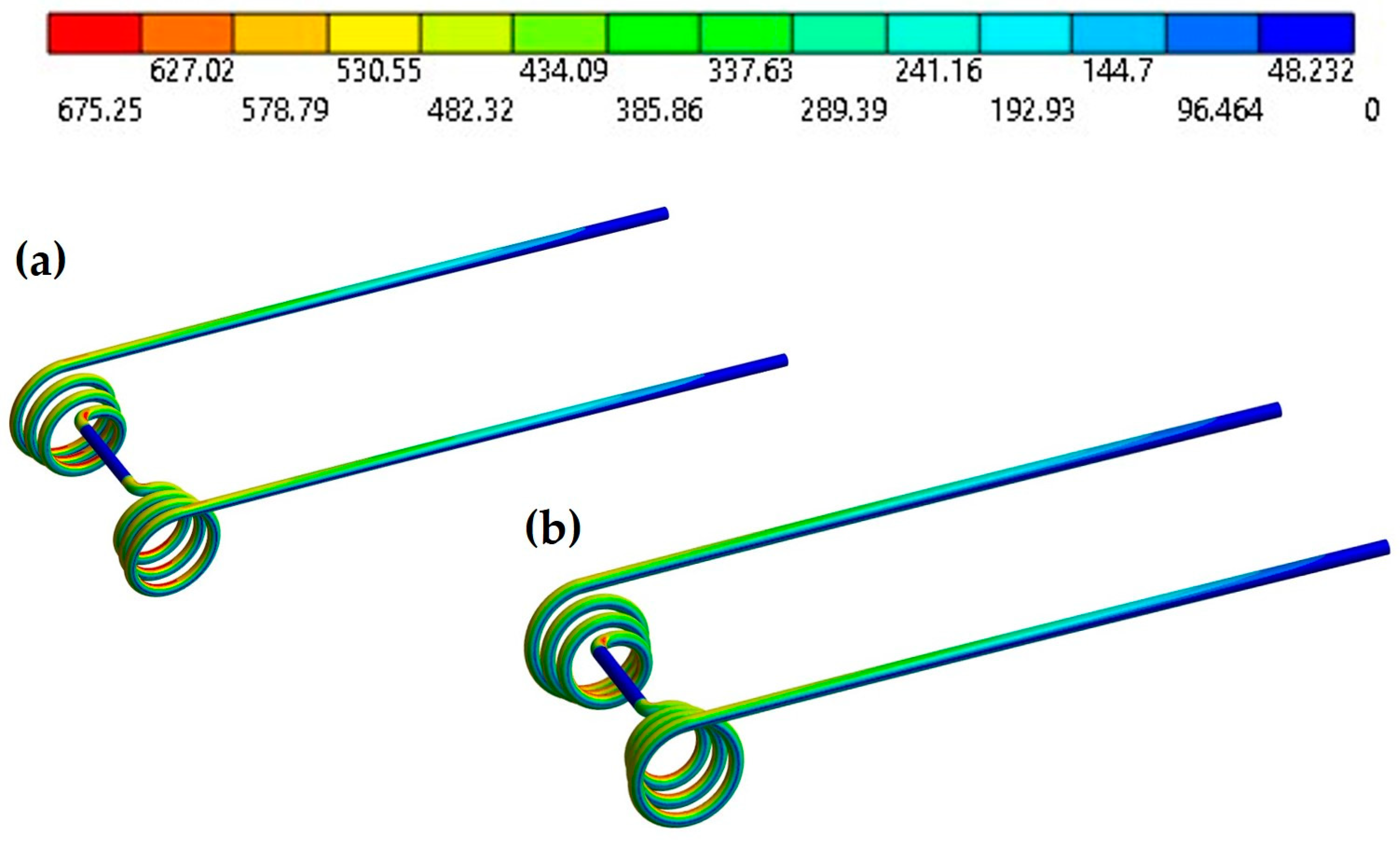
3. Numerical Analysis and Rapid Prototyping

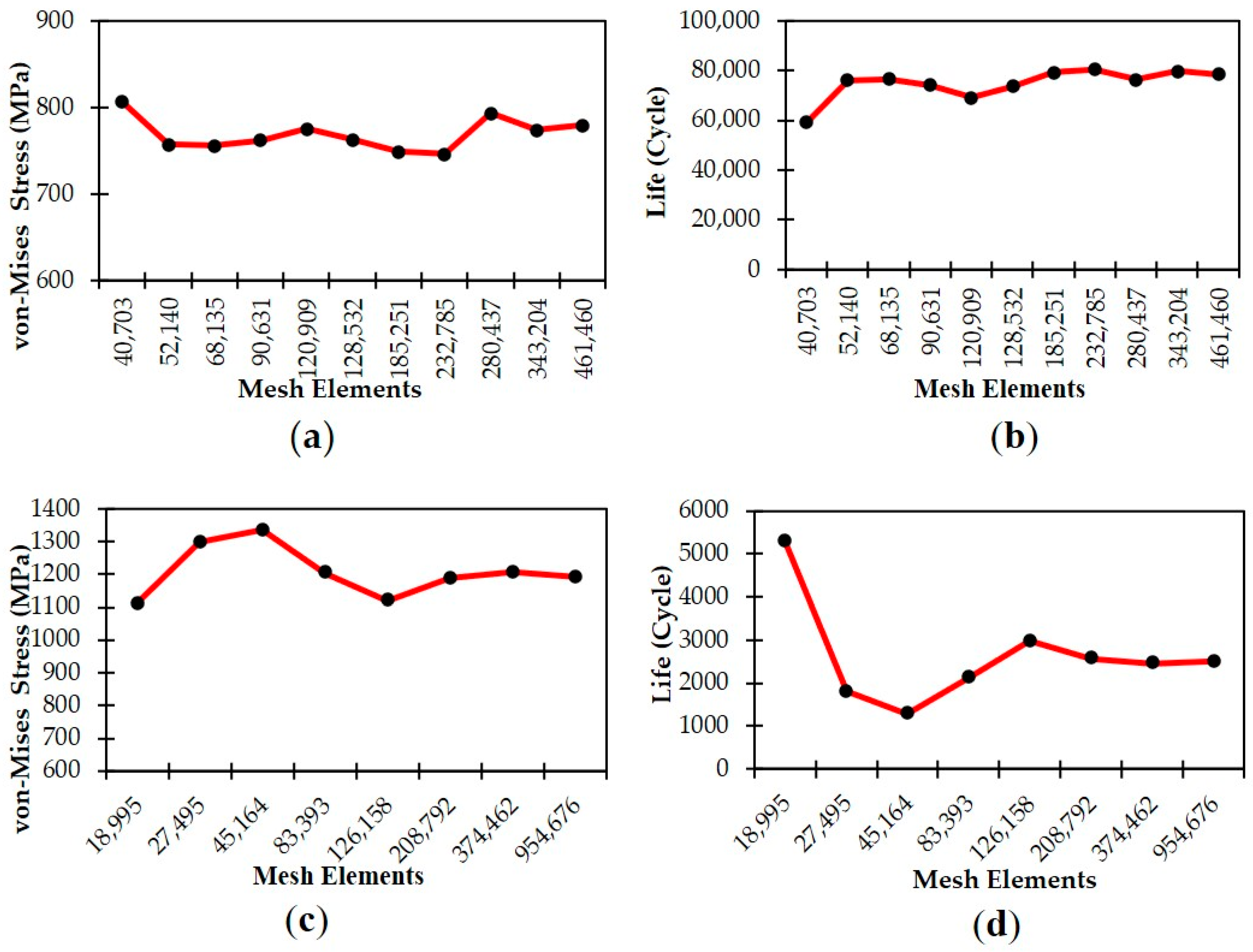
3.1. Mesh Convergence

First, both harrow tines were subjected to mesh dependency tests to establish the mesh-independent bodies against the mesh element sizes. In continuum damage mechanics (CMD), mesh refinement does not always ensure accuracy as extreme refinement can cause spurious mesh sensitivity, which has a severe impact on predictions [18]. Figure 1 shows mesh-dependency plots of both harrow tines for both von Mises stress and life. In the mesh-dependency test with the skewness metric, the 0.62530” HT model converged at a 3.2 mm mesh size, resulting in 182,020 elements, whereas the 0.5260” HT model converged at a 3 mm mesh size, counting a total of 208,792 elements. The skewness mesh metric average was 0.4328–0.4569, which is close to the recommended guide [19] to rectify the mesh independence model’s accuracy.

3.2. Fatigue Life Framework

The ANSYS fatigue tool for life prediction was utilized for both the 0.526” HT and 0.62530” HT models. To estimate the theoretical stress–life (S-N) curve, Basquin empirical Equation (1) for bending load approximation was used. Figure A1c,d show two S-N curves for 0.526” HT and 0.62530” HT [20,21] respectively.
S f = a × ( N f ) b
where S f = stress amplitude, N f = number of cycles, and a and b are both constants [20]. Again, SN-None means stress correction theory was considered where a fully reversed loading approach was utilized. In the finite element model, the staple, a straight wire between the coil turns on both sides, was constrained to be fixed as happens in actual field conditions. Then, different degrees of leg deflections (3, 6, 8, 10, and 12 inches) were applied at the end of their legs, resembling deformation that occurs due to reaction forces from different soil conditions during harrowing.

3.3. 3D Printing Approach

A rapid prototyping approach was considered to perform a comparative analysis of failure phenomena for both harrow tines. A resin-based liquid crystal display (LCD) 3D printer (Make: ELEGOO; Model: Jupiter 6K, Shenzhen, China) was used to 3D-print prototypes of the harrow tines in their 35% scale. To ensure the legs were not distorted during printing and post-curing, connecting struts were added to the 3D model before printing. After printing, these struts were removed when removing support structures manually.

4. Results

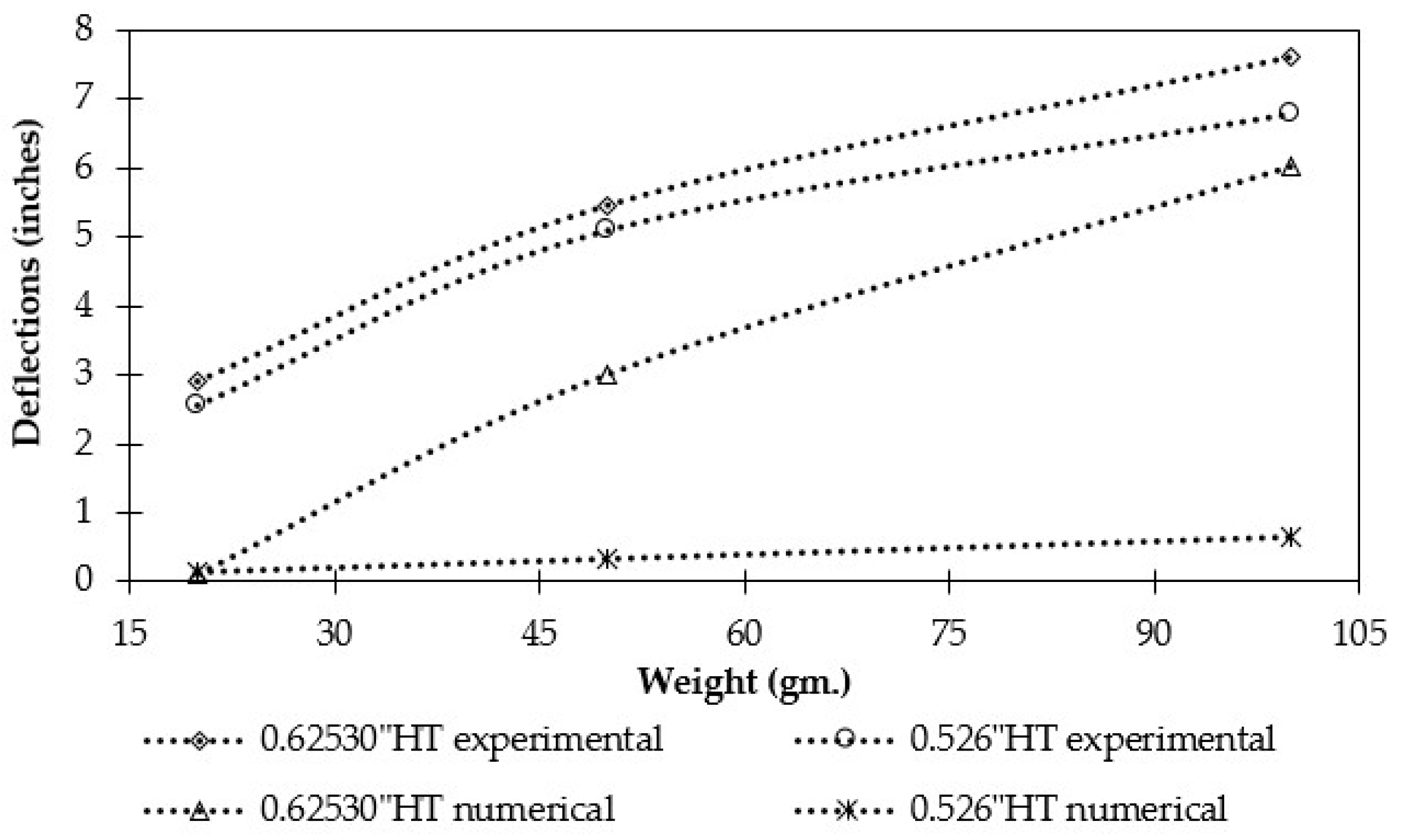
4.1. Fatigue Life Expectancy Against Different Deflections

Figure 2 and Figure 3 show the contour of von Mises stresses and life cycle for both 0.526” HT and 0.62530” HT, respectively under 12 inches of deflections. When the 0.526” HT is deflected 12 inches, the maximum von Mises stress is found to be 667.23 MPa (Figure 2a). Again, the maximum stress for 0.62530” HT is slightly higher, 675.25 MPa (Figure 2b). A common phenomenon observed for both models is the location of maximum stress that is near the inner coils. Additionally, this higher-order deformation significantly lowers the fatigue life for both harrow tines, as shown in Table 2.
The results revealed that, for all degrees of deformations, 0.62530” HT experienced higher stresses than 0.526” HT. There might be several reasons that distinguish the stress discrepancy between the two models, but two factors, such as geometrical variations and material properties, are more pertinent for comparative analysis. Appropriate wire diameter selection is crucial for harrow tine as ASTM A229-derived material properties are wire-specific. To an extent, the correlation between the spring rate and wire diameter is a pivotal determinant in comprehending the mechanical characteristics of springs, as shown in Equation (2) [21]
k = d 4 E 64 DN a
where k = spring rate of torsional spring, d = wire diameter, D = coil’s inner dia., N a = number of active coils, and E = shear modulus [21]. Though the effect of the wire diameter has no significance on the closed coil spring’s rate [22], the equational relation reveals that the influence of the wire diameter on the torsional spring rate is proportional. But Equation (2) is not straightforward for conical helical torsion springs used in harrow tines. Some other factors, such as pitch, spring free length, coil inner diameter, and pitch angle, overshadow the preferential effect of wire diameter. For instance, the number of active coils is determined by the axial pitch and effective spring height [23]. Conical helical springs demonstrated a higher load-bearing ability than conventional-designed helical springs for the same dimensions [24]. In this regard, 0.62530” HT and 0.526” HT are both made with double conical helical torsion springs, but their wire diameter, pitch, pitch angle, coil height, and coil inner diameter variations make their performance characteristics different. Nazir et al. [24] showed that helical springs offer the highest load-carrying capability with a higher wire diameter and lower pitch combination. However, anything beyond the optimal wire diameter accelerates energy loss, which affects the spring fatigue life. Consequently, a small coil height and wire diameter can improve the wear resistance of helical springs significantly. On the contrary, a large inner coil diameter contributes to wear resistance improvement, which is not as significant as a small coil height and small wire diameter [25]. For example, 0.62530” HT made with 0.625 inches of wire has an outer coil diameter of 4.5 inches and an inner coil diameter of 2.625 inches, maintaining 0.927 constant pitch, whereas 0.5 inches of wire made 0.526” HT offers 3.75 inches and 2.625 inches of outer and inner coil, respectively, following 0.77 pitch. As we know, a higher wire diameter offers higher stiffness for the helical torsion springs, so 0.62530” HT is supposed to provide a higher fatigue life experienced with lower stress. But for every deflection, 0.62530” HT showed a lower fatigue life compared with the 0.526” HT model. For instance, 0.526” HT showed better fatigue life than 0.62530” HT, even in 12-inch deflections, as shown in Figure 3a,b, respectively. This is because of the pitch, wire diameter, and coil height influences we discussed earlier. Though both models have three symmetrical coils, 0.526” HT’s coils seemed to be more compact to offer more active coil surfaces considering a small pitch angle of 13.67°. The coil height difference between the two models is not significant to compare. Again, 0.62530” HT offers 0.927 constant pitch between coils, which is higher compared with 0.77 from 0.526” HT.
The primary goal of this research is to make fatigue life predictions, and by utilizing this information, farmers can save time. FEM-derived prediction converting to farmers’ convenience is also essential. Hence, the average speed of harrowing vehicles in Saskatchewan is 8–12 km/h [26], where optimal harrowing capacity is observed at 16.66 ha/h after testing on cultivated wheat stubble, summer fallow, cultivated barley stubble, and cultivated rapeseed stubble [27]. Harrows respecting different deflections that might occur are shown in Table 2. The 0.526” HT model offers a more reliable fatigue life in the context of 3660.62-hectare field harrowing against repetitive 6-inch deflections for 219.725 h, whereas the 0.62530” HT sustains up to 193.694 h featuring 3226.94 hectares of harrowing operation. Both models showed poor performance considering 133.62 hectares and 117.66 hectares against 12-inch deflections, but these huge deflections from the field are uncertain. Consequently, we calculated how long our simulated harrow tines can be sustained in a real field, offering extraordinary performance on 3-inch deflections, which the ANSYS fatigue tool failed to estimate after 106 cycles. Therefore, here, both enlisted models can sustain more than 4627.27 hectares of harrowing, whereas the 0.526” HT is supposed to be superior.

4.2. Comparative Analysis of Prototype Models

The 0.526” HT and 0.62530” HT prototype models underwent a load-bearing approach where deflections were measured for an identical load set (20, 50, and 100 gm). This experimental analysis was carried out for a comparative analysis between the models and to validate their performance characteristics under different deflections, as summarized in Table 2. A bracket system was fabricated where the harrow tine’s staple was fixed through screwing from both ends. Both side tightening schemes impede the staple’s distortion while applying the load on the legs, as represented in Figure 4a–h. Different dead weights were hung on the leg, and we measured the harrow tine deflections. Loads were consistently applied at a 1 mm distance from the leg end for all observations. The 0.62530” HT showed higher deflections for all weight loads compared with the 0.526” HT, which exhibited lower deflections. The same observation was examined in the FEM approach, maintaining the experimental framework. A similar trend is observed in the numerically derived results, as 0.526” HT exhibits higher stiffness against the definite loads shown in Figure 5. The effects of pitch, wire diameter, pitch angle, and coil height were analyzed in the previous section, which could influence the harrow tine stiffness.
Again, larger legs from the 0.62530” HT model can increase the deflections more than the 0.526” HT, but springs made with large wire diameters generally show greater deflections, as observed in other research works [28,29]. For numerical validation, epoxy resin was selected for 35% of the prototype models instead of the material used in 3D printing. This is reflected in the deflection curves, where the numerical deflection curves showed lower values in all cases. This is because the required material property of the actual resin was missing. However, the results are still valid for comparative analysis and show actual trends that are similar from an experimental perspective.

5. Conclusions

Two different harrow tines underwent definite deflection sets, and their response against each deflection was determined through the FEM. A comparative study based on numerical results was carried out in which 0.526” HT harrow tine showed better reliability compared with 0.62530” HT. Though 0.62530” HT was designed with higher-order ASTM A229 wire and has long-length legs, 0.526” HT exhibited better sustainability in every aspect. A wire diameter over the optimal range causes a detrimental impact on harrow tine performance. Moreover, the pitch, coil height, coil inner diameter, and pitch angle are crucial for helical torsion spring design, which has a reflection in harrow tine performance. For instance, a greater wire diameter influences greater wear during cyclic fatigue tests. Even a higher pitch angle and higher pitch have direct adverse effects on the spring rate. These parameters contribute to the 0.62530” HT’s lower fatigue life despite having a larger wire diameter. Consequently, 0.62530” HT showed 117.66 ha/h harrowing ability under 12 inches deflection, whereas 0.526” HT showed 133.62 ha/h following the same observations. Additionally, higher leg length might have a positive aspect on loner fatigue life achievement, but the optimum pitch angle, pitch, and wire diameter overshadow the impact of large length. Eventually, additive manufacturing was utilized to fabricate a harrow tine model for numerical analysis validation. Experimental load-bearing results verify the reliability of 0.526” HT over 0.62530” HT through lower deflections offered under the same weights. Nevertheless, again, the FEM approach has taken a 35% scale prototype model into account to prove the displacement phenomena that occur in experimental load-bearing tests.

Author Contributions

"Conceptualization, A.R. and M.A.H.K.; Methodology, A.R.; Software, A.R.; Validation, A.R. and M.A.H.K.; Formal Analysis, A.R.; Investigation, A.R.; Resources, M.A.H.K.; Data Curation, A.R.; Writing—Original Draft Preparation, A.R.; Writing—Review & Editing, M.A.H.K.; Visualization, A.R.; Supervision, M.A.H.K.; Project Administration, M.A.H.K. and A.R.; Funding Acquisition, M.A.H.K. All authors have read and agreed to the published version of the manuscript.

Funding

This research is supported by the Natural Sciences and Engineering Research Council of Canada.

Institutional Review Board Statement

Not applicable.

Informed Consent Statement

Not applicable.

Data Availability Statement

All data is posted in the manuscript. For any further queries, please contact the corresponding author (mohammad.khondoker@uregina.ca).

Conflicts of Interest

The author declares no competing interests.

Appendix A

Figure A1. (a) Engineering drawing of 0.526” HT; (b) engineering drawing of 0.62530” HT; (c) SN curve of 0.526” HT; (d) SN curve of 0.62530” HT.
Engproc 76 00075 g0a1

References

  1. Pierre, M.S.; Mhlanga, S. Saskatchewan Continues to Live up to the Title of Breadbasket of Canada Canadian Agriculture at a Glance. Available online: https://www150.statcan.gc.ca/n1/pub/96-325-x/2021001/article/00008-eng.htm (accessed on 18 March 2024).
  2. Zeng, Z.; Martin, A.; Chen, Y.; Ma, X. Weeding Performance of a Spring-Tine Harrow as Affected by Timing and Operational Parameters. Weed Sci. 2021, 69, 247–256. [Google Scholar] [CrossRef]
  3. Pradel, M.; de Fays, M.; Seguineau, C. Comparative Life Cycle Assessment of Intra-Row and Inter-Row Weeding Practices Using Autonomous Robot Systems in French Vineyards. Sci. Total Environ. 2022, 838, 156441. [Google Scholar] [CrossRef] [PubMed]
  4. Chandel, N.S.; Chandel, A.K.; Roul, A.K.; Solanke, K.R.; Mehta, C.R. An Integrated Inter- and Intra-Row Weeding System for Row Crops. Crop Prot. 2021, 145, 105642. [Google Scholar] [CrossRef]
  5. Melander, B.; Liebman, M.; Davis, A.S.; Gallandt, E.R.; Bàrberi, P.; Moonen, A.C.; Rasmussen, J.; van der Weide, R.; Vidotto, F. Non-Chemical Weed Management. In Weed Research: Expanding Horizons; Wiley: Hoboken, NJ, USA, 2017; pp. 245–270. ISBN 9781119380702. [Google Scholar]
  6. Adigun, J.A.; Adeyemi, O.R.; Daramola, O.S.; Olorunmaiye, P.M. Response of Cowpea ( Vigna Unguiculata, L., Walp) to Inter-Row Spacing and Weed Competition. Agric. Trop. Et. Subtrop. 2020, 53, 73–79. [Google Scholar] [CrossRef]
  7. Alba, O.S.; Syrovy, L.D.; Duddu, H.S.N.; Shirtliffe, S.J. Increased Seeding Rate and Multiple Methods of Mechanical Weed Control Reduce Weed Biomass in a Poorly Competitive Organic Crop. Field Crops Res. 2020, 245, 107648. [Google Scholar] [CrossRef]
  8. Robinson, T.; Sussell, A.; Scott, K.; Poplin, G. Health Conditions among Male Workers in Mining and Other Industries Reliant on Manual Labor Occupations: National Health Interview Survey, 2007–2018. Am. J. Ind. Med. 2023, 66, 692–704. [Google Scholar] [CrossRef] [PubMed]
  9. Van Der Weide, R.Y.; Bleeker, P.O.; Achten, V.T.J.M.; Lotz, L.A.P.; Fogelberg, F.; Melander, B. Innovation in Mechanical Weed Control in Crop Rows. Weed Res. 2008, 48, 215–224. [Google Scholar] [CrossRef]
  10. Spaeth, M.; Schumacher, M.; Gerhards, R. Comparing Sensor-Based Adjustment of Weed Harrowing Intensity with Conventional Harrowing under Heterogeneous Field Conditions. Agronomy 2021, 11, 1605. [Google Scholar] [CrossRef]
  11. Tataridas, A.; Kanatas, P.; Chatzigeorgiou, A.; Zannopoulos, S.; Travlos, I. Sustainable Crop and Weed Management in the Era of the EU Green Deal: A Survival Guide. Agronomy 2022, 12, 589. [Google Scholar] [CrossRef]
  12. Tony Seskus. Farmers Seeking “right to Repair” Rules to Fix Their Own Tractors Gain White House Ally. CBC 2021. Available online: https://www.cbc.ca/news/business/biden-farmers-right-to-repair-1.6105394 (accessed on 8 February 2024).
  13. Pinke, G.; Giczi, Z.; Vona, V.; Dunai, É.; Vámos, O.; Kulmány, I.; Koltai, G.; Varga, Z.; Kalocsai, R.; Botta-dukát, Z.; et al. Weed Composition in Hungarian Phacelia (Phacelia Tanacetifolia Benth.) Seed Production: Could Tine Harrow Take Over Chemical Management? Agronomy 2022, 12, 891. [Google Scholar] [CrossRef]
  14. ASTM A229; Standard Specification for Steel Wire, Quenched and Tempered for Mechanical Springs. ASTM International: West Conshohocken, PA, USA, 2024.
  15. MatWeb Material Property Data. Available online: https://www.matweb.com/search/datasheet.aspx?matguid=417e182b8e9c42e7b84e437ee233908d&ckck=1 (accessed on 8 February 2024).
  16. Šarić, I.; Čolić, M.; Muratović, E.; Delić, M.; Muminović, A.J. Design and Development of Compression and Torsion Springs Using CAD/CAE. In Advanced Technologies, Systems, and Applications VI: Proceedings of the International Symposium on Innovative and Interdisciplinary Applications of Advanced Technologies (IAT) 2021; Springer: Cham, Switzerland, 2022; pp. 635–644. [Google Scholar]
  17. Böğrekci, İ.; Demircioğlu, P.; Ozer, G. Design and analysis of cost-effective compact disc harrow. Int. J. 3D Print. Technol. Digit. Ind. 2022, 6, 228–235. [Google Scholar] [CrossRef]
  18. Do, M.-H.; Nguyen, V.-T.; Omnes, P. Analysis of Dissipation Operators That Damp Spurious Modes While Maintaining Discrete Approximate Geostrophic Equilibriums for the B-Grid Staggered Scheme on Triangular Meshes. J. Comput. Phys. 2023, 489, 112261. [Google Scholar] [CrossRef]
  19. Ansys, R. ANSYS Mechanical APDL, Product Release 13.0; ANSYS Inc.: Canonsburg, PA, USA, 2012. [Google Scholar]
  20. Budynas, R.G.; Nisbett, J.K.; Tangcchaichit, K.; Shigley, J.E. Shigley’s Mechanical Engineering Design, 11th ed.; McGraw Hill Education: New York, NY, USA, 2021. [Google Scholar]
  21. Hasan, H.M.; Razzaq, H.Y.; Saleh, I.R. Machine Elements and Design Fundamental. In Proceedings of the Sixth International Scientific Conference for Iraqi Al Khwarizmi Society (FISCAS) 2020, Cairo, Egypt, 22–23 November 2020. [Google Scholar]
  22. Mohazzabi, P.; Shefchik, B.M. A Universal Relationship between Spring Constant and Torsion Constant. J. Phys. Chem. Solids 2001, 62, 677–681. [Google Scholar] [CrossRef]
  23. Miao, X.J.; Zhou, Z.T.; Zhang, Y.Y.; Yang, L.P.; Liang, X.; Wu, J.H.; Liu, C.R. A New-Type Lightweight Helical Elastic Metamaterial with Ultra-Low-Frequency Bandgaps. Phys. Status Solidi (b) 2023, 260, 2200355. [Google Scholar] [CrossRef]
  24. Nazir, A.; Ali, M.; Hsieh, C.H.; Jeng, J.Y. Investigation of Stiffness and Energy Absorption of Variable Dimension Helical Springs Fabricated Using Multijet Fusion Technology. Int. J. Adv. Manuf. Technol. 2020, 110, 2591–2602. [Google Scholar] [CrossRef]
  25. Yan, H.; Wen, B.; Wang, Z.; Zhu, C.; Ni, D.; Lin, M. Wear Analysis of Support Spring of Sprag Clutch during State of Overrunning. Math. Probl. Eng. 2022, 2022, 3417760. [Google Scholar] [CrossRef]
  26. A Co-Operative Program Between Evaluation Report 662 Phoenix Rotary Harrow; Alberta Farm Machinery Research Centre: Lethbridge, Canada, 1992; pp. 1–6.
  27. A Co-Operative Program Between Flexi-Coil System 90 (21.3 m) Harrow Packer Drawbar; Alberta Farm Machinery Research Centre: Lethbridge, Canada, 1982; pp. 1–5.
  28. Agarwal, D.K.; Razdan, A.; Agarwal, A.; Bhattacharya, P.; Gupta, A.; Kapoor, D. A Comparative Study of Orthodontic Coil Springs. J. Indian. Orthod. Soc. 2011, 45, 160–168. [Google Scholar] [CrossRef]
  29. Tan, P.S.; Farid, A.A.; Karimzadeh, A.; Rahimian Koloor, S.S.; Petrů, M. Investigation on the Curvature Correction Factor of Extension Spring. Materials 2020, 13, 4199. [Google Scholar] [CrossRef] [PubMed]
Figure 1. Mesh independent graphs for (a,b) 0.62530” HT and (c,d) 0.526” HT.
Engproc 76 00075 g001
Figure 2. Harrow tine responses under 12 inches of deflection: (a) stress distribution of 0.526” HT; (b) stress distribution of 0.62530” HT.
Engproc 76 00075 g002
Figure 3. Harrow tine responses under 12 inches of deflection: (a) fatigue of 0.526” HT; (b) fatigue life of 0.62530” HT.
Engproc 76 00075 g003
Figure 4. Experimental load bearing test for 0.526” HT (a) before load applied; (b) deflection response to 20 gm load; (c) deflection response to 50 gm load; (d) deflection response to 100 gm load; 0.62530” HT (e) before load applied; (f) deflection response; (g) deflection response to 50 gm load; (h) deflection response to 100 gm load.
Engproc 76 00075 g004
Figure 5. Numerical and experimental results under the same observations.
Engproc 76 00075 g005
Table 1. Typical properties of harrow tines [15].
Type0.62530” HT0.526” HT
Physical PropertiesDensity7.80 g/cc7.80 g/cc
Mechanical PropertiesUltimate Tensile Strength1120–13001140–1340 MPa
Yield Strength
Modulus of Elasticity
1034 MPa
200 GPa
1034 MPa
200 GPa
Bulk Modulus
Young Modulus
160 GPa
190 GPa
160 GPa
190 GPa
Poisson Ratio0.290.29
Shear Modulus80 GPa80 GPa
Thermal PropertiesCTE, linear12 µm/m-°C12 µm/m-°C
Specific Heat Capacity0.470 J/g-°C0.470 J/g-°C
Thermal Conductivity52 W/m-K52 W/m-K
Table 2. Characteristics of harrow tines under different deflections.
Deflections
(Inches)
Stress (MPa)Life (Seconds)Harrowing Capability (ha)
0.62530” HT0.526” HT0.62530” HT0.526” HT0.62530” HT0.526” HT
12675.25667.2325,42528,873117.66133.62
10562.71556.0365,65367,807303.83313.79
8450444.821.7032 × 1052.0855 × 105788.21965.12
6337.62333.626.973 × 1057.9101 × 1053226.943660.62
3168.81166.81>1 × 10⁶>1 × 10⁶>4627.77>4627.77
Disclaimer/Publisher’s Note: The statements, opinions and data contained in all publications are solely those of the individual author(s) and contributor(s) and not of MDPI and/or the editor(s). MDPI and/or the editor(s) disclaim responsibility for any injury to people or property resulting from any ideas, methods, instructions or products referred to in the content.

