1. Introduction
Power transformers are highly important for electrical power systems. They are helpful for the efficient and safe transmission of power, which helps reduce power loss. Especially when power transformers transfer energy over long distances, some energy gets lost, but with the help of a power transformer, it is possible to reduce this loss by regulating the voltage of the electrical energy for efficient transmission [
1]. Their versatility makes them suitable for several of industrial and commercial applications [
2]. They are integral to industries such as oil, gas and renewable energy systems like solar farms, windmills, and different industrial plants. Lastly, power transformers serve as a crucial safeguard for electrical systems and heavy machinery. Equipped with protective components like circuit breakers and fuses, they help prevent damage and ensure the smooth operation of industrial facilities. Consequently, the importance of power transformers extends beyond mere energy transfer, encompassing efficiency, versatility, and system protection.
A power transformer consists of various unique components, each contributing differently to its overall performance. The core, windings, tap changer, insulating materials, transformer tank, transformer oil, conservator, breather, Buchholz Relay, cooling tubes, and explosion vent are among the primary components [
3]. The transformer tank houses the oil, providing physical support and protection to the transformer’s various components and grounding the magnetic circuit and various metal parts.
The choice of steel material for fabricating a power transformer tank depends on factors such as strength requirements, corrosion resistance, and cost-effectiveness [
4]. Tank bodies are produced using stainless steel, high-carbon steel, medium-carbon and low-carbon steel. Stainless steel offers excellent corrosion resistance, making it suitable for transformers installed in harsh environments or where exposure to moisture is a concern. However, stainless steel is more expensive than carbon steel. High-carbon steel provides even higher strength but is less ductile and more prone to brittleness. It is less common in transformer tanks due to the difficulty in forming and welding, as well as concerns about its toughness [
5]. Medium-carbon steel offers higher strength than low-carbon steel, but it can be more challenging to weld and form. It could be suitable for larger transformers or applications requiring increased strength. Low-carbon steel is commonly used for transformer tanks due to its weldability, formability, and relatively low cost [
6]. However, for transformer tanks, a balance between strength, formability, weldability, and cost is essential, so low-carbon steel is often the preferred choice, with stainless steel being used in specialized applications where corrosion resistance is paramount.
Power transformer manufacturers initially faced a challenge in fabricating high-capacity and high-voltage level transformer tanks, leading to concerns when deflection surpassed acceptable levels during tank pressure tests. A new design incorporating changes to the stiffener designs was implemented to address this. Ensuring a transformer tank’s structural integrity and security is paramount to prevent operational failures like deformation, oil leakage, or the potential for explosions caused by excessive pressure buildup [
7]. During fabrication, pressure and vacuum tests are conducted on the tank to ascertain its ability to withstand internal pressures. If the tank fails to endure these forces, it leads to deflection, potentially exceeding standard limits [
8]. This deflection, when excessive, triggers issues within the tank’s body and cover, such as welding joint problems and cracks, culminating in leakages.
Among the methods available for strengthening power transformer tank bodies made from mild steel plates, adding stiffeners emerges as the most effective and cost-efficient solution [
9]. Stiffeners, welded onto critical stress points, significantly enhance the structural integrity of the tank body without necessitating a complete overhaul of plate thickness or intricate forming techniques. This method provides targeted reinforcement where most needed, ensuring the tank can withstand operational stresses efficiently [
10]. Additionally, the simplicity of the process translates to lower labor and material costs compared to alternatives like changing wall thickness or employing complex forming techniques, making it a pragmatic choice for bolstering transformer tank bodies.
This paper delves into improving the strength of power transformer tank bodies by incorporating different shapes of stiffeners [
11]. This study uses finite element analysis to examines how various stiffener types reinforce the tank body to meet strength standards. A methodical evaluation of each stiffener variant, aims to pinpoint the best solution for fortifying transformer tank bodies, thus improving their reliability and longevity in power transmission systems. This paper details stiffeners shapes design process and computational analysis, revealing insights into the most effective configurations. The acknowledgments recognize the contributions of the individuals or organizations involved, while the conclusion summarizes the study’s findings and suggests future research paths in transformer tank design.
3. Computational Analysis of HV Tank Wall
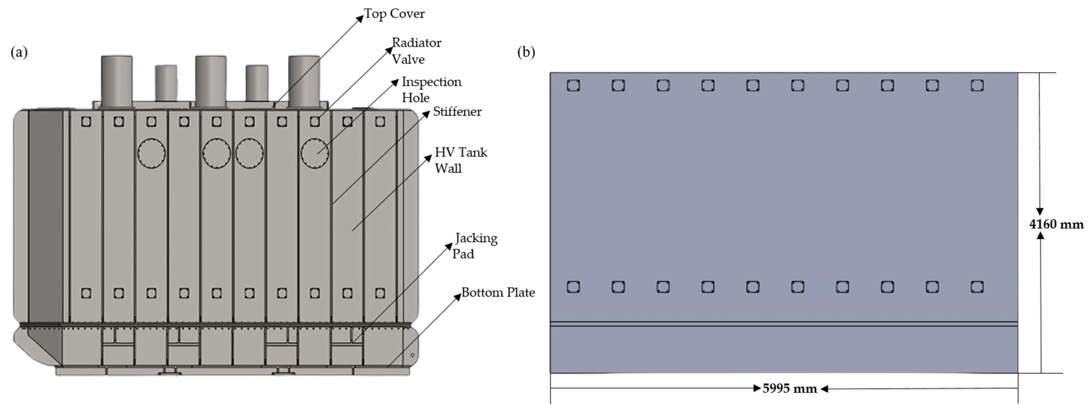
The methodology for optimizing the HV (high-voltage) tank wall in pressure testing involves several steps to ensure accurate analysis and identification of vulnerable areas. Given the complex nature of tank structures, the individual optimization of walls is deemed practical due to dissimilar arrangements and structures among tank walls, which can significantly affect parameters. Thus, the methodology initially focuses on analyzing the entire tank, followed by an individual analysis of the HV tank wall to pinpoint vulnerable sections for pressure testing.
To begin, the entire tank was assessed to understand its structural behavior under pressure. However, individual analysis was prioritized by recognizing that the HV tank wall is often the most vulnerable part due to its design and arrangement within the transformer body. This decision is supported by the observation that the HV tank wall lacks reinforcement elements in other parts of the tank, such as stiffeners in the top cover and base plates/channels in the bottom plate.
The material utilized for analyzing the transformer tank was ASTM A-36. The technical data for this raw material were provided by the supplier of the mild steel plates.
Table 1 outlines the corresponding material properties of ASTM A-36.
The initial phase involved crafting a 3D solid model of the tank using SOLIDWORKS. Subsequently, the solid models were imported into the SOLIDWORKS Simulation program for finite element analysis. The materials’ properties were defined in the simulation module, and fixed support was applied to the four sides of the HV tank wall. Subsequently, a pressure of 0.1 MPa was applied to the tank wall as per the standard IEC 60076-1 article 11.10, representing typical operating conditions [
14].
Table 1.
Material properties of ASTM A-36 [
15].
Table 1.
Material properties of ASTM A-36 [
15].
| Name | ASTM A36 Steel |
|---|
| Model type | Linear Elastic Isotropic |
| Yield strength | 250 MPa |
| Tensile strength | 400 MPa |
| Elastic modulus | 200,000 MPa |
| Poisson’s ratio | 0.26 |
| Mass density | 7850 kg/m3 |
| Shear modulus | 79,300 MPa |
The optimization process involved generating a sample set of parameters and sorting them based on objectives and constraints. Upon conducting a mesh dependency study, it was determined that a mesh size of 25 mm yielded sufficient accuracy for the analysis of the HV tank wall (see
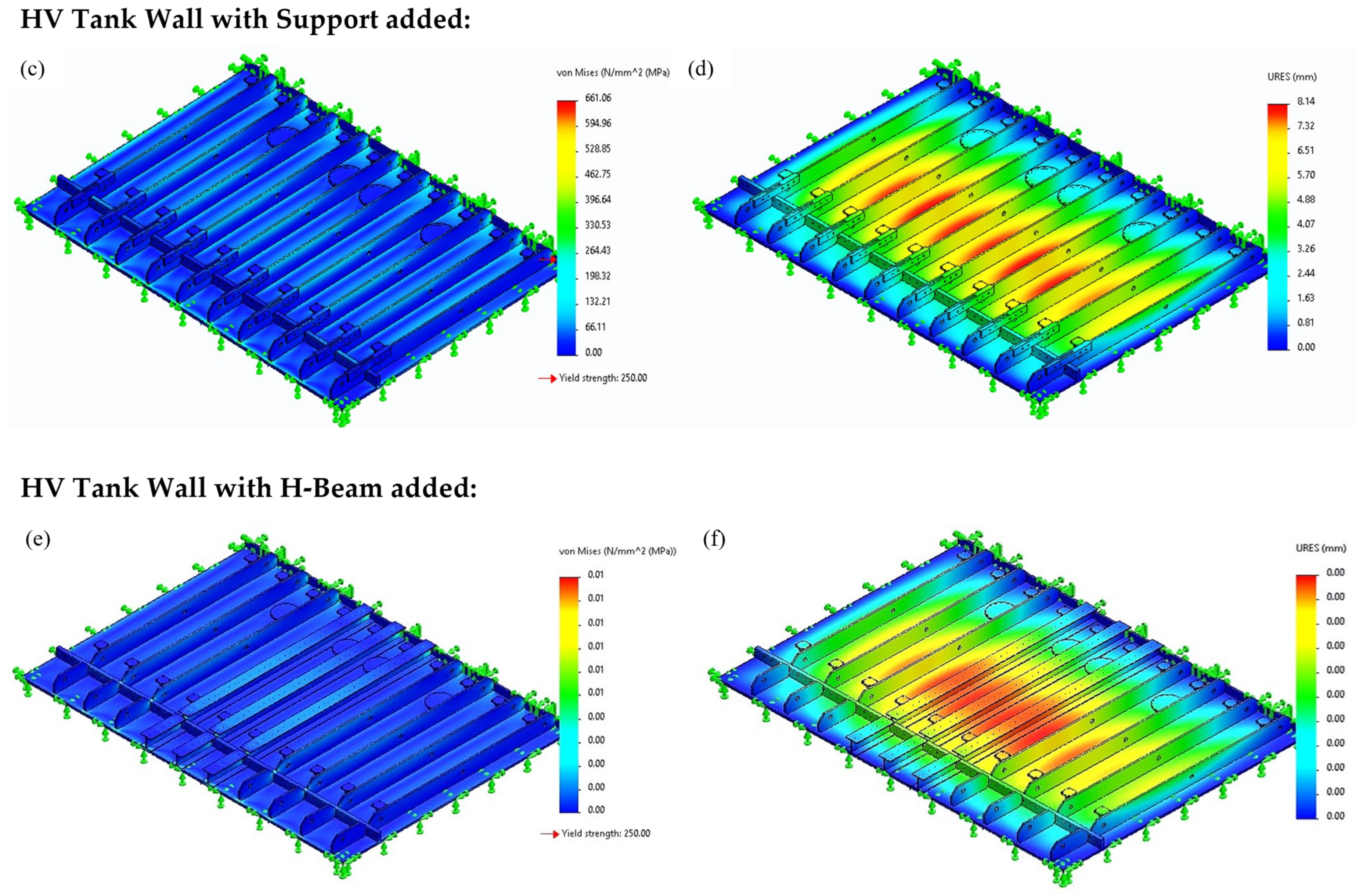
Table 1). The outcome was evaluated to ensure that the maximum deformation and stress values exhibited acceptable differences or were approximately equal, confirming the validity of the optimization process. The primary objectives revolve around geometric mass, maximum stress, and maximum deformation. To begin with, conventional stiffeners were incorporated into the HV tank wall, and the geometric mass, maximum stress, and maximum deformation values were assessed (
Figure 2a,b). Subsequently, flat bars were introduced at every stiffener joint to enhance the structural strength (
Figure 2c,d). Finally, three H beams were installed at the center of the HV tank wall instead of conventional stiffeners, as the center is the most susceptible point to stress and deformation (
Figure 2e,f).
Overall, this methodology enables the identification of vulnerable sections of the HV tank wall through thorough analysis and optimization, ensuring structural integrity and safety during pressure testing.
4. Results and Discussion:
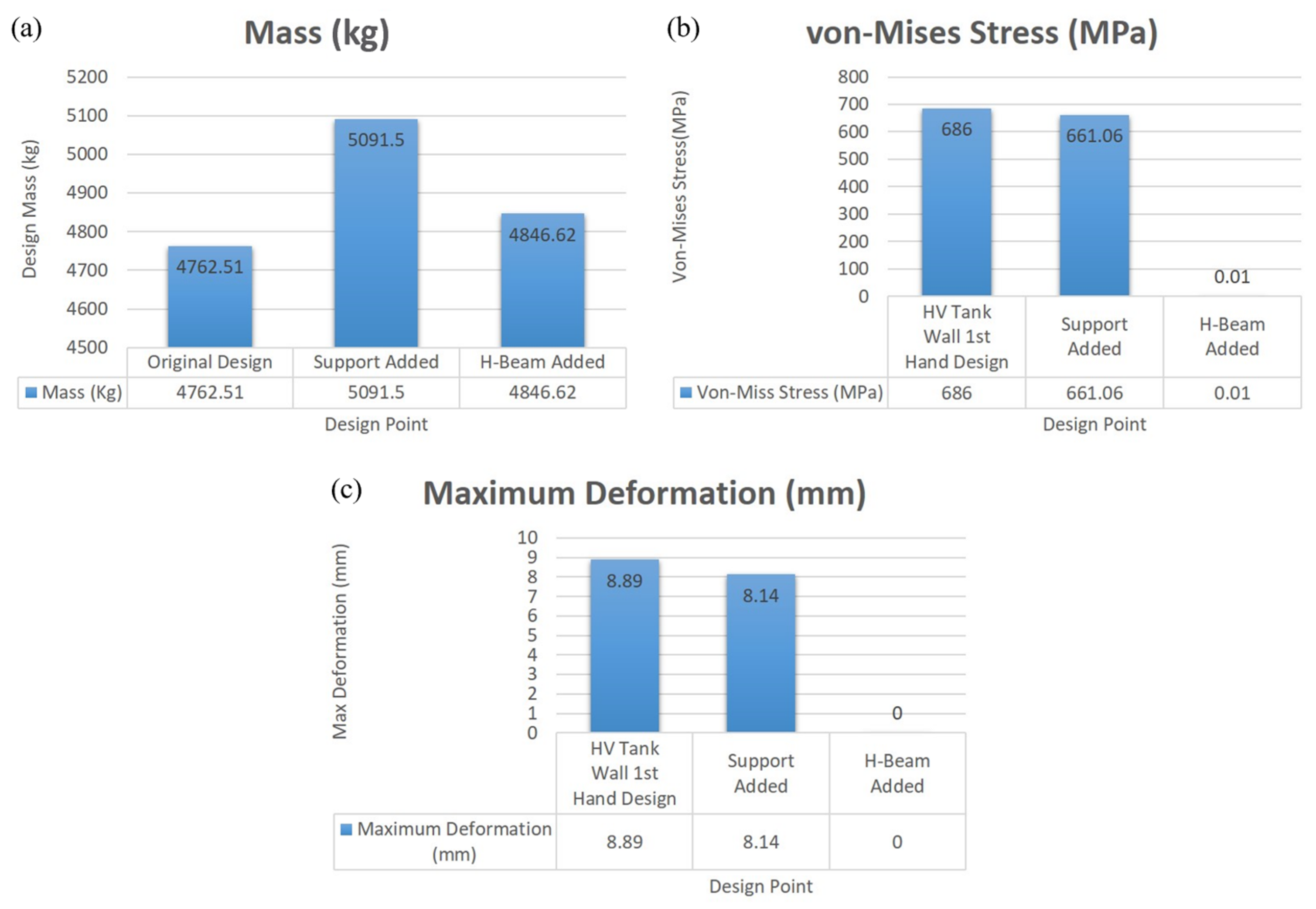
The results of the design iterations for a power transformer tank’s HV (high-voltage) wall have revealed crucial insights into the effectiveness of various structural configurations. Initially, in the original design shown in
Figure 3a, the HV tank wall was constructed without additional support structures, resulting in a substantial mass of 4762.51 Kg, maximum deformation of 8.89 mm, and von Mises stress of 686 MPa (see
Table 2). This design exhibited significant stress and deformation vulnerabilities, particularly evident in the cracks at the welding joints of the stiffeners, both at the bottom and top sections.
To mitigate these issues, support structures were integrated into the second design iteration as shown in
Figure 3b, slightly increasing the mass to 5091.5 Kg while reducing maximum deformation to 8.14 mm and von Mises stress to 661.06 MPa. However, despite this enhancement, the introduced support structures did not entirely eradicate stress and deformation concerns, leaving room for further optimization.
The most notable improvement emerged with incorporating H-beams in the third design iteration (
Figure 3c). By strategically placing three H-beams in the center of the tank wall, the mass decreased to 4846.62 Kg, with both maximum deformation and von Mises stress minimized to negligible levels (0 mm and 0.01 MPa, respectively). This substantial reduction in stress and deformation highlights the efficacy of integrating H-beams as reinforcement elements of designing power transformer tank HV walls.
The use of H-beams provides several advantages. Their strategic placement targets the areas of maximum stress and deformation, which enhances mechanical strength where it is most needed. Moreover, concentrating reinforcement in specific zones reduces the overall material usage, leading to cost savings and increased efficiency. Finally, this targeted reinforcement minimizes stress concentrations, helping to prolong the operational lifespan of the transformer tank.
5. Conclusions and Recommendations for Future Research
In summary, our comprehensive analysis of design iterations for a power transformer tank’s HV wall has yielded invaluable insights into the effectiveness of various structural configurations. Initially, the absence of additional support structures in the first design iteration led to significant stress and deformation vulnerabilities, underscoring the necessity for optimization. Subsequent iterations, notably the integration of support structures in the second design iteration, marked progress in mitigating these concerns, albeit with room for further enhancement.
However, the most substantial improvement was achieved through the strategic incorporation of H-beams in the third design iteration. This innovative approach not only significantly reduced stress and deformation but also optimized material usage, resulting in a stronger and more efficient transformer tank. The targeted reinforcement provided by the H-beams precisely addressed areas of maximum stress, enhancing mechanical strength while minimizing material requirements and stress concentrations.
The utilization of H-beams presents a practical solution for transformer manufacturers seeking to optimize power transformer tank designs. By implementing this advanced structural reinforcement technique, manufacturers can enhance the reliability, efficiency, and longevity of transformer tanks in power distribution systems. This computational analysis offers valuable insights that can guide future design optimizations, ultimately contributing to the advancement of transformer technology and the reliability of power supply infrastructure.
For future work, this paper suggests investigating the impact of varying the wall thickness, stiffener thickness, and stiffener width on the power transformer tank’s performance. This comprehensive approach could lead to significant improvements in the tank’s efficiency, cost-effectiveness, and overall structural integrity. By exploring these additional parameters, researchers can optimize designs to meet the evolving demands of power transformer technology. Additionally, future work related to this paper will involve conducting a detailed thermal analysis of the HV tank wall. This analysis should confirm that any enhancements to the structural design do not compromise the transformer tank’s ability to dissipate heat, thereby ensuring optimal performance during operation effectively.


