Proceeding Paper

Application of the Finite Element Method (FEM) to Analyze the Mechanical Behavior of Piezoelectric Materials When an Electric Field Is Applied to a Piezoelectric Structure (Inverse Piezoelectricity) †

by
Mehdi Boudouh
1,*,
Brahim El Khalil Hachi
1,
Mohamed Haboussi
2 and
Sadam Houcine Habib
1
1
Laboratory of Development in Mechanical and Materials (LDMM), Ziane Achour University, Djelfa PB 3117, Algeria
2
Laboratory of Process and Materials Sciences (LSPM), Sorbonne Paris Nord University, UPR 3407 CNRS, F-93430 Villetaneuse, France
*
Author to whom correspondence should be addressed.
Presented at the 3rd International Electronic Conference on Processes—Green and Sustainable Process Engineering and Process Systems Engineering (ECP 2024), 29–31 May 2024; Available online: https://sciforum.net/event/ECP2024.
Eng. Proc. 2024, 67(1), 13; https://doi.org/10.3390/engproc2024067013
Published: 19 August 2024
(This article belongs to the Proceedings of The 3rd International Electronic Conference on Processes)

Abstract

Modeling the inverse impact of piezoelectricity on the mechanical response of smart (piezoelectric) materials through the finite element method (FEM) requires a comprehensive framework that encompasses a multitude of components and intricacies. The utilization of the FEM by researchers is aimed at scrutinizing and comprehending the complex interplay between the mechanical response and piezoelectric characteristics of smart materials. The process of modeling entails the application of numerical methods that facilitate the examination of the reverse effects of piezoelectricity on mechanical behavior with a high degree of precision and accuracy. Through the FEM, a robust and efficient approach is provided to replicate the intricate behavior and response of smart materials under diverse loading conditions, taking into account the intricate interactions between the mechanical and electrical domains. By adopting this modeling strategy, researchers can acquire valuable insights into the fundamental mechanisms and phenomena that govern the inverse influence of piezoelectricity, thereby laying the groundwork for the advancement of cutting-edge smart materials with enhanced performance and functionality. Consequently, the modeling of the inverse effects of piezoelectricity on the mechanical behavior of smart materials using the finite element method emerges as a pivotal and indispensable facet of material science research, playing a significant role in propelling progress across various domains such as robotics, energy harvesting, and structural health monitoring. The primary aim of this research paper is to simulate the impact of inverse piezoelectricity on the mechanical behavior of piezoelectric materials; we have employed the principles of continuum mechanics to address both mechanical and electrical aspects in order to compute the mechanical field when an electric field is administered to the piezoelectric configuration.

1. Introduction

The phenomenon known as piezoelectricity serves as a crucial connection point between the expansive realms of electromagnetism and acoustics within the field of physics. This phenomenon is particularly intriguing due to the intricate relationship it establishes between electrical properties and mechanical properties, showcasing a fascinating interplay between these two fundamental aspects of physics. The exploration of piezoelectricity offers valuable insights into the interconnected nature of electrical and mechanical quantities, shedding light on the complex dynamics at play within this intriguing phenomenon [1].
For over a century, the utilization of piezoelectricity has facilitated the manipulation of a structure’s mechanical state through the implementation of an electric field. This phenomenon has traversed a diverse array of fields, from measurement techniques exemplified by ultrasonic sensors, to the realm of renewable energy in the form of energy harvesters. It was approximately sixty years ago when piezoelectricity found itself situated within a domain abundant in potential applications, particularly in the arena of low-power electronics [1]. The multifaceted nature of piezoelectricity continues to offer a plethora of opportunities for innovation and advancement across various sectors.
Piezoelectric voltage transformers are devices that utilize both the inverse and direct effects of piezoelectricity, with their operational principle being derived from this combination. One of the key benefits of these transformers lies in their capacity to shrink the size of systems, enabling them to be miniaturized to millimetric dimensions. This feature facilitates their seamless integration into various portable or embedded electronic gadgets such as cameras, mobile phones, flat screens, and others.
Piezoelectric transformers have several advantages over their counterparts in the field of electromagnetic devices. They are characterized by their lightweight nature, typically weighing just a few grams and occupying a volume of less than 1 cm3. Furthermore, these transformers are capable of operating effectively across a broad spectrum of frequencies, ranging from 1 kHz to 2 MHz. They exhibit an impressive voltage gain potential of up to 1000, coupled with a power density that falls within the range of 10 to 100 W/cm3. Another key benefit of piezoelectric transformers is their ability to operate without generating any magnetic noise, making them particularly suitable for applications where noise interference must be minimized [2]. Additionally, these transformers demonstrate a high level of immunity to electromagnetic disturbances, whether they are in the form of radiated signals or conducted interference, thanks to their primary–secondary coupling capacitances typically on the order of picofarads. Lastly, piezoelectric transformers offer exceptional galvanic isolation, providing primary–secondary isolation voltages reaching approximately 5 kV, which is crucial for ensuring safety and preventing electrical hazards in various electronic systems.
Etymologically speaking, the prefix ‘piezo’ originates from the Greek language and signifies the action of pressing or squeezing. Certain materials exhibit a fascinating characteristic wherein they polarize when subjected to mechanical stress, a phenomenon known as the direct piezoelectric effect. In this context, the level of polarization experienced by the material is directly proportional to the applied stress and reverses its sign accordingly. Conversely, the inverse piezoelectric effect occurs when an electric field is applied to a material, resulting in the generation of electric polarization which causes deformation within the same material. It is noteworthy that these piezoelectric effects are exclusive to insulating bodies and are visually represented in Figure 1 for better understanding and illustration. The intricate relationship between mechanical stress, electric fields, and material deformation in the realm of piezoelectricity highlights the complex interplay of physical forces at play. Understanding the principles underlying piezoelectric effects is crucial for various technological applications ranging from sensors to actuators. Moreover, delving deeper into the mechanisms governing these effects can lead to advancements in fields such as material science and engineering. Further exploration of piezoelectric phenomena opens up avenues for innovation and development in diverse sectors of industry and research.
When an electric field E is introduced to case (a), the positively charged cations within the system will exhibit movement towards the direction of the electric field, while the negatively charged anions will move in the opposite direction. It is important to note that due to the varying degrees of rigidity present in the inter-ionic bonds, the softer bonds will experience a more rapid contraction or expansion compared to the harder bonds. Consequently, this disparity in bond strength leads to a deformation denoted as ε that is directly proportional to the strength of the applied electric field. This unique occurrence is commonly referred to as the inverse piezoelectric effect, which underscores the relationship between electric fields and mechanical deformations within the system.
ε = d · E
In the realm of piezoelectric materials, the symbol d represents a crucial parameter known as the piezoelectric constant, which quantifies the ability of a material to convert mechanical stress into electrical charges and vice versa, playing a fundamental role in various applications such as sensors, transducers, and actuators.

2. Theories and Methods

In the domain of linear piezoelectricity, the fundamental equations of linear elasticity are linked to the electrostatic charge equation through the piezoelectric constants. This intricate connection characterizes the behavior of materials under the influence of mechanical and electrical fields. It is crucial to note that the electrical properties involved are not purely static but rather quasi-static due to their interplay with the dynamic mechanical equations. In order to lay a solid foundation for the theoretical framework of piezoelectric materials, it is imperative to provide a comprehensive definition of the mechanical variables and electric field parameters. Moreover, the electrical equations governing the system must also be succinctly outlined to facilitate a thorough understanding of the complex interactions at play within the material. Consequently, a holistic approach that integrates both applied mechanics and electrical principles is essential to unraveling the intricate dynamics of piezoelectric materials [3].

2.1. Mechanical Considerations

By denoting u i , j as the Cartesian component, we are referring to a specific mathematical representation of a minute mechanical shift that occurs at a particular location within a material. This designation allows for a detailed analysis of the displacement’s direction and magnitude in a systematic manner. The strain tensor is defined by:
ε i j = 1 2 ( u i , j + u j , i )   With   u i , j = u j , i x j
The local, infinitesimal rotation is determined by the antisymmetric aspect of the gradient of mechanical displacements, as indicated in previous studies [4]. This particular component of the gradient plays a crucial role in defining the rotational behavior at a small scale within the material. Understanding this antisymmetric part is essential for accurately predicting the deformation and stress distribution within the material under various loading conditions [4].
The local, infinitesimal rotation within a solid material is dictated by the antisymmetric component of the gradient of mechanical displacements, as indicated in previous studies. When considering the interaction between two distinct sections of a solid substance delineated by an arbitrary surface denoted as S, the nature of this interaction can be elucidated through the vector representation of tensile forces denoted as t acting on the surface. This vector of tensile forces, t, can be mathematically linked to the stress tensor denoted as σ through a specific relationship that allows for a comprehensive understanding of the mechanical behavior within the solid material. By exploring the intricate relationship between the traction vector t and the stress tensor σ , valuable insights can be gained into the underlying mechanisms governing the mechanical response of the material under investigation.
t j = n i t i j
The symbol “ n i ” represents the normal component that is located outside of the surface being referred to.
Finally, the dynamic equilibrium equations can be expressed through a set of mathematical expressions in the form of the following equation utilizing the Einstein summation formalism. These equations play a crucial role in understanding the balance of forces and moments acting on a system, providing a fundamental framework for analyzing the stability and motion of physical systems in various fields of science and engineering:
σ i j , i = ρ ü j
The symbol ρ represents the density of the substance.

2.2. Electrical Considerations

The relationship between the intensity vectors of the electric field E and the electric displacement D is established through the mathematical expression connecting these two fundamental quantities in the study of electromagnetism. This expression serves as a crucial link in understanding the behavior of electromagnetic fields and their interactions in various physical systems:
D i = ε 0 E i + P i
Given the polarization vector P and the vacuum permittivity ε 0 ,
ε 0 = 8.854 · 10 12 F / m
The electric field vector E is obtained through the derivation of the electric potential ϕ .
E i = φ , i
Finally, it is crucial to recognize within the domain of electromagnetism that the electric displacement vector D assumes a pivotal role in upholding Gauss’s theorem, especially in situations devoid of unbound electric charges, thereby underscoring its importance in insulating substances characterized by distinct electrical characteristics. The electric displacement vector D is essential in understanding the behavior of electric fields in materials with no free charges, thus highlighting its significance in the study of dielectric properties and their impact on electromagnetic phenomena:
D i , i = 0

2.2.1. Linear Piezoelectricity

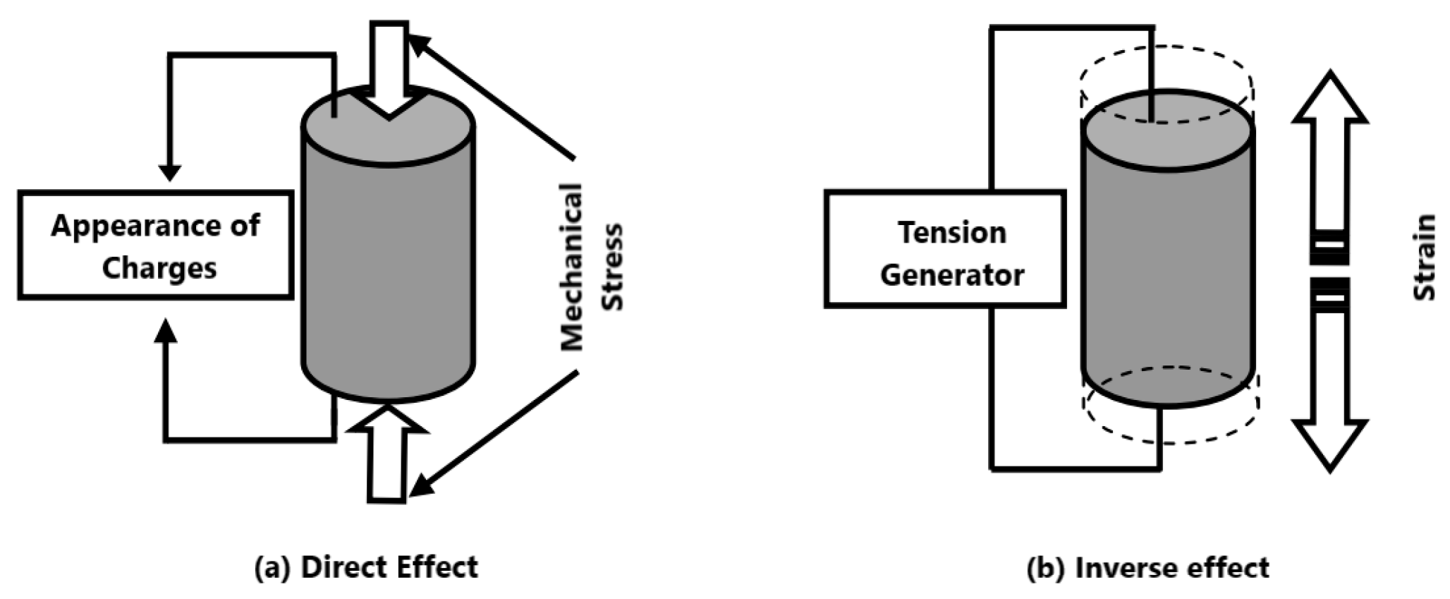
Piezoelectricity emerges as a consequence of the intricate interplay between the electrical energy and mechanical energy inherent in a material, showcasing a fascinating coupling phenomenon. In instances where the pyroelectric effect can be deemed insignificant, the piezoelectric equations effectively establish a profound correlation between a mechanical variable, such as deformation ε or stress σ, and an electrical variable, be it electric induction D or electric field E. These equations serve as pivotal tools in comprehending and characterizing the complex behavior exhibited by piezoelectric materials, shedding light on their unique response to external stimuli. The exploration of these relationships not only enhances our fundamental understanding of piezoelectricity but also paves the way for innovative applications in diverse fields such as sensors, actuators, and energy harvesting devices [5].
σ i j = C i j k l E ε k l e k i j E k
D i = e i k l ε k l ε i j ε E k
σ i j and ε k l are representative of the variables used in the mathematical formulations of stress and strain tensors, which are essential concepts in the study of materials and their mechanical properties, providing a detailed understanding of how materials deform under various conditions and loads. On the other hand, D i and E i symbolize the quantities associated with the induction and electric field vectors, crucial in the field of electromagnetism and electromechanical systems, playing a fundamental role in the analysis and design of electrical circuits, devices, and machines.
The elastic constants, piezoelectric constants, and dielectric constants, denoted as C i j k l E , e k i j , and ε i j   ε respectively, are fundamental properties of materials that are quantified under specific conditions: the elastic constants are measured at a constant electric field E, the piezoelectric constants are determined under constant deformations, and the dielectric constants are evaluated at constant electric field strengths.
A more concise representation using matrix notation is possible by condensing the indices i j or k l into p or q , following the prescribed conventions outlined in Table 1. This method allows for a more streamlined and efficient way of presenting complex mathematical relationships within the matrix framework.
The constitutive equations, which are fundamental in describing the relationships between different physical properties of materials, can be reformulated and expressed in a more concise and structured manner, allowing for a clearer and more systematic representation of the underlying principles governing the behavior of the system:
σ p = C p q E ε q e k p E k
D i = e k q ε q ε i j ε E k
With
ε i j = ε p   when   i = j , p = 1 , 2 , 3
2 ε i j = ε p   when   i j ,   p = 4 , 5 , 6
As well as
C i j k l E = C p q E       e i k l = e i p       σ i j = σ p

2.2.2. General Formalism and Piezoelectric Coefficients

Concerning piezoelectric substances, owing to their anisotropic nature, their attributes are commonly delineated using tensors, which are mathematical entities that comprehensively depict their properties in various orientations and conditions.
The piezoelectric constants (d, e, g, and h) are commonly arranged in matrices with six columns and three rows. Upon transposition, these matrices are represented with a superscript t. Other quantities denoted by superscripts often indicate specific conditions such as constancy or nullity. For example, SE denotes the compliance coefficient under constant or null field conditions, offering valuable insights into the material’s behavior under particular circumstances.
Assuming a voltage denoted by V is applied across two electrodes that are positioned on surfaces perpendicular to the material’s spontaneous polarization, this action leads to a deformation that results in expansion or contraction along direction 3 (A) and directions 1 and 2 (B). In cases where the polarization voltage V is applied to electrodes located on surfaces perpendicular to axis 1, which is also perpendicular to the axis of spontaneous polarization, the deformation experienced by the piezoelectric material will be characterized by shear stresses and strains, indicating a different type of response compared to the previous scenario [6].

2.2.3. Mode of Deformation

Due to the anisotropy inherent in piezoelectric materials, their deformation occurs preferentially in a specific direction when subjected to an electric field E . Understanding the properties of these materials necessitates identifying these preferred directions to comprehend their behavior fully. The characterization of piezoelectric properties relies on a standardized system of symbols and notations, which serves as a common language for researchers and engineers in the field.
Typically, a piezoelectric ceramic is denoted by a trihedron (O, x1, x2, x3) for reference and analysis. As a convention, there is a tendency to interchange the direction with the polarization direction, often associating them with axis 3 or Oz for simplicity and ease of communication among professionals.
To achieve the desired deformation in piezoelectric materials, a potential difference is applied across the faces perpendicular to axis 3. The application of an electric field aligned with the Oz axis results in three distinct deformation modes, as illustrated in Figure 2 of the relevant literature. The coupling modes, crucial for understanding material behavior, are specified by a pair of numerical values: the first representing the direction of the electric field applied, and the second indicating the axis along which deformation occurs [7].
By comprehensively studying these coupling modes and understanding the relationship between applied fields and resulting deformations, researchers can gain insights into the intricate behavior of piezoelectric materials under different conditions. The ability to control and manipulate these deformation modes is essential for various technological applications, such as sensors, actuators, and transducers, where precise and efficient conversion between electrical and mechanical energy is crucial.
Moreover, the systematic analysis of piezoelectric properties and their corresponding symbols and notations enables a unified approach towards studying and utilizing these materials across different disciplines and industries. This standardized system fosters collaboration and knowledge-sharing among experts, facilitating advancements in the development of innovative technologies and applications leveraging piezoelectric effects.
In conclusion, the identification and understanding of directional preferences in piezoelectric materials, as well as the systematic representation of their properties through standardized symbols and notations, are fundamental for advancing research and applications in this field. By delving into the specifics of coupling modes and deformation behaviors, researchers can unlock the full potential of piezoelectric materials for a wide range of technological advancements and innovations [8].
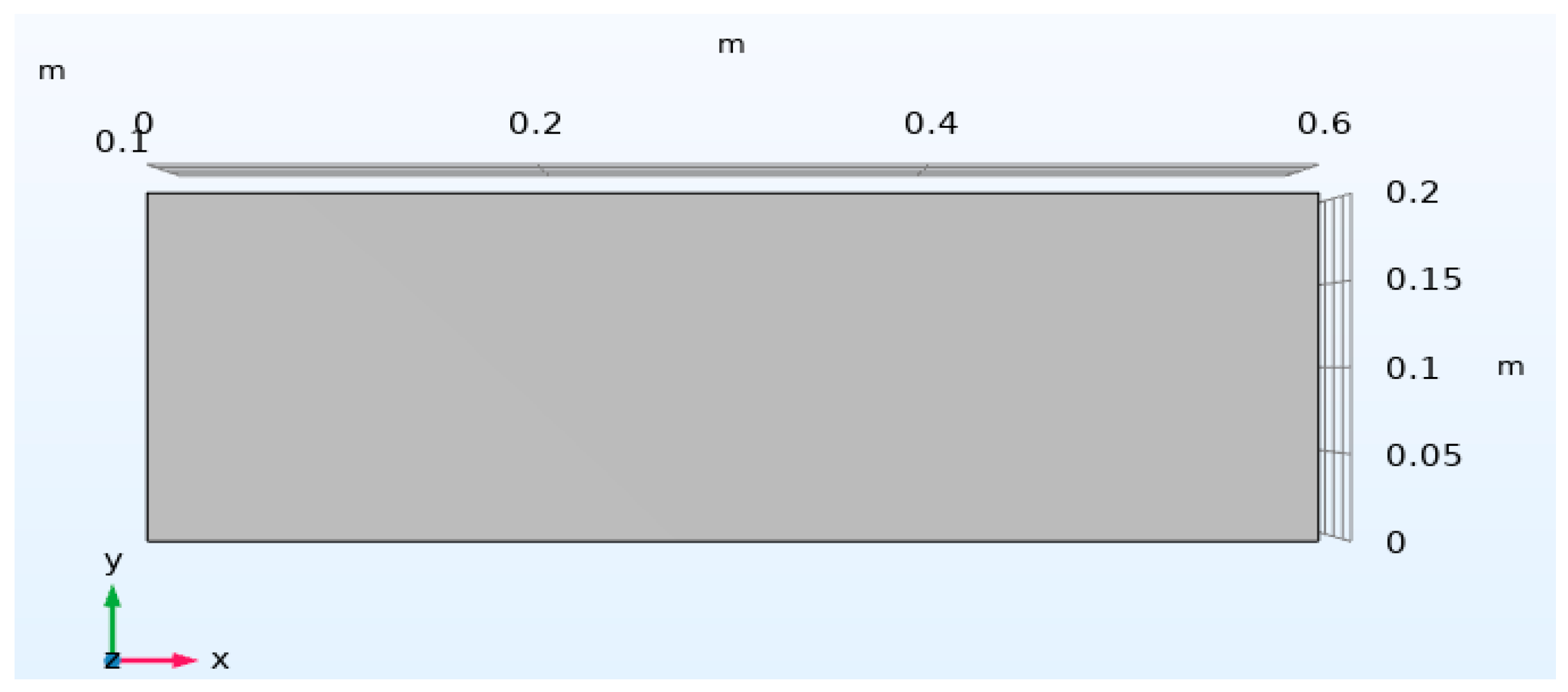
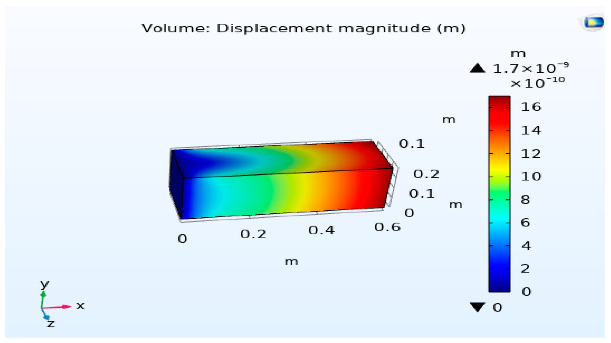
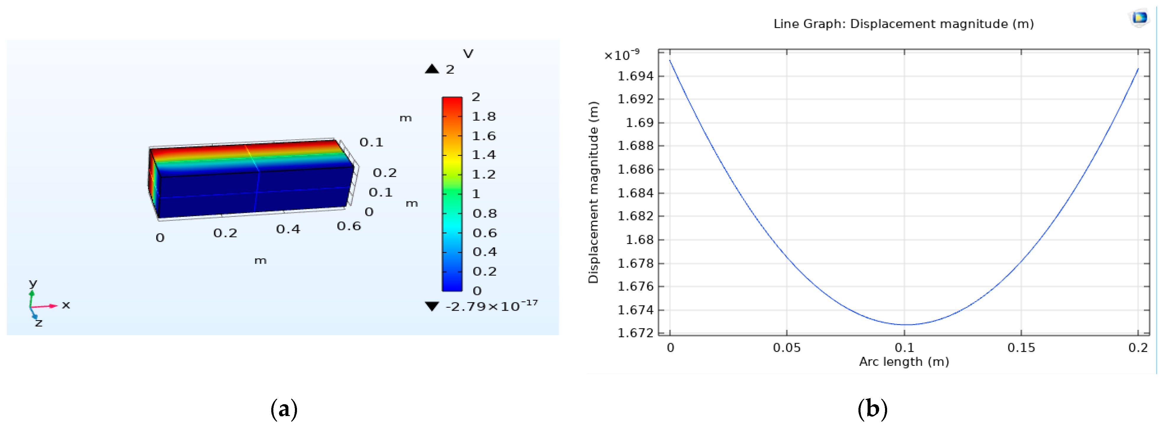
For the purpose of investigating the reverse impact of piezoelectricity, a numerical simulation is conducted on a beam made of PZT piezoelectric material with an opposite polarity configuration. Upon the application of an electric voltage in a transverse manner to the thickness of the beam, the internal deformations occurring within the two layers of piezoelectric material generate control forces that result in the bending of the piezoelectric beams. This process is crucial for understanding the behavior of piezoelectric materials under specific conditions and can have significant implications for various applications. The detailed geometry of the system under consideration is visually represented in Figure 3, providing a visual aid for comprehending the experimental setup and configuration.
The specific material chosen for this investigative study is a type of piezoelectric ceramic known as PZT-5H, renowned for its unique properties and suitability for such applications. In this experimental setup, the beam is subjected to a unit voltage denoted as V, which is precisely applied to the terminals of the electrodes connected to the piezoelectric material. This controlled application of voltage allows for the precise manipulation of the piezoelectric beam and facilitates the observation of its behavior under varying conditions and electrical stimuli. Such detailed analyses are essential for advancing our understanding of piezoelectric materials and their applications in diverse fields ranging from engineering to biomedical sciences. The utilization of numerical simulations in this context enables researchers to explore the complex interactions and responses exhibited by piezoelectric materials, paving the way for innovative technological developments and scientific discoveries in the realm of materials science and engineering.

3. Results

To ascertain the value of the displacement related to the applied electric field, numerical simulations were conducted using COMSOL Multiphysics®. The application of an electric field to the piezoelectric components of the beam leads to a well-demonstrated displacement magnitude, as depicted in Figure 4.
The outcomes derived from these simulations, with regard to displacement isovalues U x and von Mises stress, can be observed in both Figure 4 and Figure 5. These simulations indicate that with an electric field intensity of 2 V , the deformation observed on the micro clamp amounts to approximately 1.7 · 10 9   m . The region of maximum deformation corresponds to the location of the object being carried, situated at the end of the multilayer bar.
The electrical potential is illustrated in Figure 6a. Additionally, Figure 6b displays the curve of displacement magnitude in relation to the arc’s length.

4. Conclusions

This research endeavor has effectively underscored the advantages of Multiphysics modeling within the realm of piezoelectric materials, owing to the fact that these materials exhibit a dual behavior. The first aspect of this behavior pertains to their electrical response, which is induced by the application of a mechanical load. The second aspect involves their mechanical behavior, which is triggered by the application of an electric field. Nevertheless, it is imperative to emphasize that there is an ongoing need for further research and development in relation to these intelligent devices and structures, with a specific focus on various crucial aspects. These aspects include but are not limited to the optimization of their design, and the careful selection of suitable multifunctional materials that possess the necessary strength and capability to withstand significant electrical loads. This selection ensures that the materials remain structurally sound and do not undergo any deformations during their operational use. Additionally, attention must be given to identifying the most appropriate behavioral laws that govern the interactions within these materials, as well as refining their manufacturing processes to enhance efficiency and effectiveness. All of these endeavors should be approached with a commitment to adopting a relatively simplified methodology for comprehending the underlying physics of the phenomena at play, which is commonly referred to as “Linear piezoelectricity”.
Future research endeavors and the proposed subsequent actions involve delving into the intricate realm of plastic behavior in materials subjected to electrical loading, as well as exploring the consequential impact of fracture phenomena within such conditions.

Author Contributions

Conceptualization, M.B.; software, M.B. and B.E.K.H.; validation, M.B. and B.E.K.H.; formal analysis, M.B. and S.H.H.; resources, M.B. and B.E.K.H.; data curation, M.B. and S.H.H.; writing—original draft, M.B.; writing—review and editing, M.B., B.E.K.H. and M.H.; supervision, M.B. and B.E.K.H.; project administration, M.B., B.E.K.H. and M.H.; funding acquisition, M.B., B.E.K.H. and M.H. All authors have read and agreed to the published version of the manuscript.

Funding

This research received no external funding.

Institutional Review Board Statement

Not applicable.

Informed Consent Statement

Not applicable.

Data Availability Statement

The original contributions presented in the study are included in the article, further inquiries can be directed to the corresponding author.

Acknowledgments

M. Boudouh, B. E. K. Hachi, and S. H. Habib acknowledge the financial support of DGRST as part of the Short-Term Mobility and Development Program Abroad (Ministerial Resolution 255 of 25 February 2024).

Conflicts of Interest

The authors declare no conflicts of interest.

References

  1. Viguier, C. Contribution au Développement D’actionneurs Electroactifs pour L’assistance Circulatoire: Application à la Mise au Point d’une Fonction Antithrombotique; Energie Electrique, Institut National Polytechnique Toulouse: Toulouse, France, 2005. [Google Scholar]
  2. Endo, A.; Sasaki, N. Investigation of Frictional Material for Ultrasonic Motor. Jpn. J. Appl. Phys. 1987, 26, 197. [Google Scholar] [CrossRef]
  3. Boudouh, M.; Hachi BE, K.; Taibi, H.; Haboussi, M.; Raga, M.F.; Hachi, D. Modeling Fracture Properties for Heterogeneous Materials Using J-Integral. Eng. Proc. 2023, 56, 277. [Google Scholar] [CrossRef]
  4. Baz, A.; Poh, S.; Muta, M.; Gilheany, J. Active control of Nitinol-reinforced beam. In Intelligent Structural Systems; Springer: Dordrecht, The Netherlands, 1992; pp. 169–212. [Google Scholar]
  5. Paine, J.S.N.; Rogers, C.A.; Smith, R. Adaptative composite materials with shape memory alloy actuators for cylinders and pressure vessels. J. Intell. Mater. Syst. Struct. 1995, 6, 210–219. [Google Scholar] [CrossRef]
  6. Kuri Bayashi, K. A new actuator of a joint mechanism using TINI alloy wire. Int. J. Robot. Res. 1986, 4, 47–58. [Google Scholar] [CrossRef]
  7. Airmar Technology Corporation, Piezoflex Polymer. 2004. Available online: www.airmar.com (accessed on 4 November 2023).
  8. Physik Instrumente (PI) GmbH & Co. KG. Tutprials: Electrostrictive Actuators. 2005. Available online: www.physikinstrumente.com (accessed on 7 August 2020).
Figure 1. Illustration of the direct (a) and inverse (b) piezoelectric effects.
Engproc 67 00013 g001
Figure 2. Fundamental vibration modes of a piezoelectric ceramic.
Engproc 67 00013 g002
Figure 3. Dimensions of the beam used in the simulation by COMSOL Multiphysics®5.6.
Engproc 67 00013 g003
Figure 4. Displacement magnitude.
Engproc 67 00013 g004
Figure 5. von Mises stress.
Engproc 67 00013 g005
Figure 6. (a) The electrical potential; (b) the curve of displacement magnitude as a function of the length of the arc.
Engproc 67 00013 g006
Table 1. Matrix notation.
ij or klp or q
111
222
333
23 or 324
31 or 135
12 or 216
Disclaimer/Publisher’s Note: The statements, opinions and data contained in all publications are solely those of the individual author(s) and contributor(s) and not of MDPI and/or the editor(s). MDPI and/or the editor(s) disclaim responsibility for any injury to people or property resulting from any ideas, methods, instructions or products referred to in the content.

