Abstract
Friction stir welding (FSW) is a pivotal solid-state method revolutionizing metal joining diverse manufacturing sectors. This study explored the transformative potential of FSW in welding various metal types, both ferrous and nonferrous, by its ability to create a minimal heat-affected zone (HAZ), thereby mitigating alterations to the microstructure. This research delved into the utilization of filler materials during the FSW process. The investigation centers on scrutinizing the microstructure within the weld nugget area of FSW, employing a 3.1 mm thick aluminum 6061-T6 sheet in a butt joint configuration. Brass and zinc, each 0.2 mm thick, were selected as fillers. Microstructural analyses conducted via scanning electron microscopy (SEM) and energy dispersive X-ray spectroscopy (EDS) specifically targeted the weld nugget and HAZ regions. The EDS analysis revealed a higher presence of zinc fillers within the weld nugget than brass, indicating more evenly dispersed grains. SEM observations also highlighted larger grain sizes associated with brass, which could lead to welding defects such as voids and cracks. As such, the study concluded that using zinc fillers manifests a superior microstructure compared to brass during the FSW process involving aluminum 6061-T6.
1. Introduction
The welding technique is one of the procedures in the manufacturing industry that continually requires development. The need for new techniques continues to rise alongside improvements in quality and quantity, driven by intense industrial competition. Welding techniques find extensive application in joining processes due to their lightweight characteristics and relatively simple procedures, resulting in comparatively lower costs [1,2].
A novel method in the welding process, friction stir welding (FSW), has been discovered. Friction stir welding falls under the solid state welding (SSW) category, wherein metals being joined do not melt (remaining in a solid state) during the joining process. The principle of friction stir welding relies on the friction generated by a rotating tool moving along the welding groove on the stationary work piece. The resulting friction creates heat in the welding area under substantial axial pressure. This process operates at relatively low temperatures. Material amalgamation (welded outcome) is achieved through tool movement and mechanical deformation of the work piece material during tool motion [3,4,5].
Qixian Zheng et al. investigated the results of FSW between 6061 Al and 316 stainless steel using Zn as the filler metal [6]. This study achieved hardness in the Al-Zn-steel joints by employing a “sandwich” layered structure. With a tool pin immersed in Zn foil, the Zn was stirred into the aluminum structure, forming an Al-Zn mixing layer within the aluminum part. Meanwhile, at the steel-Zn interface, a thin layer structure of steel-Zn mixing was observed without the presence of intermetallic compound interlayers. In lap joint welding, using Zn foil as a filler metal demonstrated better strength than joints without filler metal [7].
K. Tejonadha Babu et al. performed friction stir butt welding on AA6061 using pure aluminum as a filler plate [8]. Macro and microphotography studies indicated that filler plate deposition had occurred on the welded joint surface. The welded joint employing the filler plate exhibited a 13% decrease in its hardness. This decrease in hardness was attributed to a combined effect of smoothening resulting from deposition and pure aluminum within the stir zone. The tensile strength of the joint using the filler plate reached 60% of the base metal’s tensile strength. Results from the dynamic polarization potential (DPP) test demonstrated an enhancement in corrosion resistance achieved by employing pure aluminum as a filler material in the joint compared to joints without filler material.
Friction stir lap welding was conducted by several researchers using different materials, Al1A99 and pure Cu, employing Zn as the filler metal with a “pinless” tool configuration [5,9,10,11]. This study focused on comprehending the interlayer of FSW, distinct from copper plates with a thickness of 2 mm and aluminum plates with a thickness of 2 mm. They utilized a 0.2 mm-thick zinc foil as the filler metal with a pinless tool. Macro and micro-observations were made concerning welding temperatures under different interlayer material parameters and weld properties. Experimental observations revealed that interlayer thickness decreased with increased rotational speed and decreased transverse speed. However, rotational speed played a more crucial role in this process, supported by data from thermo-testing recorded via type-K thermocouples. Specific investigations were conducted to study the evolution behavior of these interlayers. Mechanical properties significantly correlate with the interlayer, microstructure, and diffusion-extrusion levels. In this study, microhardness increased on the Cu side due to interdiffusion on the Al side caused by interdiffusion and extrusion. Successful welding was achieved at a rotational speed of 1600 rpm and a transverse speed of 20 mm/min, exhibiting the highest combined strength without weld keyhole formation.
The researchers conducted a metallurgical and mechanical study on different FSW combinations involving aluminum 1050 and brass (CuZn30) [9,12]. This research investigated the influence of FSW parameters on the mechanical and metallurgical properties of joints between aluminum 1050 and brass (70% Cu–30% Zn). Microstructure and chemical composition were examined using optical microscopy, SEM, X-ray, and EDS analysis. Mechanical properties were evaluated through hardness testing and tensile strength measurement of the welded joints. Key parameters investigated in this study included tool rotation speed, offset, welding speed, and the depth of pin tool penetration.
This study’s maximum ultimate tensile strength was 80% of the base metal (aluminum). Research findings indicated that optimum parameters resulted in defect-free joints originating from material flow and narrow multilayer intermetallic compounds at the interface in addition to composite structures within the stir zone, leading to robust joint formation.
This study was conducted to ascertain the differential effects of incorporating brass and zinc filler plates in friction stir welding on the strength of welded joints in 6061-T6 series aluminum plates. SEM images and EDS were employed to analyze the microstructure, aiming to assess the formability capability of the welding outcomes.
2. Research Method
The primary material used was aluminum 6061-T6, with a thickness of 3.1 mm. Welding was performed via the friction stir welding (FSW) method and a butt joint connection. The filler material included a brass plate and zinc plate with a thickness of 0.2 mm each. Full welding parameters can be seen in Table 1.

Table 1.
Parameters of friction stir welding.
The instrument used to perform microstructure analysis of welded specimens was a scanning electron microscope (SEM) equipped with an energy dispersive X-ray spectroscopy (EDS) system, with brand JEOL type JSM-6510.
3. Results and Discussions
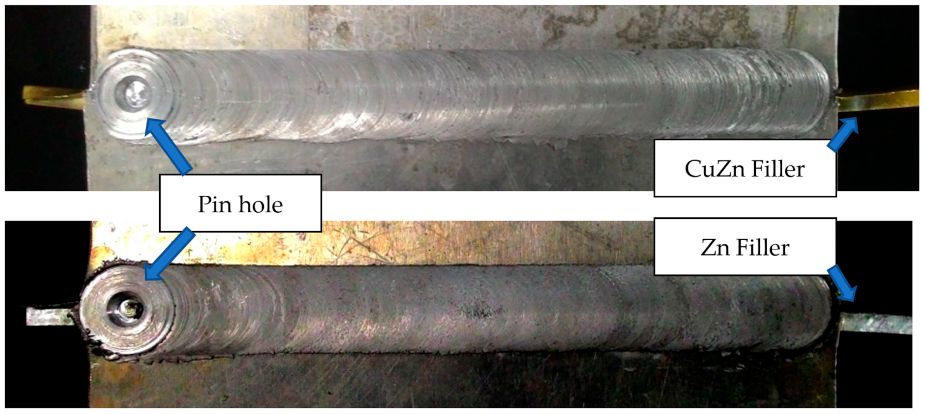
The welding process of the two specimens was stable, and the results of friction stir welding showed that the two specimens had a smooth surface with a relatively high welding temperature. The welding temperatures for both specimens were 245.81 °C (with brass filler) and 255.9 °C (with zinc filler). The weld results showed a rough surface and some cavities, as shown in Figure 1.

Figure 1.
The results of the FSW of aluminum 6061-T6 with CuZn and Zn fillers.
Specimen 1 was the result of welding aluminum 6061-T6 using the FSW method with the application of brass filler. The welding parameters included a rotational speed of 1250 rpm and a feed rate of 10 mm/minute, producing welds of sufficient quality. Visually, the joint surface on Specimen 2 appeared smooth. The brass filler inserted between the 6061-T6 aluminum layer was successfully stirred and mixed in the stir zone. Weld flash appeared on the upper surface of the weld nugget due to the high welding temperature. Excessive welding temperatures can cause the 6061-T6 aluminum material to become very soft, causing some softened material to blow out of the stir zone as the shoulder and pin stir the aluminum material and brass filler. The results of the welding temperature measurement of Specimen 1 using a thermocouple showed an average welding temperature of 245.811 °C.
Specimen 2 was the result of welding aluminum 6061-T6 via the FSW method using zinc filler. Welding parameters included a rotational speed of 1250 rpm and feed rate of 10 mm/minute, producing welds with satisfactory quality. Visually, the joint surface on Specimen 2 appeared smoother than on Specimen 1. The zinc filler applied between the 6061-T6 aluminum layer was successfully stirred and mixed in the stir zone. The presence of weld flash, similar to Specimen 1, was due to the high welding temperatures. The average welding temperature of Specimen 2 reached 255.9 °C, exceeding the temperature of Specimen 1.
Figure 2 shows the results of the quantitative analysis of the chemical composition of the FSW weld joint of aluminum 6061-T6 with brass filler. In EDS analysis, the colors usually correlate to certain components found in the sample. The peaks in the spectrum correspond to the distinct energies at which each element emits X-rays. EDS analysis software frequently colors these peaks differently to make it simpler for the user to determine which elements are present in the sample. The quantitative analysis indicated that EDS successfully detected the presence of five types of elements, with relative abundances of C (carbon) (19.71%), O (oxygen) (3.06%), Al (aluminum) (73.14%), Cu (copper) (2.87%), and Zn (zinc) (1.22%). The distribution of these elements is visualized in Figure 3, which was produced via microphotography.
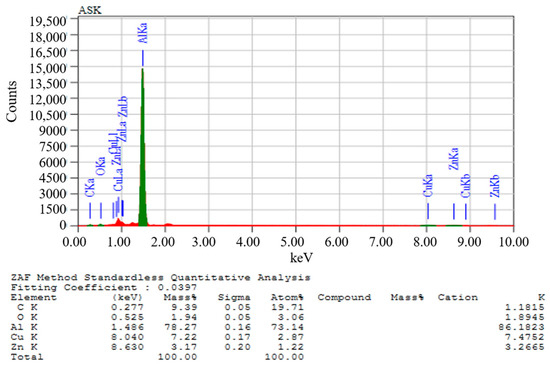
Figure 2.
Quantitative analysis of FSW weld composition of aluminum 6061-T6 with brass filler.

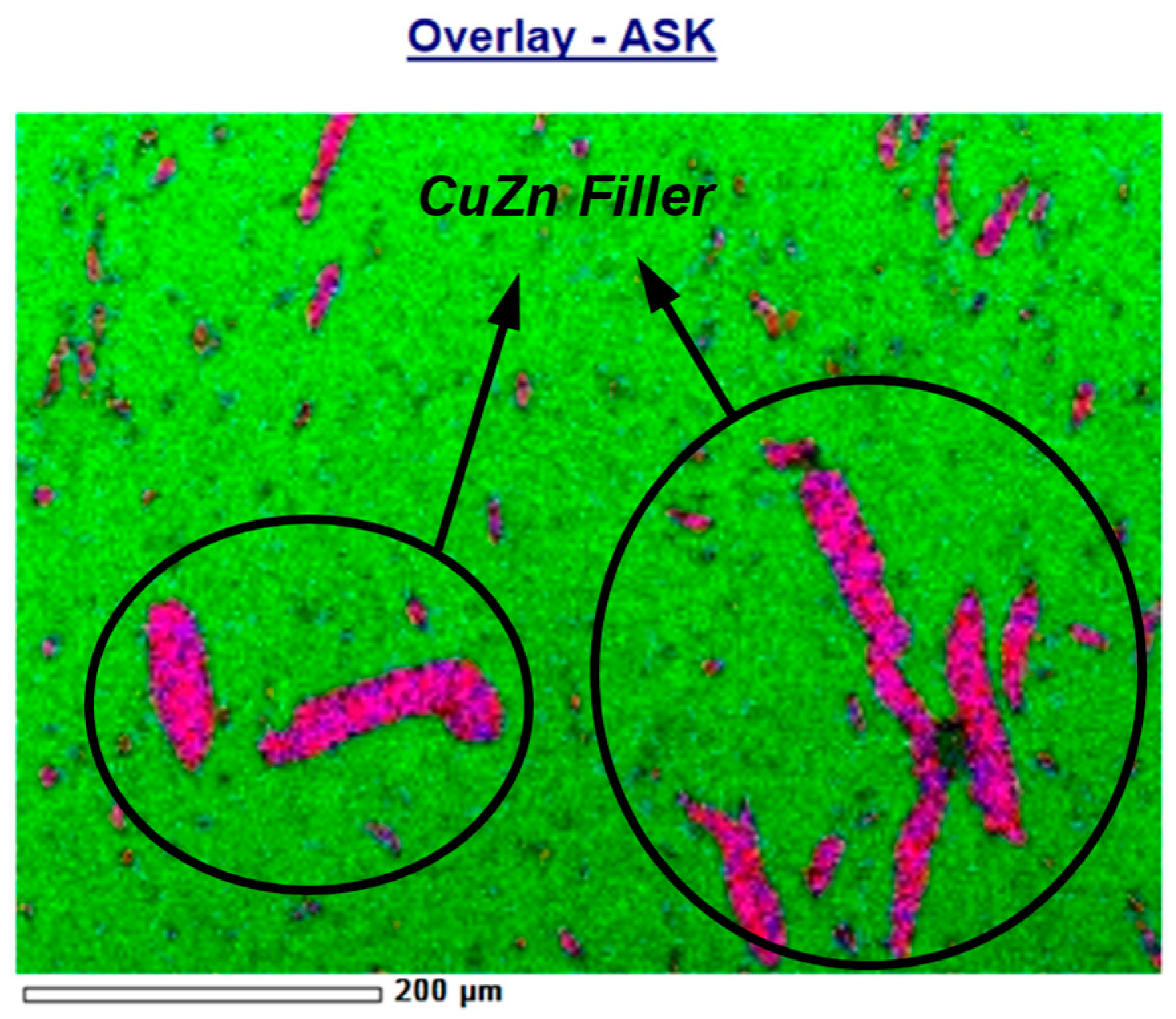
Figure 3.
Elemental distribution map on FSW weld joint of aluminum 6061-T6 with brass filler.
Line analysis using the mapping program showed that the atoms of Cu and Zn that made up the brass filler were distributed less smoothly and evenly. Line analysis involves generating a straight line (indicated in red), with the overlapping blue and magenta colors indicating the presence of copper (Cu) and zinc (Zn) elements. There was a large enough piece of brass crystal among the other fragments in the sample pieces analyzed. The brass filler was less stirred and perfectly mixed in the nugget matrix. The result of the line analysis of the FSW weld joint of aluminum 6061-T6 with brass filler can be seen in Figure 4.
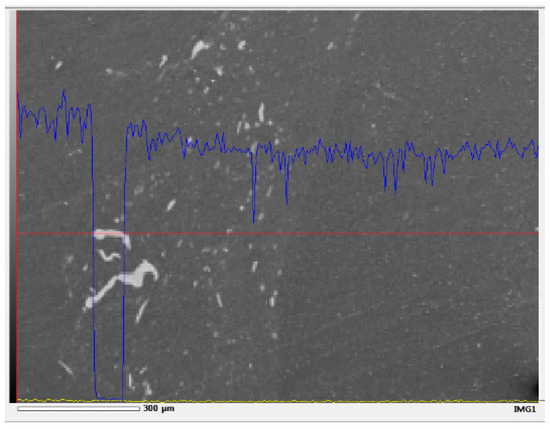
Figure 4.
Line analysis FSW weld connection aluminum 6061-T6 with brass filler.
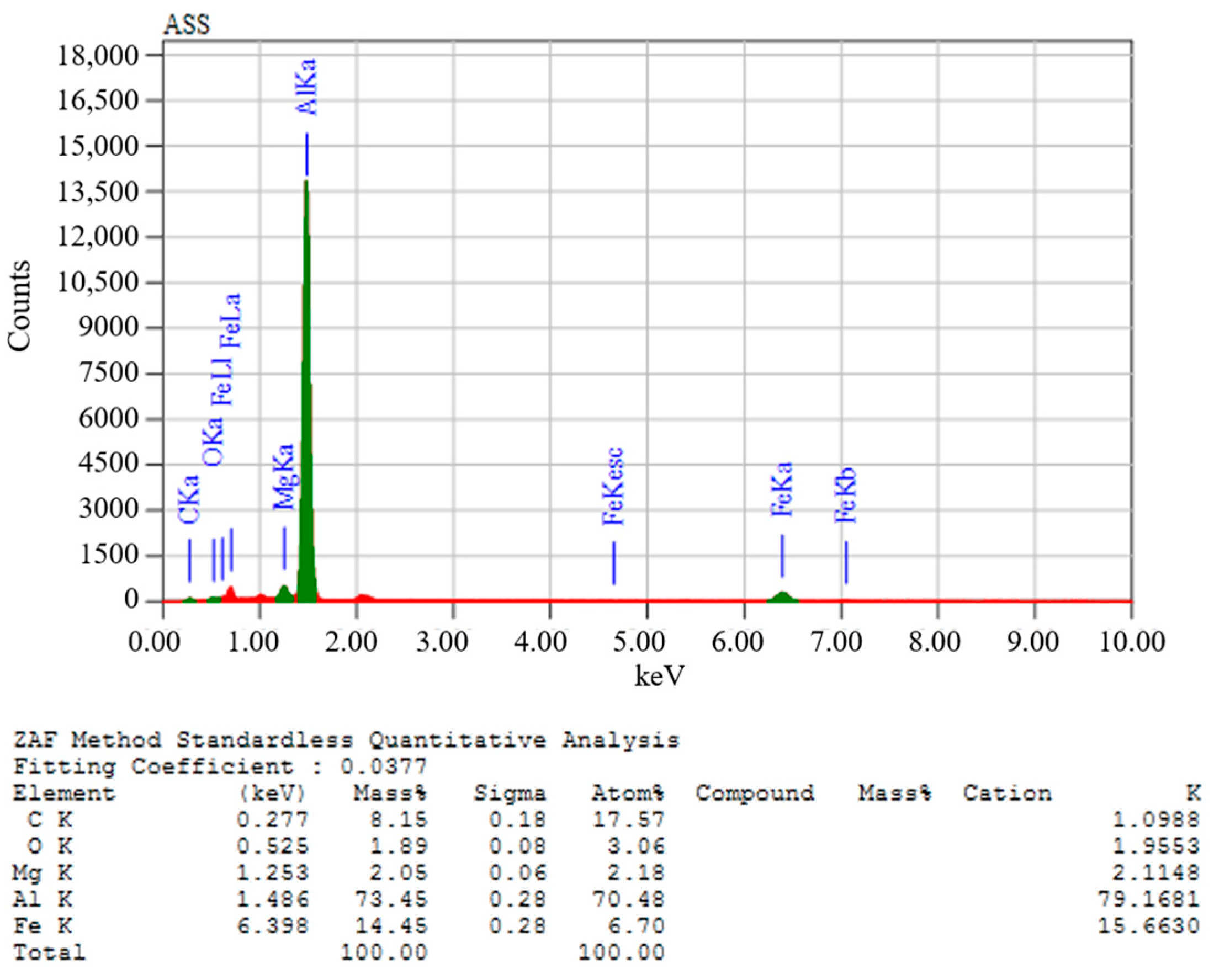
Figure 5 shows the results of the quantitative analysis of the chemical composition of the FSW weld joint of aluminum 6061-T6 with zinc filler. Color disparities analyzed through EDS signify differences in the detected chemical elements, simplifying the sample’s identification process. The quantitative analysis showed that EDS detected the presence of five types of elements with their respective relative abundance: C (carbon) (17.51%), O (oxygen) (3.06%), Mg (magnesium) (2.18%), Al (aluminum) (70.48%), and Fe (iron) (6.70%). The distribution of these elements can be seen visually in Figure 6.
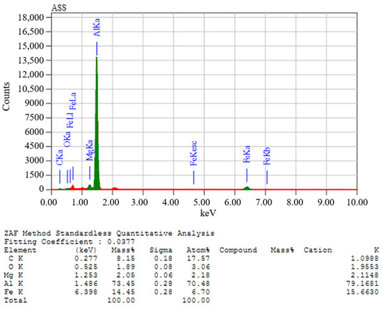
Figure 5.
Quantitative analysis of FSW weld composition of aluminum 6061-T6 with zinc filler.
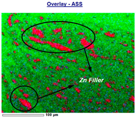
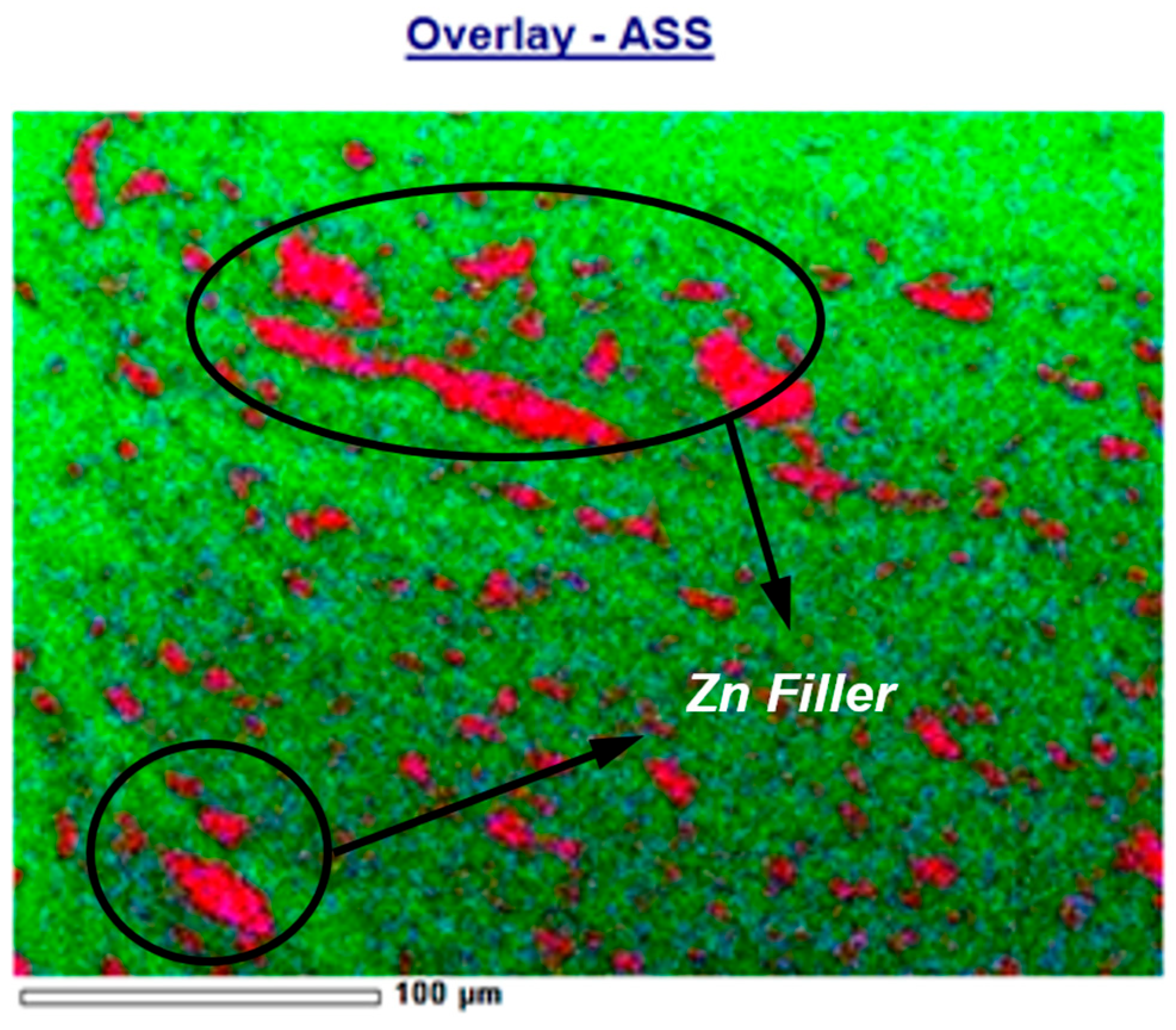
Figure 6.
Elemental distribution map of zinc filler on aluminum 6061-T6 FSW weld joint.
Line analysis using the mapping program showed that the atoms of the elements Mg and Fe (some metal elements that form alloys with zinc) that make up the zinc filler were distributed relatively evenly. In the analyzed sample pieces, there were many zinc alloy crystals with sizes varying from medium to small. The zinc filler was stirred and mixed perfectly in the nugget matrix.
In this study, scanning with a scanning electron microscope (SEM) was mainly used to detect the presence of weld defects in the weld joint area, especially in the nugget area near the HAZ (heat-affected zone). The defect can be a void or a crack. The results of scanning with SEM can also be used to know the size and distribution of metal crystal grains resulting from welding both base metal and filler. Figure 7 shows the scanning results with SEM of the FSW weld joint of aluminum 6061-T6 with brass filler at two magnification levels, 200 and 1000 X. At 200 X magnification (Figure 7a), no weld defects, such as voids or cracks were visible. The scanning results only showed the dispersion of the brass filler crystal grains in the aluminum matrix. In addition to many small crystalline brass grains scattered in the aluminum matrix, there were also some large grains with lengths of up to 100 μm or 0.1 mm. Many large crystal grains can be caused because the brass filler does not ideally undergo deformation (destruction process) during welding.
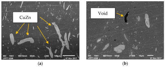
Figure 7.
SEM photo for FSW aluminum 6061-T6 with brass filler at (a) 200 and (b) 1000 X magnification.
At 1000 X magnification (see Figure 7b), weld defects in the form of voids were visible in some places. Specifically, at the scanning position, a void was found with a length of up to 20 μm and a width of 4 μm. Several small spherical (dot-like) voids with a diameter of less than 1 μm were also found. Most of these voids were found within the aluminum matrix rather than at the edges of the brass filler granules. The defect was formed due to the imperfect reformation of the aluminum base metal during the FSW process and was not caused by the filler material. The presence of defects and large crystal grains can reduce the mechanical properties of the weld.
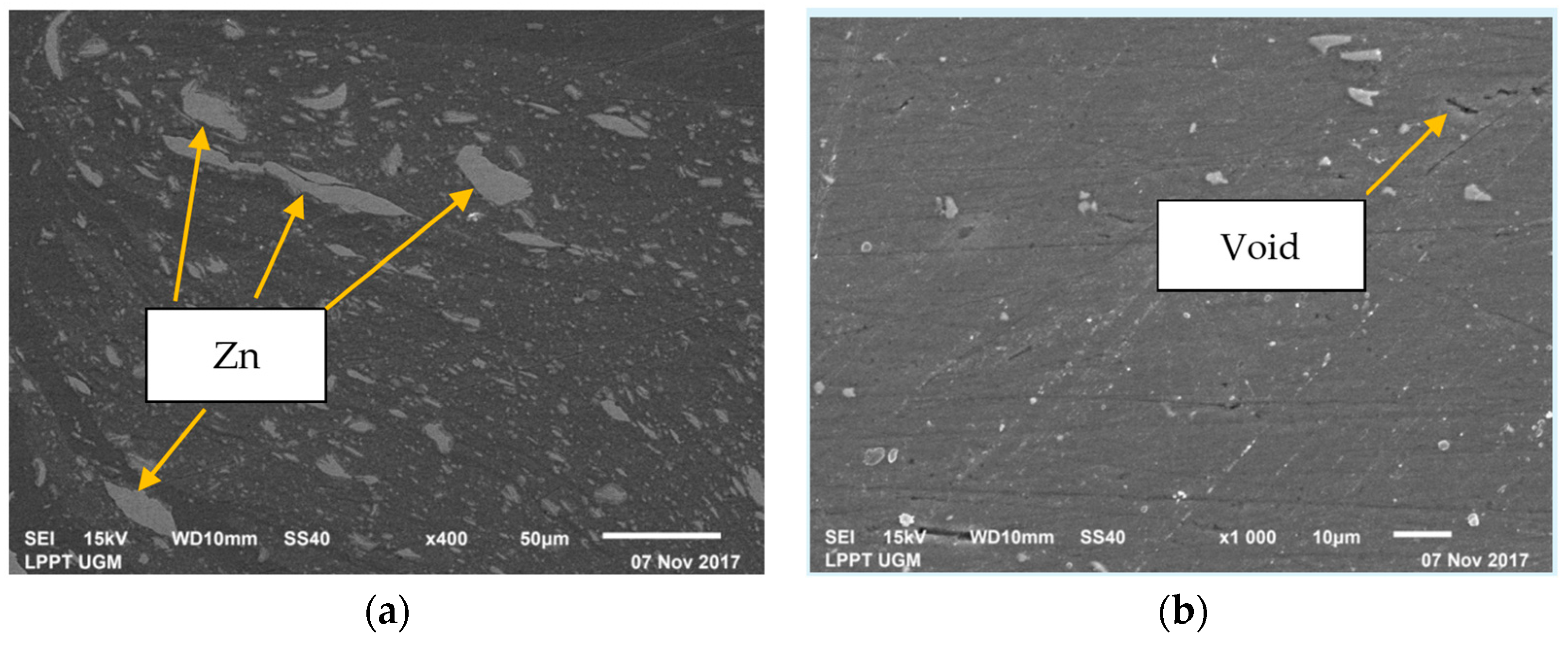
Figure 8 shows the scanning results with SEM for the FSW weld joint of aluminum 6061-T6 with zinc filler. There were two levels of magnification, 400 and 1000 X. At a magnification of 400 times (see Figure 8a), no weld defects, such as voids or cracks, were visible. Scanning results showed the dispersion of zinc filler crystal grains in the aluminum metal matrix. The size of zinc crystal grains appeared to vary from small to large. The largest grain size reached a length of 50 μm or 0.05 mm. As in Specimen 1 (brass filler), many large crystal grains existed. It can be caused because the zinc filler did not undergo deformation (destruction process), ideally during the FSW process.

Figure 8.
SEM image of FSW aluminum 6061-T6 with zinc filler at two different magnifications: (a) 200 and (b) 1000 X.
At a magnification level of 1000 X (see Figure 8b), there were visible weld defects in the form of voids in some places. Unlike Specimen 1 (brass filler), the void found was minimal in size and round in shape (like a dot). The size of the void diameter was less than 1 μm and was only detected in one or two places. All voids were in the aluminum matrix. The void was not due to the addition of filler. Voids occurred due to the FSW process on aluminum material caused by trapped air or dirt particles.
The results of FSW welding of aluminum 6061-T6 with CuZn and Zn filler showed good macro structure visually. The surface of both specimens appeared smooth, and the welding process was stable. The addition of Zn filler gave a higher average welding temperature when compared with CuZn filler. This resulted in a more perfect deformation and metal integration on welds with zinc filler.
In Specimen 1, the intermolecular voids in the aluminum base metal matrix were numerous but relatively small, and there was a large void (filled with a brass filler). In Specimen 2, the intermolecular voids in the aluminum base metal matrix were numerous, and there were several large voids (which were filled with zinc filler). It showed that the proportion of zinc filler mixed in the aluminum base metal matrix was more significant than that of brass filler. This interpretation was consistent with the results of a quantitative analysis showing that the relative abundance of aluminum in Specimen 2 was 70.48%. In Specimen 1, the amount was more significant at 73.14%. The smaller relative abundance of the aluminum element indicated that the relative abundance of the other elements (including the filler) was more remarkable. It meant that the proportion of the filler mixed into the weld was more significant. Microstructure analysis based on EDS concluded that zinc was more suitable for alloying with aluminum base metal as a filler than brass.
SEM results also showed that Specimen 2 had a better arrangement and distribution of filler crystals than Specimen 1. The grain size variation of zinc crystals was relatively smaller than the grain size variation of brass crystals in an aluminum matrix; in other words, the grain size of zinc as a filler was more homogeneous than brass. The size of the most prominent zinc metal crystal grain was still smaller than that of the giant brass crystal grain. The microscopic grains of zinc metal were finer than brass. Ultimately, this caused the mechanical properties of FSW weld joints of aluminum 6061-T6 with zinc filler to be better than brass filler.
Welding defects on Specimen 1 (brass filler) were more severe than on Specimen 2 (zinc filler). The metal matrix in welds with zinc filler was finer than in welds with brass filler. There was almost no visible weld defect on Specimen 2. In Specimen 1, the presence of a large void was visible. Once again, this confirmed that in addition to blending better with aluminum 6061-T6, zinc filler can produce FSW weld joints with better microstructure than brass filler.
4. Conclusions
The proportion of zinc filler in the FSW weld joint with aluminum 6061-T6 base metal was more significant than that of brass filler. The zinc metal was more evenly distributed. Zinc filler integrated better with the aluminum base metal than brass filler. The grain size of zinc metal in the FSW weld joint with aluminum 6061-T6 base metal was smaller than that of brass metal. More weld defects were found in welds with brass filler than in welds with zinc filler. The addition of zinc filler on the FSW weld joint with aluminum 6061-T6 base metal gave a suitable microstructure. The mechanical properties of the joint were better than with the addition of brass filler.
Author Contributions
R.H. conducted experimental procedures, A.D.A. wrote the manuscript, A.M.H.S.L. performed data analysis, and N. prepared materials and tools. All authors have read and agreed to the published version of the manuscript.
Funding
This research was funded by the Innovation and Research Office of Universitas Muhammadiyah Surakarta as part of the Magister Thesis Research program, with grant number 274.2/A.3-III/LRI/XI/2022.
Institutional Review Board Statement
Not applicable.
Informed Consent Statement
Not applicable.
Data Availability Statement
No new data were created.
Acknowledgments
The authors express sincere gratitude to Universitas Muhammadiyah Surakarta, particularly the Innovation and Research office, for their generous financial support. Additionally, heartfelt appreciation is extended to the Mechanical Engineering Department and Material Laboratory at Universitas Muhammadiyah Surakarta for their invaluable contributions that greatly enhanced this research.
Conflicts of Interest
The authors declare no conflicts of interest.
References
- Anggono, A.D.; Riyadi, T.W.B.; Sarjito, S.; Triyoko, D.; Sugito, B.; Hariyanto, A. Influence of tool rotation and welding speed on the friction stir welding of AA 1100 and AA 6061-T6. AIP Conf. Proc. 2018, 1977, 020054. [Google Scholar] [CrossRef]
- Sugito, B.; Hariyanto, A.; Anggono, A.D.; Subroto; Darmawan, A.S. Influence of tool speed on the friction stir welding joint of aluminium and steel with single weld line. IOP Conf. Ser. Mater. Sci. Eng. 2019, 674, 012064. [Google Scholar] [CrossRef]
- Anggono, A.D.; Kholis, N.; Ngafwan, N. Structure and Mechanical Properties of Double Side Friction Stir Welded Aluminium AA6061 with the Addition of Cu Powder. Mater. Sci. Forum 2022, 1051, 111–118. [Google Scholar] [CrossRef]
- Rahmi, M.; Abbasi, M. Friction stir vibration welding process: Modified version of friction stir welding process. Int. J. Adv. Manuf. Technol. 2017, 90, 141–151. [Google Scholar] [CrossRef]
- Fu, B.; Qin, G.; Li, F.; Meng, X.; Zhang, J.; Wu, C. Friction stir welding process of dissimilar metals of 6061-T6 aluminum alloy to AZ31B magnesium alloy. J. Mater. Process. Technol. 2015, 218, 38–47. [Google Scholar] [CrossRef]
- Zheng, Q.; Feng, X.; Shen, Y.; Huang, G.; Zhao, P. Dissimilar friction stir welding of 6061 Al to 316 stainless steel using Zn as a filler metal. J. Alloys Compd. 2016, 686, 693–701. [Google Scholar] [CrossRef]
- Hendrawan, M.A.; Asrori, M.; Setyo, D.A.; Anggono, A.D. Effect of zinc powder grain size on dissimilar metal resistance spot welding. AIP Conf. Proc. 2023, 2727, 030025. [Google Scholar] [CrossRef]
- Babu, K.T.; Kumar, P.K.; Muthukumaran, S. Mechanical, Metallurgical Characteristics and Corrosion Properties of Friction Stir Welded AA6061-T6 Using Commercial Pure Aluminium as a Filler Plate. Procedia Mater. Sci. 2014, 6, 648–655. [Google Scholar] [CrossRef]
- Kuang, B.; Shen, Y.; Chen, W.; Yao, X.; Xu, H.; Gao, J.; Zhang, J. The dissimilar friction stir lap welding of 1A99 Al to pure Cu using Zn as filler metal with ‘pinless’ tool configuration. Mater. Des. 2015, 68, 54–62. [Google Scholar] [CrossRef]
- Wang, J.; Su, J.; Mishra, R.S.; Xu, R.; Baumann, J.A. Tool wear mechanisms in friction stir welding of Ti-6Al-4V alloy. Wear 2014, 321, 25–32. [Google Scholar] [CrossRef]
- Zhang, J.; Shen, Y.; Yao, X.; Xu, H.; Li, B. Investigation on dissimilar underwater friction stir lap welding of 6061-T6 aluminum alloy to pure copper. Mater. Des. 2014, 64, 74–80. [Google Scholar] [CrossRef]
- Yang, J.; Li, Y.L.; Zhang, H.; Guo, W.; Zhou, Y. Control of interfacial intermetallic compounds in Fe-Al joining by Zn addition. Mater. Sci. Eng. A 2015, 645, 323–327. [Google Scholar] [CrossRef]


Disclaimer/Publisher’s Note: The statements, opinions and data contained in all publications are solely those of the individual author(s) and contributor(s) and not of MDPI and/or the editor(s). MDPI and/or the editor(s) disclaim responsibility for any injury to people or property resulting from any ideas, methods, instructions or products referred to in the content. |
© 2024 by the authors. Licensee MDPI, Basel, Switzerland. This article is an open access article distributed under the terms and conditions of the Creative Commons Attribution (CC BY) license (https://creativecommons.org/licenses/by/4.0/).