Abstract
Machining process simulation is a method to increase machining quality and efficiency. The right cutting tool geometry and parameters are chosen during the machining simulation process to create a variety of precision component shapes. A machining simulation for the production of polygonal shafts is presented in this paper. The quality of the parabolic shaft during manufacture will be directly impacted by the machining process, which is simulated using the proper tools and appropriate machining parameters. CAM ESPRIT TNG (x64) software is used in the simulation to simulate the turning and milling process. The machining process can be made more efficient because the simulation process demonstrates that every step of the process operates as intended.
1. Introduction
The current machining process must efficiently produce a product quickly and effectively, which will significantly impact production costs [1]. The success of a machining process depends on factors such as the choice of process, machining parameters, cutting tools, and the appropriate machine. These factors also affect the duration of continuous production and the elimination of errors in the final product [2]. Additionally, the Computer Aided Manufacture (CAM) application can simplify the writing of NC code for intricate and complex shapes and simulate production failures for products manufactured using a CNC machine [3]. The CAM application ESPRIT can simulate a variety of machining processes, including turning, drilling, and milling. It is an all-encompassing simulation, optimization, and creation of NC programming that can be utilized with a range of CNC machines.
A machine that is frequently used for machining processes is the CNC lathe; it is usually used for manufacturing goods that need highly precise and complex shapes [4]. An example of an element part that can be made with a CNC machine is the shaft, which is used as a power conductor. A variety of shaft designs, including polygonal shafts, are often used based on the intended application. The geometry of polygonal shafts resembles that of non-circular profiles or polygon curves. Polygon curves do not need connecting elements when used directly as spline shafts. Compared to conventional shafts, polygon shafts have a variety of benefits, such as a compact design, low notch pressure, high transmission capacity, and self-centering effect. Because of their complicated contours, polygonal shafts are rarely used because they require specialized machinery and cannot be formed conventionally [5]. Currently, however, polygonal shafts can be formed using a K-profile machine, a two-spindle non-round-method lathe process, or a lathe polygon [6,7].
The purpose of this research is to apply the ESPRIT application to simulate the creation of a polygonal shaft with a PG-3 profile. The simulation results are then converted into G-code and used with a CNC lathe that can process both milling and turning operations.
2. Methods
Turning is the process of applying a rotational motion, also known as a relative cutting motion, to a cut-out that moves translationally parallel to the rotation axis or a feed motion in order to remove a portion of the material from a workpiece. On the other hand, a workpiece is cut during the milling process using a cutting tool with an edge that is plural, usually producing flat plane formations while rotating. In general, roughing and finishing are the steps involved in lathe and milling processes. In contrast to finishing work, which is a forming process that has a set workpiece fineness value, roughing is a workpiece forming process that is not.
Germany established standards pertaining to a variety of polygonal shaft shapes. The P3G type, with its three-harmonic lobe profile, is defined by the DIN 32711(148) [6] standard, as shown in Table 1.

Table 1.
PG-3 shaft profile and parameters comply with DIN-32711 standard [6].
Using CAD software Solidworks Premium 2021 SP5.1, the first step in the simulation process for manufacturing a PG-3 polygonal shaft is to define the geometry by building a model [8]. A sketch is used to create the model, which is then given features until a full shaft model is created. After that, the model is examined for the clamping process on a CNC machine, with the process method, route, cutting tool, cutting parameters, and coordinate system determined before the simulation [9].
One expects a product to function in accordance with its purpose. As a result, a product needs to be able to meet the design requirements that are required specifications. A product may fail due to an improper machining procedure. To improve the degree of success and the accuracy of the product produced, it is therefore essential to validate the machining process prior to production. Software is one form of technology that can be used to carry out the simulation process. The software verifies a model before production [10]. Reduced material waste during the machining process, optimal tool utilization, minimized program errors that increase the chance of collisions, preservation of tool life, lower production costs and times, and comparison of various machine settings are some benefits of simulating the machining process, detecting interference between moving and static parts [11,12].
Figure 1 shows the general process of precision component manufacturing using CNC machines, starting from the design stage and simulation to the manufacturing process. The CNC machining simulation stage requires several steps in the CAM ESPRIT software. A model that has been created in the CAD software can then be simulated with file extensions that support the CAM software. At the part set-up stage, the raw/stock material used is regulated and will adapt to the shape and size of the part to be machined, as well as other possible settings in the machining process later. The machining set-up regulates the stock material placed in the machine and the position in the machine chuck. Feature settings/feature set-up are critical because they will determine the machining process carried out and the final results obtained. Input of machining parameters is carried out for each feature, such as the cutting speed, feed rate, and depth of cut, as well as determining the type of tool to be used in each process.
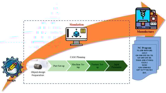
Figure 1.
Simulation stages.
3. Results and Discussion
Polygonal shaft modeling was carried out using CAD software according to the DIN-32711 P3G standard with d1 = 25 mm (diameter) and e = 0.80 mm (eccentric), so that d2 = 26.6 mm (outer diameter) (see Figure 2).
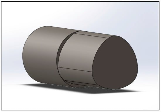
Figure 2.
Polygonal shaft modeling in CAD.
The first step in the simulation process is the selection of cutting tools and machining parameters; machine capability is a concern at this point. The machine’s holder condition must be taken into consideration when choosing a cutting tool, and the machining parameters must be changed to meet the requirements of the apparatus. There are two steps involved in creating P3G polygonal shafts: turning and milling. The selection of cutting tools and machining parameters can be seen in Table 2 and Table 3.
Table 2.
Cutting tool and machining parameters of turning process.
Table 3.
Cutting tool and machining parameters of milling process.
The P3G polygonal shaft is made through several machining processes according to the features contained in the shaft. The features in the simulation process for making polygonal profiles are the front outside diameter (OD) contour for roughing and finishing machining (see Figure 3 and Figure 4). This feature simulates adjusting the diameter of stock material to the diameter of the part/workpiece through the turning process.
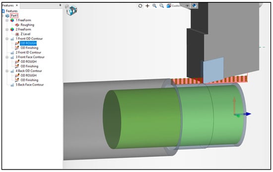
Figure 3.
Roughing simulation for front outside diameter feature.
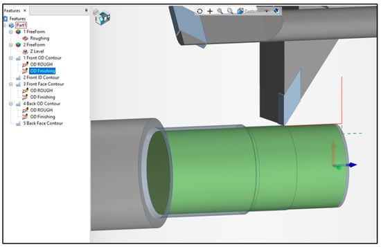
Figure 4.
Finishing simulation for front outside diameter feature.
The front face contour feature provides a simulation of the process of reducing face stock material to actual dimensions through roughing and finishing machining (see Figure 5 and Figure 6). The formation of the P3G profile is simulated using the free-form feature for roughing and the Z-level for finishing (see Figure 7 and Figure 8). The free-form feature is a turning milling process. At the same time, Z-level machining indicates a machining process parallel to the raw/stock material. At the end of the process, a complete polygonal shaft profile is formed (see Figure 9).
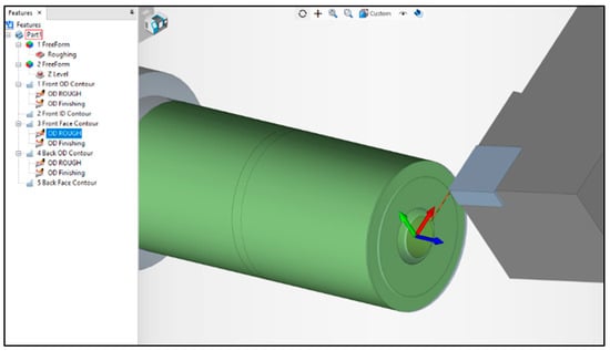
Figure 5.
Roughing simulation for facing feature.
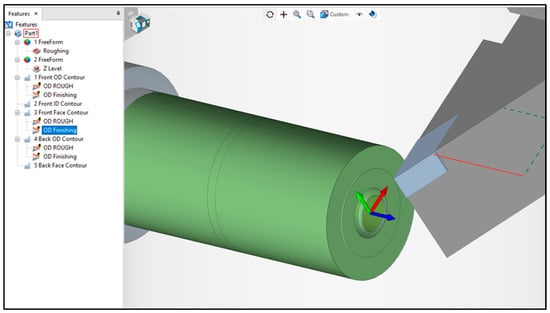
Figure 6.
Finishing simulation for facing feature.
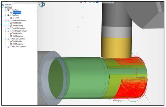
Figure 7.
Roughing simulation for free-form feature polygonal profile.
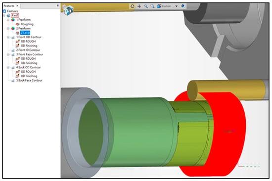
Figure 8.
Finishing simulation for Z-level polygonal profile.
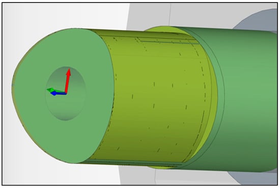
Figure 9.
Results of polygonal profile machining simulation.
G-code is produced through the simulation of the machining process with features, input of machining parameters, and tool type selection. This G-code is then used in the manufacturing process. Programming in G-code displays all of the commands used in CNC machining, including those for supporting operations like coolant orders as well as the main task of feeding the workpiece. Every block of a machining operation displays the G-code. Three primary machining operation blocks make up the polygonal profile simulation: the front OD contour feature, the front face contour feature, and the free-form feature, each with associated roughing and finishing procedures. An example of G-code simulation results is shown in Figure 10.
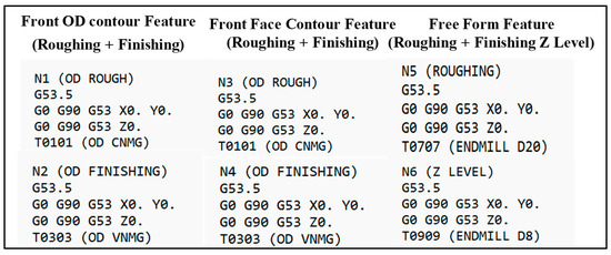
Figure 10.
Example of G-code block of machining process simulation results for each feature.
4. Conclusions
The main objective of this research was to use CAM ESPRIT software to simulate the process of creating polygonal profile shafts. A polygonal profile is a DIN 32711 P3G standard form whose diameter can be changed using CAD software to suit specific requirements. Three main features were used in the polygonal profile simulation: the front OD contour feature, the front face contour feature, and the free-form feature. These features were used to simulate the turning of the workpiece’s outside, the facing of the workpiece’s face, and the turning–milling process of the polygonal profile. The machining process is indicated for each feature by the parameter input and tool selection. According to the simulation results, these three primary features combine to form a polygonal profile and generate a G-code that can be used in the manufacturing procedure.
Author Contributions
Conceptualization, Y.A.H., M.F. and N.; methodology, M.F. and N.; software, N.A.R.; validation, M.F. and N.; formal analysis, M.F. and N.; investigation, M.F. and N.; resources, M.F. and N.; data curation, M.F. and N.; writing—original draft preparation, Y.A.H.; writing—review and editing, Y.A.H.; visualization, N.A.R.; supervision, M.F. and N.; project administration, U.H.; funding acquisition, U.H. All authors have read and agreed to the published version of the manuscript.
Funding
National Research and Innovation Agency Indonesia.
Institutional Review Board Statement
Not applicable.
Informed Consent Statement
Informed consent was obtained from all subjects involved in the study.
Data Availability Statement
Data are to be made available only via a request to the corresponding author. Data will be provided only after the acceptance and signature of a formal data-sharing agreement.
Conflicts of Interest
The authors declare no conflicts of interest.
References
- Dubovska, R.; Jambor, J.; Majerik, J. Implementation of CAD/CAM system CATIA V5 in simulation of CNC machining process. Procedia Eng. 2014, 69, 638–645. [Google Scholar] [CrossRef]
- Jambor, J. Quality of Production Process with CAD/CAM System Support. In DAAAM International Scientific Book 2012; DAAAM International Vienna: Vienna, Austria, 2012. [Google Scholar] [CrossRef]
- Majerik, J.; Jambor, J. Prismatic Milling Simulation Process and Cnc Programming in the Cad/Cam System Catia V5r20. In Annals & Proceedings of DAAAM International 2011; DAAAM International Vienna: Vienna, Austria, 2011; Volume 22, pp. 467–468. [Google Scholar]
- Rahmatullah, S.T.; Yohanes, I. Application of Virtual Manufacturing in Cnc Turning Operations. In Proceedings of the EnCon2010, 3rd Engineering Conference on Advancement in Mechanical and Manufacturing for Sustainable Environment, Serawak, Malaysia, 14–16 April 2010. [Google Scholar]
- Bhatta, R.; Reffeor, W. Experimental and Numerical Validation of DIN standard for polygonal shafts. In Proceedings of the 2016 ASEE North Central Section Conference, Mt Pleasant, MI, USA, 18–19 March 2016. [Google Scholar]
- Grobman, C. Fretting Fatigue of Shape Optimised Polygon-Shaft-Hub Connections. Ph.D. Thesis, Der Technischen Universitat Berlin, Berlin, Germany, 2007. [Google Scholar]
- Arndt, T.; Sellmeier, V.; Schulze, V. Model-based tool design for the manufacturing of hypocycloidal internal profiles by polygon turning. Procedia CIRP 2023, 117, 7–12. [Google Scholar] [CrossRef]
- Nur, L. Application Of Cnc Simulator For Cnc Machining Via Cad/Cam; Universiti Sains Malaysia: Penang, Malaysia, 2017. [Google Scholar]
- Zhu, X. Programming and machining of complex parts based on CATIA solid modeling. IOP Conf. Ser. Mater. Sci. Eng. 2017, 231, 012081. [Google Scholar] [CrossRef]
- Chang, K.-H. Virtual Machining. In e-Design; Elsevier: Amsterdam, The Netherlands, 2015; pp. 599–646. [Google Scholar] [CrossRef]
- Pan, L.; Guo, X.; Luan, Y.; Wang, H. Design and realization of cutting simulation function of digital twin system of CNC machine tool. Procedia Comput. Sci. 2021, 183, 261–266. [Google Scholar] [CrossRef]
- Valvo, E.L.; Licari, R.; Adornetto, A. CNC milling machine simulation in engineering education. Int. J. Online Eng. 2012, 8, 33–38. [Google Scholar] [CrossRef][Green Version]


Disclaimer/Publisher’s Note: The statements, opinions and data contained in all publications are solely those of the individual author(s) and contributor(s) and not of MDPI and/or the editor(s). MDPI and/or the editor(s) disclaim responsibility for any injury to people or property resulting from any ideas, methods, instructions or products referred to in the content. |
© 2024 by the authors. Licensee MDPI, Basel, Switzerland. This article is an open access article distributed under the terms and conditions of the Creative Commons Attribution (CC BY) license (https://creativecommons.org/licenses/by/4.0/).