
Controlled Sweat Removal in Performance Wear Using Electrically Activated Textiles †


Abstract
1. Introduction
2. Materials and Methods
2.1. Materials
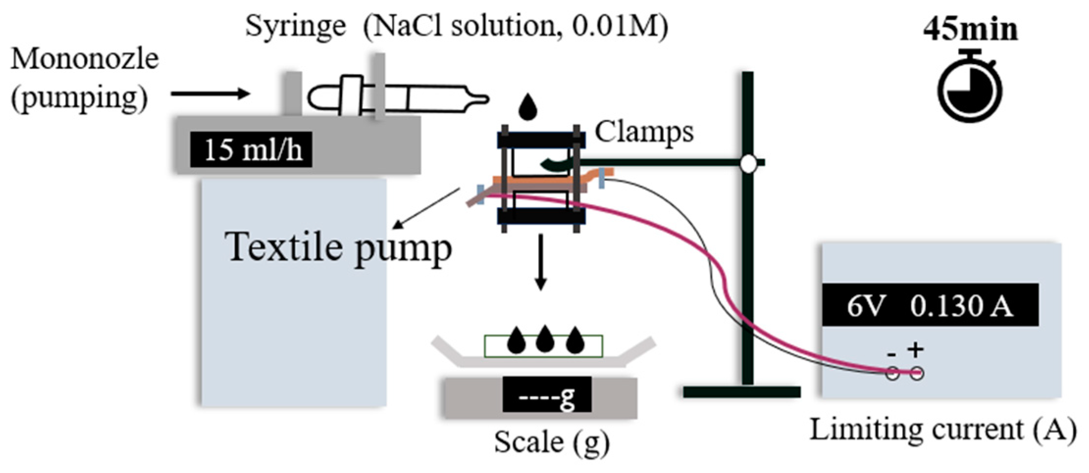
2.2. Flow Test Setup in the Direction of Gravity
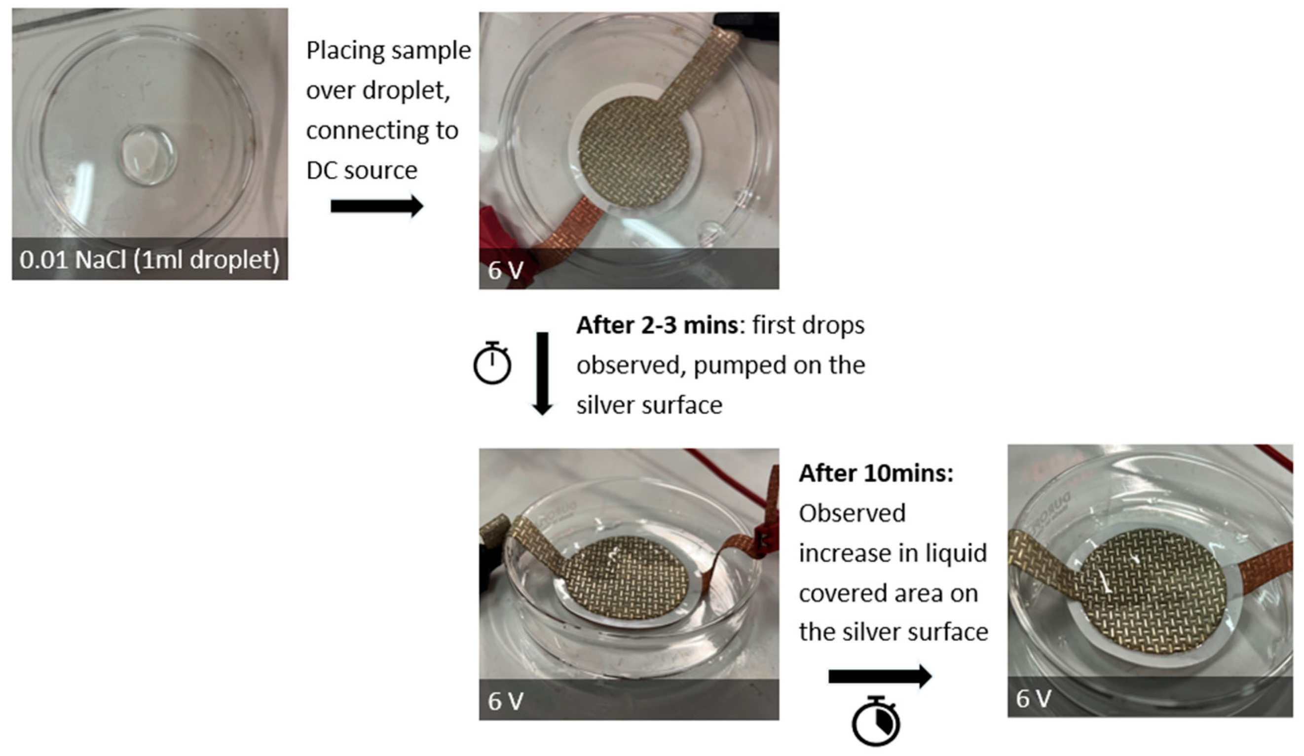
2.3. Flow Test Setup in the Direction against Gravity
3. Results
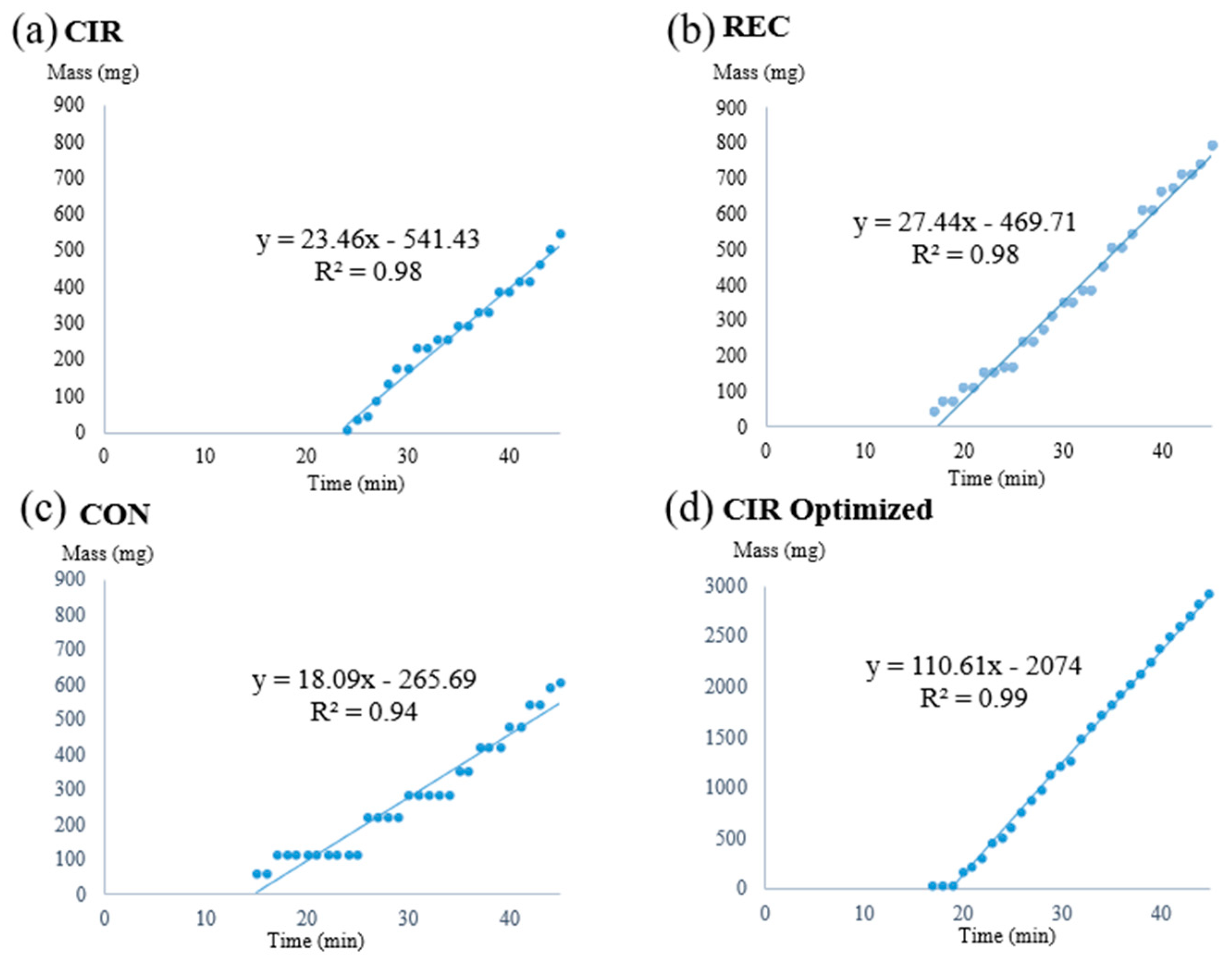
3.1. Flow Test in the Direction of Gravity
3.2. Influence of Gravity on Flow
4. Conclusions and Future Work
Author Contributions
Funding
Institutional Review Board Statement
Informed Consent Statement
Data Availability Statement
Conflicts of Interest
Appendix A

| Material Name | Function in the Electroosmotic Pump | Composition and Structure | Weight (g/m2) | Thickness (mm) | Surface Resistance (Ω/sq) | Average Surface Contact Angle (°) |
|---|---|---|---|---|---|---|
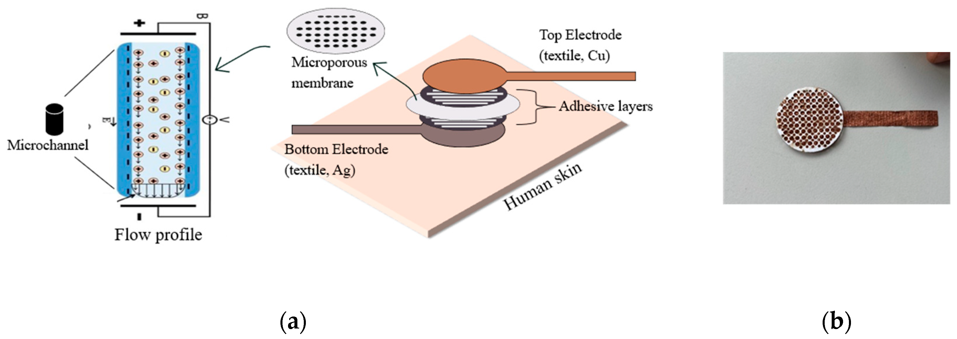
| Shieldex® Kiel + 30 | Top electrode (anode), thermally and electrically conductive. | Spun-bonded non-woven 100% Polyamide Nylon 6.6. Metal-plated with pure copper (48.65%). | 100 | 0.12 | <0.02 | 73.65 |
| Shieldex® Basel | Bottom electrode (cathode), thermally and electrically conductive. | Spun-bonded non-woven 100% Polyamide Nylon 6.6. Silver-coated, PA/Ag (75%/25%). | 38 | 0.25 | <1 | 87.11 |
| ipPORETM track-etched PC membrane | A microporous PC membrane with perpendicular microchannels between electrodes is needed to carry electrostatic charges between electrodes. | Hydrophilic microporous membrane with pore size of 0.0004 mm, porosity of 18.8%, and membrane diameter of 47 mm. | / | 0.025 | infinite | / |
| Vliesofix® Bondaweb 719 | Adhesive web to bind the electrodes and membrane together. | 100% PA | 70 | / | infinite | / |
| Sample Code | Initial Voltage (V) | Limiting Current (A) | NaCl-Water Solution (M) | Set Flow Rate of Solution (mL/h) | Initial NaCl Solution Drop * (mL) | Testing Time (min) |
|---|---|---|---|---|---|---|
| REC | 6 | 0.130 | 0.01 | 15 | 1 | 45 |
| CON | 6 | 0.130 | 0.01 | 15 | 1 | 45 |
| CIR | 6 | 0.130 | 0.01 | 15 | 1 | 45 |
| CIR Optimized | 6 | 0.150 | 0.01 | 15 | 1 | 45 |
Appendix B
Appendix B.1. Assembly of the Electroosmotic Pumps—Binding Procedure
References
- Chandrasekhar, P.; Pirgov, P.; Zay, B.J.; Lawrence, D.; Morefield, S.; Rittenhouse, T.; Clementi, S.; Truong, Q.; Greene, R. Electroosmotic Water Vapor Transport across Novel, Smart, Functionalized Conducting Polymer Microporous Membranes in Active Mode at Very High Rates, with Concomitant Chemical Warfare (CW) Agent Blocking. Adv. Mater. Phys. Chem. 2013, 3, 217–237. [Google Scholar] [CrossRef]
- Zhang, Y.; Tian, M.; Wang, L.; Zhao, H.; Qu, L. Flexible Janus Textile-Based Electroosmotic Pump for Large-Area Unidirectional Positive Water Transport. Adv. Mater. Interfaces 2020, 7, 1902133. [Google Scholar] [CrossRef]
- Bengtsson, K.; Robinson, N. A large-area, all-plastic, flexible electroosmotic pump. Microfluid. Nanofluidics. 2017, 21, 178. [Google Scholar] [CrossRef]
- Sreenath, S.; Suman, R.; Sayana, K.; Nayanthara, P.; Borle, N.G.; Verma, V.; Nagarale, R.K. Low-Voltage Nongassing Electroosmotic Pump and Infusion Device with Polyoxometalate-Encapsulated Carbon Nanotubes. Langmuir 2021, 37, 1563–1570. [Google Scholar] [CrossRef] [PubMed]
- Bengtsson, K.; Christoffersson, J.; Mandenius, C.F.; Robinson, N.D. A clip-on electroosmotic pump for oscillating flow in microfluidic cell culture devices. Microfluid. Nanofluidics. 2018, 22, 27. [Google Scholar] [CrossRef]
- Hu, J.S.; Chao, C.Y.H. Development of an Electroosmotic Pump-Driven Micro LiBr Absorption Heat Pump System for Controlling Microclimate in Protective Clothing: Feasibility Review and Role of the Pump. HVACR Res. 2008, 14, 467–487. [Google Scholar] [CrossRef]
- Law, K.-Y. Water–surface interactions and definitions for hydrophilicity, hydrophobicity and superhydrophobicity. Pure Appl. Chem. 2015, 87, 759–765. [Google Scholar] [CrossRef]
- Snyder, J.L.; Getpreecharsawas, J.; Fang, D.Z.; Gaborski, T.R.; Striemer, C.C.; Fauchet, P.M.; Borkholder, D.A.; McGrath, J.L. High-performance, low-voltage electroosmotic pumps with molecularly thin silicon nanomembranes. Proc. Natl. Acad. Sci. USA 2013, 110, 18425–18430. [Google Scholar] [CrossRef] [PubMed]
- Tian, S.; Zhang, W.; Shi, J.; Guo, Z.; Li, M. A Performance-enhanced Electroosmotic Pump with Track-etched Polycarbonate Membrane by Allylhydridopolycarbosilane Coating. Anal. Sci. Int. J. Jpn. Soc. Anal. Chem. 2020, 36, 953–957. [Google Scholar] [CrossRef] [PubMed]
- Ai, Y.; Yalcin, S.E.; Gu, D.; Baysal, O.; Baumgart, H.; Qian, S.; Beskok, A. A low-voltage nano-porous electroosmotic pump. J. Colloid. Interface Sci. 2010, 350, 465–470. [Google Scholar] [CrossRef] [PubMed]
- Wu, X.; Ramiah Rajasekaran, P.; Martin, C.R. An Alternating Current Electroosmotic Pump Based on Conical Nanopore Membranes. ACS Nano 2016, 10, 4637–4643. [Google Scholar] [CrossRef] [PubMed]
- Kofler, M.; Lenninger, M.; Mayer, G.; Neuwirt, H.; Grimm, M.; Bechtold, T. Multi-chamber electroosmosis using textile reinforced agar membranes—A promising concept for the future of hemodialysis. Carbohydr. Polym. 2016, 136, 81–86. [Google Scholar] [CrossRef]
- Manoharan, K.; Bhattacharya, S. Superhydrophobic surfaces review: Functional application, fabrication techniques and limitations. J. Micromanuf. 2019, 2, 59–78. [Google Scholar] [CrossRef]
| Sample Code | Code Meaning | Perforated Shapes | Total Surface Area (cm2) * | Active Surface Area ** (cm2) |
|---|---|---|---|---|
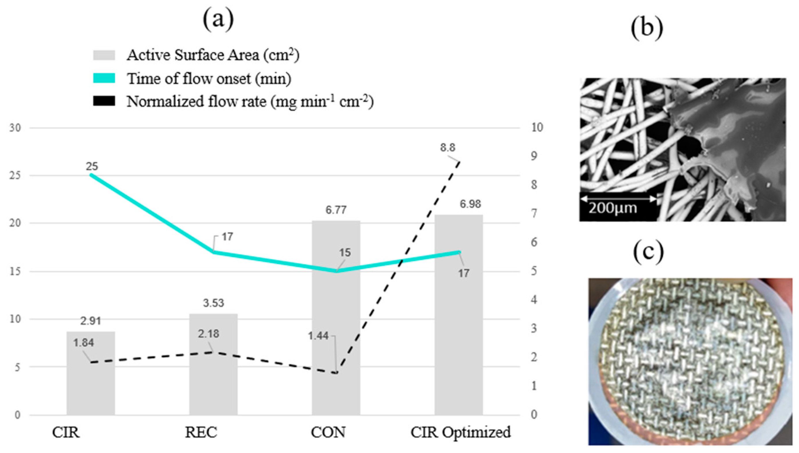
| REC | Rectangle |  | 12.56 | 3.53 |
| CON | Conical | 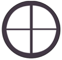 | 12.56 | 6.77 |
| CIR | Circular | 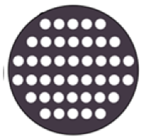 | 12.56 | 2.91 |
| CIR Optimized | Circular, optimized (high surface area) | 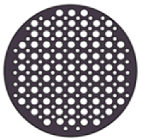 | 12.56 | 6.98 |
Disclaimer/Publisher’s Note: The statements, opinions and data contained in all publications are solely those of the individual author(s) and contributor(s) and not of MDPI and/or the editor(s). MDPI and/or the editor(s) disclaim responsibility for any injury to people or property resulting from any ideas, methods, instructions or products referred to in the content. |
© 2024 by the authors. Licensee MDPI, Basel, Switzerland. This article is an open access article distributed under the terms and conditions of the Creative Commons Attribution (CC BY) license (https://creativecommons.org/licenses/by/4.0/).
Share and Cite
Georgievska, M.; Moeed, A.; Malengier, B.; Van Langenhove, L. Controlled Sweat Removal in Performance Wear Using Electrically Activated Textiles. Eng. Proc. 2023, 52, 28. https://doi.org/10.3390/engproc2023052028
Georgievska M, Moeed A, Malengier B, Van Langenhove L. Controlled Sweat Removal in Performance Wear Using Electrically Activated Textiles. Engineering Proceedings. 2023; 52(1):28. https://doi.org/10.3390/engproc2023052028
Chicago/Turabian StyleGeorgievska, Magdalena, Abdul Moeed, Benny Malengier, and Lieva Van Langenhove. 2023. "Controlled Sweat Removal in Performance Wear Using Electrically Activated Textiles" Engineering Proceedings 52, no. 1: 28. https://doi.org/10.3390/engproc2023052028
APA StyleGeorgievska, M., Moeed, A., Malengier, B., & Van Langenhove, L. (2023). Controlled Sweat Removal in Performance Wear Using Electrically Activated Textiles. Engineering Proceedings, 52(1), 28. https://doi.org/10.3390/engproc2023052028