1. Introduction
A detailed analysis of scientific and technical information on Stirling engines (SE) from a number of foreign countries [
1,
2,
3,
4,
5] showed that the most important elements in the development of this promising engine are the main heat exchangers of the internal circuit [
6,
7,
8,
9,
10] and efficient heat supply in the external circuit [
11,
12].
The nonstationary cyclic working fluid flow regime causes major difficulties in designing heat exchangers for Stirling engines. In most cases, the operation of conventional industrial heat exchangers is considered under a steady state flow regime with slowly changing parameters. A contrasting view is observed in Stirling engines, where the flow mode of the working fluid is nonstationary. This mode is characterized by significant changes in pressure, density and flow rate, the direction of which changes twice per cycle. These circumstances significantly complicate the design of regenerators and other heat exchangers for Stirling engines [
13,
14].
In engineering practice, of greatest interest is not the definition of instantaneous changes in parameters in the coolant flow, but the definition of the average temperature and pressure in the recuperative heat exchanger (RHE) of the engines with external heat supply (EEHS), the average heat flux and the average wall temperature, i.e., of interest is the estimation of the average boundary conditions for heat exchangers. Therefore, as a real method of calculation, the one-dimensional method of describing heat exchange and hydrodynamics processes using average heat and resistance coefficients is widely used [
7,
15,
16,
17]. It is known that the criterial equations of time-averaged convective heat transfer and hydrodynamics of a pulsating fluid flow with variable physical properties can be written as:
By estimating the values and combining a number of similarity criteria for heat transfer conditions and hydrodynamics in the RHE of the EEHS, two dimensionless parameters were revealed that determine the effect of nonstationarity on these processes: EC is the Eckert criterion and is the dimensionless frequency parameter , where d is the diameter, is the pulsation frequency, is the kinematic viscosity.
Calculated estimation of the variation range of in RHE of the EEHS, in the area of practically interesting geometrical and operating parameters of the engine was established that varies in the range 1.5−10.
But a theoretical assessment of the influence of EC and on the processes in question presents considerable difficulties.
Analysis and generalization of experimental works on the stability of pulsating reverse flow, taking into account the features of the geometric and regime parameters of the RHE of the EEHS, makes it possible to conclude that there is a turbulent regime in the flow of the working fluid in the range of changes in the flow rate according to the Reynolds number . This, in turn, leads to an increase in the intensity of heat transfer and hydraulic resistance in RHE within the specified Re range.
In addition, as experimental data show, the influence of the dimensionless frequency parameter on the nature of the change in the heat and hydraulic characteristics of heat exchangers at can be neglected. At the same time, a significant decrease in the value of () corresponds to a sharp increase in the stability of the flow of the working fluid and, as a consequence, a decrease in the intensity of heat transfer. Comparison of experimental data obtained by other researchers with the results of calculations using criterial dependencies for stationary flows made it possible to propose estimates for heat transfer at . In particular, at > 1, the heat transfer in the specified Re range can be described by the equation of turbulent heat transfer, and at , the heat transfer intensity decreases, approaching the quasi-stationary state.
It is shown that the effect of the EC criterion on the time-averaged heat transfer in the ideal case, with symmetry of the thermodynamic processes of expansion and contraction in RHE EEHS, is the negligible. And in real conditions, this effect can be evaluated by conducting experiments at different pressure coefficients characterizing the degree of pressure increase in the working chamber of the engine. The pressure coefficient reflects the influence of the geometric and kinematic parameters of the engine, as well as the temperature regime of its operation, on the pattern of pressure changes.
Evaluation of the influence of the modified bio criterion value in RHE EEHS allows us to refer the interaction of the pulsating reverse flow of the working fluid with the heat exchange surface to the high-frequency range; i.e., in RHE, the wall temperatures T
W can fluctuate within insignificant limits, and therefore these fluctuations can be neglected. The paper [
6] shows that the combination of this phenomenon with the reversibility of the flow of the working fluid provides a significant non-uniformity in the distribution of the average time-integrated wall temperature along the RHE length, which must be taken into account when calculating engine heat exchangers. It has been established that the uneven distribution of the wall temperature along the length of the RHE depends on the scheme of movement of heat carriers, on the ratio of the intensity of heat transfer in the inner and outer circuits and reduces the efficiency of the RHE EEHS.
Correction factors defining the degree of heat exchangers efficiency reduction are determined from consideration of the thermal balance equation of the RHE EEHS wall. The comparative analysis showed that the calculation methodology of the RHE EEHS leads to the calculation scheme of heat exchangers with complex patterns of coolant motion under stationary conditions. In this case, it should be taken into account that the heat exchange surface of the RHE EEHS is two times smaller than in the indicated schemes. It is also necessary to take into account the decrease in efficiency due to the reversibility of the working fluid movement and the underregeneration of heat in the regenerator.
It is known that the intensification of heat transfer in a stationary flow in the region of the transitional flow regime is determined by two phenomena. The first is the effect of turbulators on the reduction of the critical number Recr. The second is artificial turbulence of the flow with a weak turbulent structure. Both phenomena depend significantly on the height of the turbulators and a noticeable effect can be obtained only at .
The additional reduction of Recr in the pulsating reverse flow intensifies both of these phenomena. Thus, the effects of heat transfer intensification by turbulators of the two-dimensional roughness type in the laminar and transient regimes in RHE EEHS, as opposed to stationary flows, are possible and significant both at , as well as at a developed turbulent flow. In addition, these effects suggest the validity of heat transfer patterns for surfaces with turbulators in the region of developed turbulent flow and for flow regions in the RHE EEHS in the range .
A reasonable method of comparing heat transfer surfaces is necessary for proper selection. However, traditional methods for evaluating the efficiency of heat exchange intensification cannot be used for RHE EEHS, since the design dimensions and operation parameters of the heat exchanger internal circuit have an influence on the engine operating process.
A method of comparative evaluation of heat exchange surfaces efficiency under conditions of their operation in the EEHS system is proposed, based on comparison of surfaces under similar thermodynamic conditions. In this case, the comparative criterion of energy efficiency shows how many times less power loss for pumping of the working fluid in the HE with the studied surface, as compared to the initial one under the same thermodynamic conditions.
2. Experimental Setup and Technique
The description of the experimental setup simulating the operating conditions of the RHE in the EEHS system, the experimental sections, the measuring system and the methodology for conducting experiments, processing the results and estimating the errors in determining the basic quantities are given below.
In order to obtain experimental characteristics of heat transfer and hydrodynamics of the working fluid flows in the heat exchange circuits of the EEHS, a simulating installation was created. This makes it possible to study the modules or individual elements of the heat exchange circuits under conditions similar to the operation of these elements in the EEHS, with a power of up to 100 kW.
The operating principle of the installation is to create periodic perturbations of the working fluid flow in the heat exchangers inlet sections as a result of conversion of the dynamic flow head into the potential energy of the pressure.
The experiments were carried out according to the scheme of
Figure 1 of a one-sided entry of the working fluid from the ramp of cylinders 7 into the heater 19, heated by an electric current, the accumulation of the working fluid in volume 24 after passing through the heater and subsequent discharge of the battery. Coolers 4 and 27 and regenerators 3 and 28 are installed on both sides of the heater to reduce the working fluid temperature in front of the spool I and create conditions at the inlets simulating the boundary conditions on the engine. Pulsations of pressure and flow rate were created by periodically blocking the air line by a rotating perforated disk in spool 1. To vary the nature of the change in pressure and flow rates, the perforated disks were made replaceable, with different profiles of the inlet and outlet channels.
The experimental sections are stainless steel tubes (19) of diameters 5 × 0.375 mm and I2 × 2 mm. Artificial two-dimensional roughness in the 5 × 0.375 mm pipes was created by mechanical (discrete and spiral) rolling. The roughness was a set of semicircular transverse protrusions h = 0.1, 0.15 and 0.2 mm high, located on the heating surface at a distance S = 3 mm from each other. A chromel wire turbulator, with a diameter of 0.2 mm and a spacing of S = 3 mm on the inner surface of the tube of 5 × 0.375 mm, was also used. The heat flow in the investigated tubes was determined by the current and the active resistance of the section. The time-averaged temperature of the flow at the inlet to the heater, as well as in the accumulating volume, was measured by (K) (Cromel-alumel) thermocouples 0.1 mm in diameter. The wall temperature was measured at five or six points along the length with (L) (Chromel-copel) thermocouples 0.2 mm in diameter. To measure the instantaneous temperature of the flow Tf, resistance thermometers with a sensitive element made of tungsten–rhenium wire with a diameter of 0.015 mm were used. Instantaneous pressures were recorded using inductive pressure sensors (IPS-21). Pressure drops were measured by differential sensors DMI-1. Signals from temperature and pressure sensors were amplified using TS-5 strain gauge station and an ID-2I indicator and output to an H-115 loop oscilloscope. Electromotive forces (emf) of thermocouples were recorded on KSP-4 potentiometers.
The mass flow rate of the working fluid in the stationary mode was measured by the pressure drop on the calibration washer connected via a pipeline to the accumulating volume 24, with the plug 26 removed. The instantaneous and average values of the flow rates through the heater in non-stationary modes were obtained by the indirect method widely used in the practice of EEHS, i.e., by using the ideal gas equation of state to calculate the specified parameters from known temperature, pressure and volume curves.
The heat transfer coefficient averaged over time and along the length of the heater was determined by the arithmetic mean temperature difference, and the average resistance coefficient was determined by the Darcy–Weisbach formula. The flow temperature averaged along the length of the heater was taken as the control temperature, and the internal diameter of the tube was taken as the control size. The estimated heat flux was assumed to be constant along the entire heating surface.
The accuracy of the estimated determination of the working fluid time–average consumption was determined using a thermal anemometer without temperature compensation during cold purges of the experimental section. In general, the organization of measurements of primary values made it possible to calculate the experimental values of the heat transfer coefficients and resistance in a stationary flow with an error within 2–5%, and in a non-stationary pulsating reverse flow—within 2%.
3. Discussion of Experimental Study Results
It was found that the laws of pressure and temperature variations at the heater ends, obtained on the simulator, are close to the data obtained on the engine. Comparison of the character of changes in the specified parameters by disc (motor shaft) rotation angle
, for various heaters at tests with two spool discs with different profiles of inlet and outlet channels, shows a qualitatively similar picture (
Figure 2). A clear trend of approaching the pressure curves P on the model to the data on the engine indicates the possibility and quantitative modeling
of the engine with the proper selection of design elements and regimes. The unit makes it possible to obtain different values of pressure coefficient (
), in a wide range of disc rotation speed and pressure of the working fluid. The unit design provides for the possibility to increase the maximum pressure up to 10 MPa and the maximum temperature up to 1000 K.
Simulating unit, working fluid—air: 1—ω = 15 s
−1, δ = 0.259, 1—disk; 2—ω =14.9 s
−1, δ = 0.227, 2—disk; 3—ω = 15.6 s
−1, δ = 0.217, 2—disk is wire turbulator, S/h =10. A and B are the inlet sections of the heater (
Figure 1). Engine, working fluid—helium: 4—ω = 10 s
−1, δ = 0.19, phase angle 120°, EH and RH are the inlet sections of the heater from the side of the chamber and the regenerator, P
c—pressure in the cold chamber.
Experimental studies of heat transfer in a stationary flow of the working fluid (air) at
> 104 confirmed the well-known dependence for the turbulent flow regime:
where
hat
.
In experiments on heat transfer and hydrodynamics of a pulsating reverse flow of the working fluid, the main parameters varied within the following limits: time-averaged Reynolds number from 103 to 2.6 × 10⁴, the temperature ratio , the flow pulsation frequency , the pressure coefficient and the L/d ratio, taking into account the initial stabilizing section 50–120.
The results of experiments carried out at Re > 104 show that to calculate the nonstationary heat transfer Nu in the RHE engine in the turbulent flow region, the stationary heat transfer Equation (1) can be used, which coincides with the data of other authors for the RHE of gas-cooling machines operating on the Stirling cycle. Comparison of dependences of the form Nu = f(Re) obtained for stationary and pulsating reverse flows of the working fluid made it possible to determine the presence of a turbulent regime in the range of change and thereby confirm the results of theoretical analysis.
The analysis of the results made it possible to confirm the absence of the influence of the frequency and the dimensionless frequency parameter on the indicated characteristics. This was also indirectly confirmed by the data on the distribution of the wall temperature along the RHE length. An analysis of data on heat transfer depending on the pressure coefficient did not reveal a noticeable effect of the latter. As a result of summarizing the experimental data on heat transfer in a pulsating reverse flow of the working fluid, it was found that heat transfer (Nu) in the range of variation within the accuracy of the experiment can be described by Equation (1). Experiments on revealing the influence of radius of curvature R on heat exchange in curved pipes in two experimental sections (d/R = 0.0567; 0.085) have shown that in practical calculations of the RHE SE, it is acceptable to use equations for stationary flow of heat carriers.
As a result of the generalization of experimental data on the study of hydraulic characteristics, the following equation was obtained:
Figure 2 shows experimental data on heat transfer in stationary and pulsating reverse flows of the working fluid, and data on the pressure drop at S/h = 15 for the studied types of two-dimensional roughness, as well as thermal–hydraulic characteristics of the discretely rolled pipes at S/h =15; 20; 30. Thus, the possibility of increasing the intensity of heat transfer during artificial flow turbulization in the reverse-pulsating flow of the working fluid in the RHE EEHS is shown. A comparison of the data obtained in different experimental sections at S/h = 15 showed that the data on heat transfer essentially coincided with each other within a scatter of experimental points equal to 15%, with Nu and in the range of variation
practically coinciding with the stationary Nu
st,sh, and in the region
, Nu
sh is significantly higher than Nu
st,sh. In terms of the pressure drop, discretely rolled pipes have the best characteristics.
As a result of the generalization of experimental data on heat transfer Nu
sh in rough pipes, it has been established that the following equation
can be recommended for its description in the entire studied range of Re. The data on resistance are summarized as dependence:
In the turbulent region, the data are clustered around curves obtained by interpolating the other researchers experiment results within the experimental error.
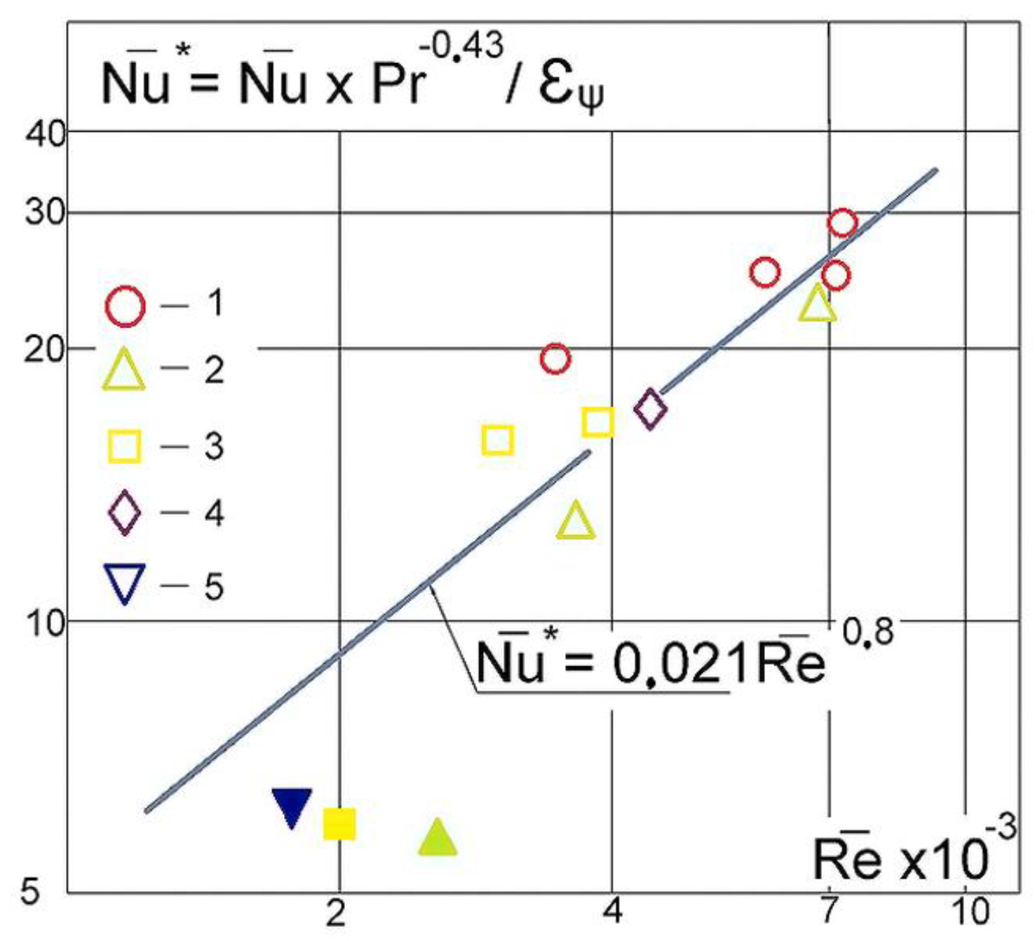
The results of the comparison of experimental data on heat transfer in tubular RHE, obtained from the simulator, with data obtained on an engine, and recommendations for choosing the height and spacing of the protrusions in discretely rolled tubes have been presented. To justify the reliability of the experimental heat exchange data obtained on the simulation unit, they were compared with the results obtained on the real engine, as shown in
Figure 3. Analysis of the data obtained on the cooler of the hot model of EEHS (
Figure 3) confirmed the validity of the theoretical assumptions of the present work and the experimentally established patterns of heat transfer in the RHE EEHS. Based on the analysis of the characteristics of discretely rolled pipes using the developed method for comparative evaluation of heat transfer intensification, it is recommended to use the ratios
in RHE EEHS as the most effective.
Working fluid—helium, coolant: 1— = 5 MPa, 2— = 4 MPa, ; Data of other researchers: working fluid—nitrogen, = 0.8 MPa; 4—coolant, ; 5—heater, ; light dots correspond to ε > 1, black dots correspond to ε ≤ 1.
4. Conclusions
The possibility of modeling the operating conditions of Stirling engine recuperative heat exchangers in a wide range of working process parameters has been shown.
The obtained criterion dependencies should be used to calculate the average heat transfer coefficients and hydraulic resistance of gas in recuperative heat exchanger operating in the Stirling engine system in the ranges of , , .
The possibility of heat transfer intensification in the reverse pulsating flow of the working fluid in Stirling engine recuperative heat exchangers has been shown. In the ranges of Re change, is recommended as the most effective.


 ,
, 
