Proceeding Paper

The Influence of Adding Silica Fluoroalkylsilane on the Morphology, Mechanical, and Corrosion Resistance Properties of Sol-Gel Derived Coatings †

1
Mechanical and Energy Department, The Libyan Academy, Tripoli P.O. Box 79031, Libya
2
Student Support Services Department, The University of Sheffield, Sheffield S10 2TG, UK
3
Materials and Engineering Research Institute (MERI), Sheffield Hallam University, Sheffield S1 1WB, UK
4
North Africa International Center for Research on Serums, Vaccines and Genetic Diseases, Zawia P.O. Box 80045, Libya
5
Biomolecular Sciences Research Centre (BMRC), Sheffield Hallam University, Sheffield S1 1WB, UK
*
Author to whom correspondence should be addressed.
Presented at the 4th International Electronic Conference on Applied Sciences, 27 October–10 November 2023; Available online: https://asec2023.sciforum.net/.
Eng. Proc. 2023, 56(1), 98; https://doi.org/10.3390/ASEC2023-15380
Published: 26 October 2023
(This article belongs to the Proceedings of The 4th International Electronic Conference on Applied Sciences)

Abstract

:
Sol-gel-derived coatings’ corrosion resistance and mechanical properties have been studied frequently in the literature individually. However, there is a limitation in the studies that consider both mutually, as is common in all sol-gel hybrid coatings, for instance, mechanical failures such as cracks that influence the mechanical durability of coatings as well as their corrosion resistance. Therefore, this research will study the impact of adding fluoroalkylsilane (FAS) to silica-based sol-gel on its mechanical properties by using atomic force microscopy (AFM) nanoindentation, cross-cut adhesion, microhardness, and water contact angle, in line with a short investigation of corrosion resistance using electrochemical coating to test for the new modified coatings, which will be discussed. The results show that the new modified coating with fluoroalkylsilane was more flexible and could produce mechanical and corrosion protection stability, enhancing the hydrophobicity of the new surface, which is essential within the coating industry.

1. Introduction

Corrosion is one of the global problems affecting assets as it creates metal oxides and destroys the mechanical stiffness of construction parts, which could lead to significant failure [1]. Many techniques mitigate this effect. One of these good techniques involves using hybrid sol-gel coating as it mixes organic and inorganic preservative coatings and does not need a very thick coating, which could provide corrosion protection in a few micrometres. The sol-gel can generate films of inorganic or hybrid materials via the hydrolysis and condensation of metallic alkoxide precursors. Numerous areas, including optics, electronics, catalysis, and corrosion prevention, have been interested in them. Coatings made from silica using sol-gel polymerizing technology have shown promise in protecting light metals against corrosion in aircraft and marine settings due to their high chemical stability and low corrosion rates. However, the adherence and durability might be compromised by the low hydrophobicity of coatings based on silica. Surface roughening and the addition of fluoroalkylsilanes (FASs) into the sol-gel network are only some of the methods to develop the increase of silica-based coatings’ water-repellence. These fluorinated-derived alkylsilanes (FASs) are organic–inorganic hybrid compounds that react with the sol-gel precursors. They can provide low surface energy and strong compatibility with the sol-gel matrix to create superhydrophobic coatings with high contact and low slide angles. However, the coating’s transparency, mechanical strength, and corrosion resistance may all be affected by the distribution and concentration of FASs in the sol-gel network. Optimizing their synthesis circumstances and parameters is necessary to obtain the required properties out of FAS-modified sol-gel coatings [2,3,4,5].
According to prior studies, it has been shown that coatings produced from silica using sol-gel polymerization technology have the capability to be used in aircraft and marine environments for safeguarding light metals from corrosion while also demonstrating exceptional chemical stability [6]. Furthermore, this approach represents an ecologically sound technical trajectory for producing surface coatings, exhibiting the considerable potential to supplant deleterious pre-treatment coatings such as conventional chromate coatings. Our earlier research developed hydrophobicity to enhance the corrosion resistance of our silica-based sol-gel on aluminium 2024-T3 alloy sintered at 80 °C. This novel silica-based sol-gel coating was created by introducing 1H,1H,2H,2H-perfluorodecyltriethoxysilane (FAS) to the base sol-gel system of triethoxymethylsilane (MTMS) and tetraethylorthosilicatesilane (TEOS) precursors and by strengthening it with a polydimethylsiloxane polymer [7]. This study is considered as continued work in the investigation of the effect of adding FAS to the coating’s thin film on its general mechanical and corrosion properties.

2. Materials, Methodology, and Characterization

2.1. Sol-Gel Preparation

Starting by mixing both TEOS and MTMS precursors and isopropanol (all from Sigma-Aldrich, Merck Group, Gillingham, UK) to (DI) water dropwise, maintaining a molar ratio of 18:14:17:220. Then, a solution of 12-mole % polydimethylsiloxane (PDMS) polymer was added to enhance the sol-gel consistency. Then, the formula was stirred with dropwise nitric acid as a catalytic agent for the last 24 h of hydrolysis and condensation polymerization and was used as the base coating [7]. After that, the base sol-gel formula was then improved by being hybridized with the fluorinated FAS from Sigma-Aldrich by adding 1.5 vol.% to create a FAS-modified sol-gel formula.

2.2. Sample Preparation

With Q-Lab, the aluminium alloy AA2024-T3 Q-panels (102 mm × 1.6 mm × 25 mm) were used as examining substrates. The received aluminium plates were cleaned using a commercial high pH surface-active agent cleaner, followed by rinsing with DI water and acetone to remove organic deposits. After this process, sol-gel was sprayed over the aluminium substrates. It was applied in three passes to achieve sample homogeneity in the coating thickness at about 20 μm. These samples were annealed for 4 h at 80 °C [8,9].

2.3. Mechanical and Corrosion Testing

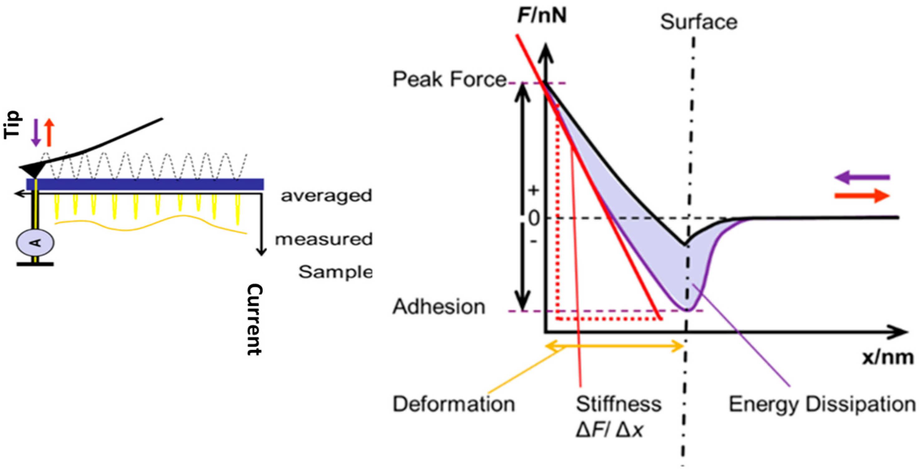
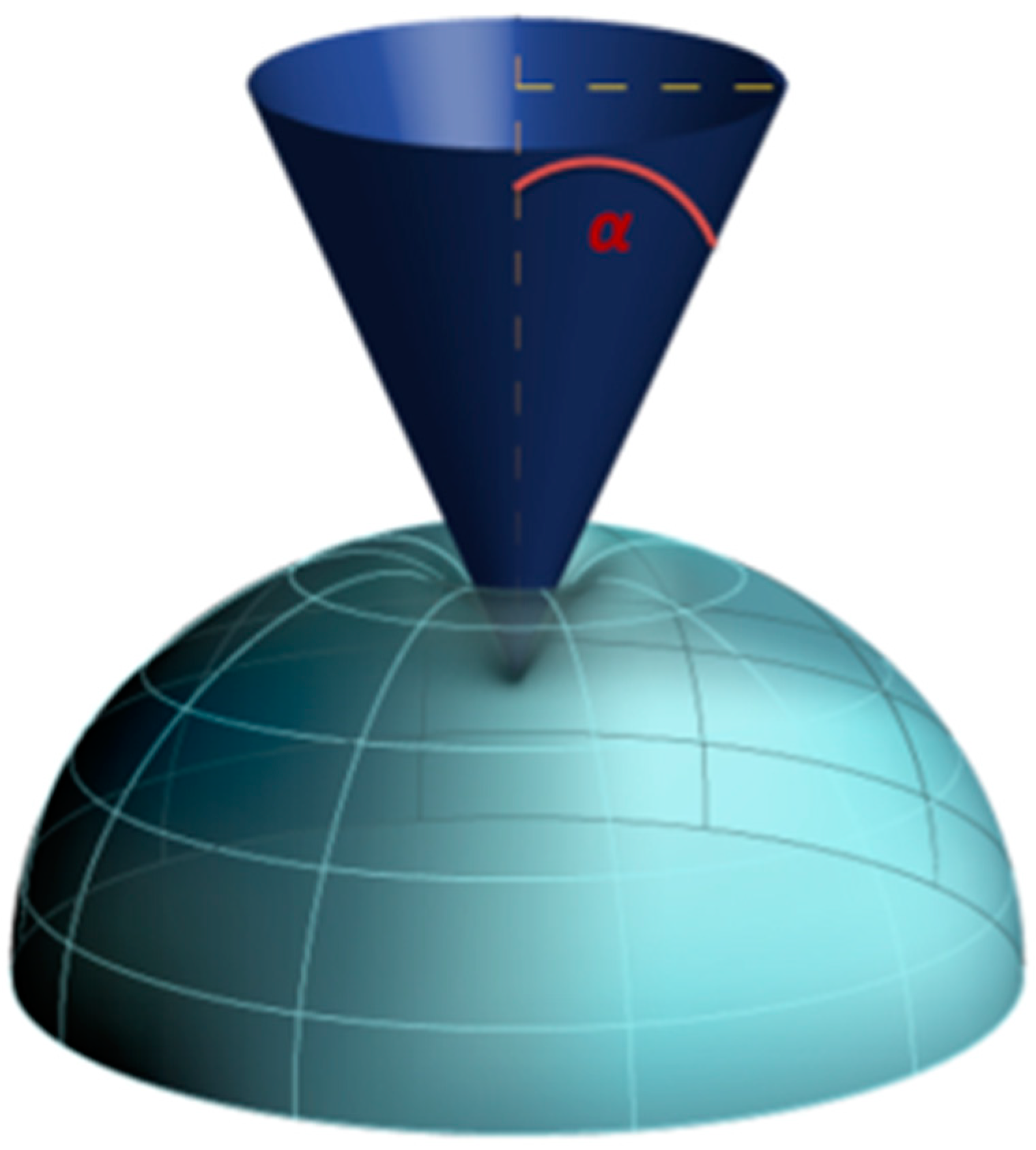
2.3.1. Atomic Force Microscopy Indentation

The Atomic force microscopy (AFM) instrument used in this investigation was the Bruker multi-mode eight, which operates in contact and tapping mode and has nanoindentation capabilities. The measurements were conducted at a controlled ambient temperature of 20 °C and humidity of 40%. The AFM method used in this study included the utilization of the contact-tapping mode. The acronym “RTESPA-300” refers to a specific system or technology, but rectangular probes coated with a layer of antimony-doped silicon (Si) and an additional coating of the aluminium reflective film were used in this study. These probes were characterized by a cantilever length of 125 μm, a force spring constant (Kc) of 40 N/m, and a resonant frequency of 300 kHz.

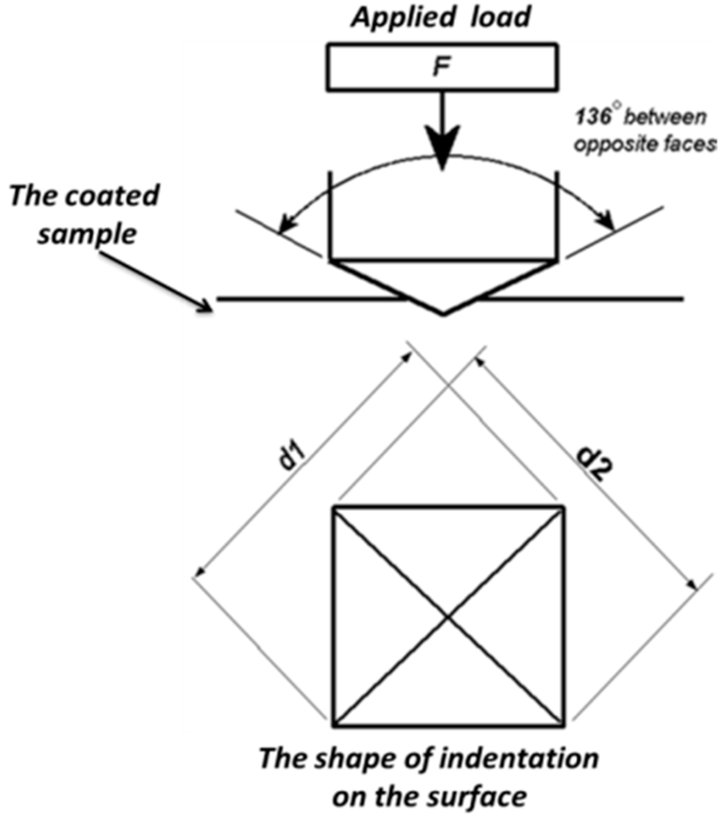
2.3.2. Microhardness Testing

This study measured the microhardness using the DURAMIN-40 automated micro/macro-hardness machine tester, (Struers Ltd., Rotherham, UK). The testing device has a range of loads from 1 g force load to 62.5 kg force load. Microhardness testing is a method that quantitatively assesses a material’s resistance to indentation by subjecting it to a small force, typically less than 1 kg force load, using a sharp indenter, depending on the shape of the indenter and the intended outcome. This study used a Vickers indenter and applied a 10 to 50 gf load.

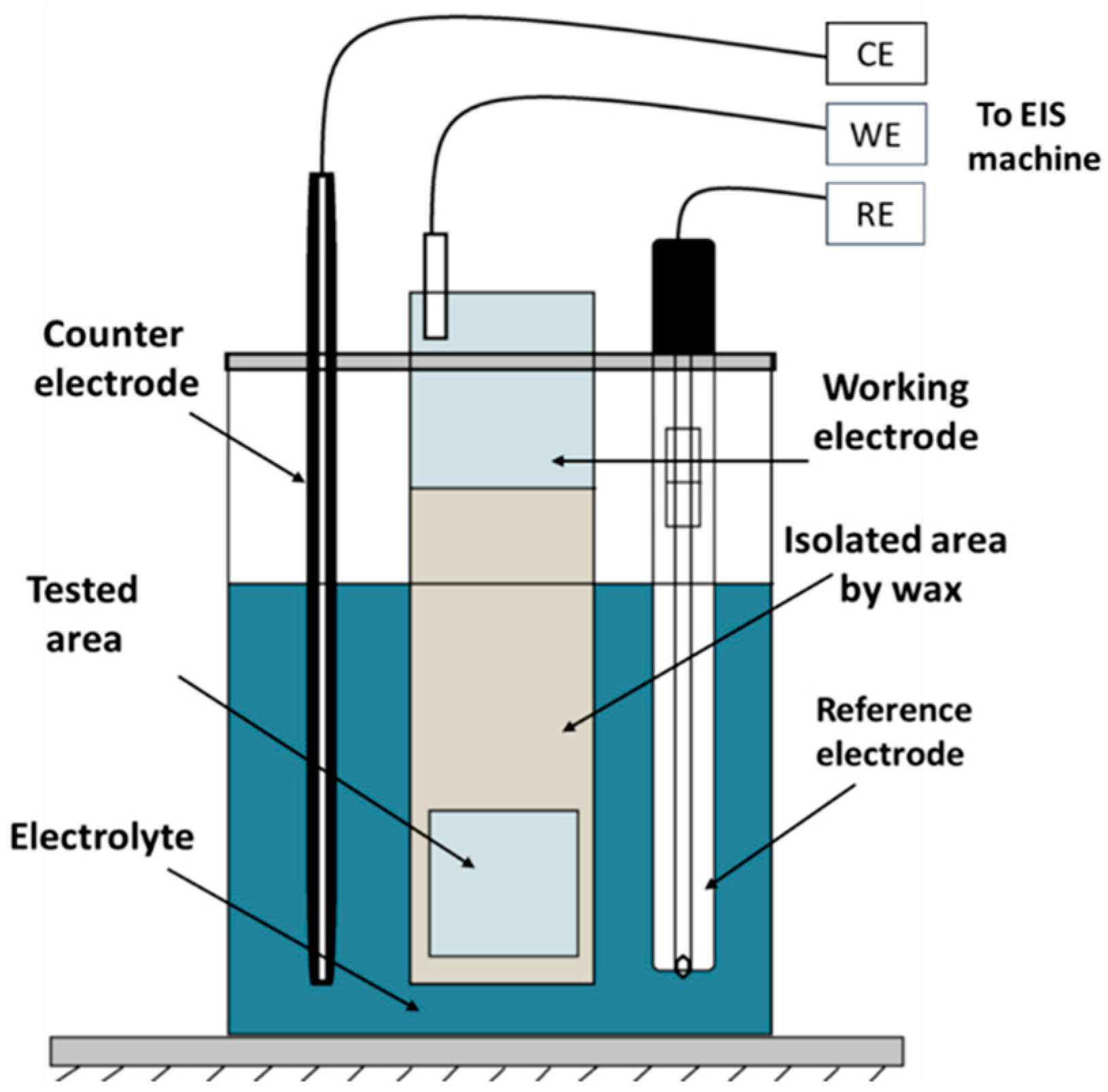
2.3.3. Electrochemical Testing (EIS.)

Figure 1 illustrates the electrochemical testing cell used on the PARSTAT 2273 EIS machine (AMETEK Scientific Instruments, Hampshire, UK). It was used to assess the corrosion resistance behaviour of both coated samples. The EIS test specimens were concealed using a mixture of beeswax and colophony resin, with deliberate exposure of the centre in one cm2. The experiments were conducted under ambient conditions, namely, at a temperature of 25 °C with a tolerance of ±2 °C, using a 3.5% weight/volume concentration of sodium chloride solution that was aerated. Prior to conducting the EIS test, the electrode potential of the solution was observed and recorded for about one hour until it reached a state of stability. Subsequently, the sample under testing measurements were gathered within the frequency limits between 100 kHz to 10 MHz, and the AC RMS sinusoidal value employed during the measurements was 10 mV.

3. Results and Discussions

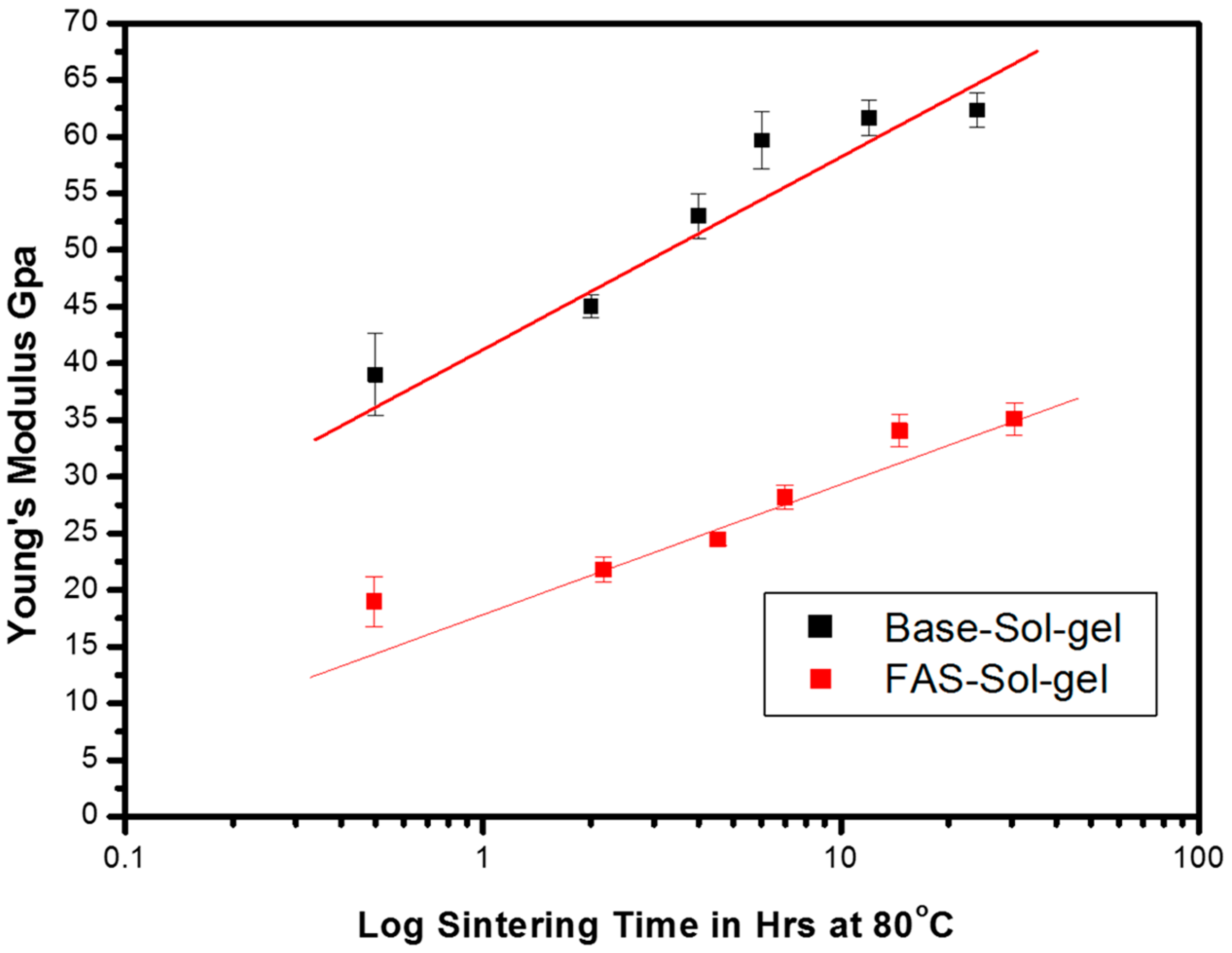
3.1. The Influence of FAS on Mechanical Properties of the Sol-Gel Film

Indentation using the AFM may be used to understand material deformation and failure and to build new materials with improved performance and usefulness. Different contact mechanics models offer pros and cons depending on the application and environment. Initially, AFM investigated the attractive forces between the surfaces of a sample and an AFM tip. This technique allowed for the scanning of the topography of materials at a nanoscale level of precision, with particular emphasis on identifying phase variations in specific regions [10]. After that, contact-mode AFM could measure the sample’s surface mechanical properties. This entails determining and analysing the force–distance curve’s relationship between tip force and indentation depth. Figure 2 illustrates a schematic drawing of the evaluation of mechanical properties with a force–separation curve (left) and a scheme of current measurements with conductive contact during scanning (right). This curve can be used to calculate the mechanical properties’ indentation [11].
The determination of the appropriate Sneddon model for fitting the force–indentation curve depends upon the form of the tip–cantilever. If the tested surface was conical, it would have the potential to obtain quantitative data on E. The indentation function implemented in atomic force microscopy can accommodate several indentation models to analyse the observed force curves. This enables the determination of Young’s modulus for the materials under investigation. The subsequent Figure 3 shows the Sneddon model with its related equation (Equation (1)). This study used AFM nanoindentation to determine the changes in E values for these coating films [7].
F = 2 π E ( 1 ν 2 ) tan ( α ) δ 2         S n e d d o n   m o d e l
where F is the applied load force, which can be determined from the force curve, E is the value of Young’s modulus, which can be calculated from the fitted parameters on that force curve, ν is Poisson’s ratio depending on the measured sample, typically between 0.2–0.4, and α is the indenter half-angle, which can be taken from cantilever specifications. Finally, δ is the indentation distance.
Since E is a defined material capacity for tolerating changes in dimension beneath longitudinal compression or tension, this alluded to the coating’s ability to change mechanical behaviour, respond to residual stresses, and avoid microcracks from service. As shown in Figure 4, AFM nanoindentation software confirmed that adding the FAS precursor to the base formula decreased Young’s modulus values from 54.5 Gpa in the original base sol-gel coating to 24.5 Gpa in the dried FAS-modified sol-gel coating film after eight hours at 80 °C. This might cooperate to enhance the plasticity of the coating film to adopt all stress without any post and stress cracking on the coating film.

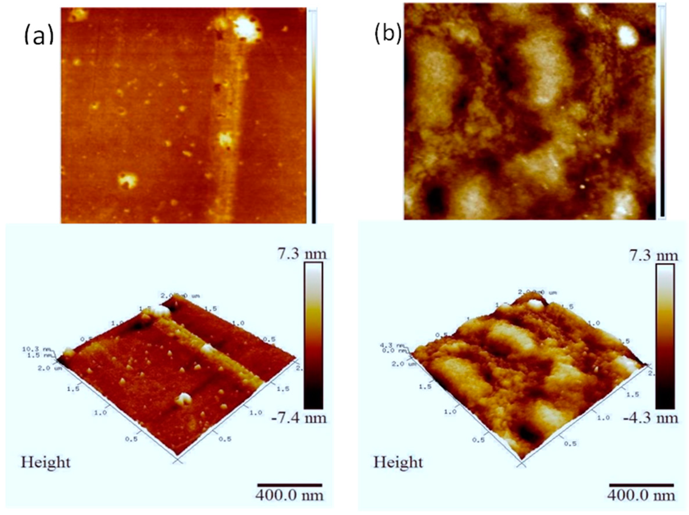
3.2. AFM Samples’ Surface Morphology

Figure 5 presents the difference in morphology relating to base sol-gel and FAS sol-gel films. In general, the AFM imaging demonstrates the uniformity of both coatings. Nevertheless, introducing the fluorinated precursor FAS has resulted in a distinct alteration in the morphology of the modified coating. This modification has caused a transition from the previously observed smooth surface in the base sol-gel to a surface with a rough texture characterized by spherical humps, as seen in the FAS-modified sol-gel [13]. These modifications may contribute to the enhanced hydrophobicity of the coating. Base and FAS sol-gel coatings differed in their Rz values, with the former measuring 4.8 nm and the latter 10.4 nm.

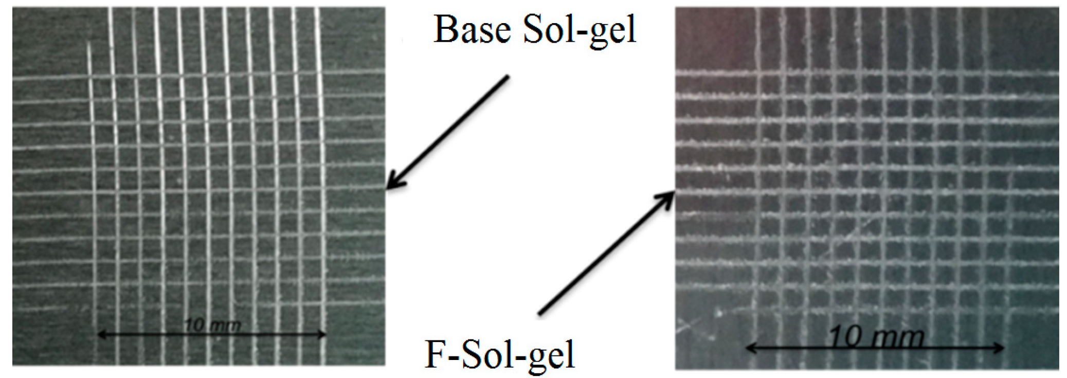
3.3. Cross-Cutting/Hatching Test

This experiment utilizes a technique that involves assessing the coating detachment of the coated sample. This can be achieved by applying angled cuts in a lattice pattern with a marking sharp tool, then using strong adhesion tape on those marks in the coating, followed by manual tape insertion out from the sol-gel film until it thoroughly penetrates the surface of the substrate. This test was conducted and assessed in accordance with the code of practice ASTM D3359 for classifying the outcomes of measuring the degree of coating detachment from the coated specimen [14,15].
Figure 6 shows the cross-hatching tests which were conducted on both coated samples, and the obtained results of this test are shown in Table 1.

3.4. Hardness Measurements

Hardness refers to a material’s capacity to withstand plastic deformation, which is quantified by the measurement of indenter penetration. Determining hardness entails quantifying the indenters’ depth and area produced by a specified geometric configuration subjected to a prescribed force and duration. Two distinct categories of hardness measurements are differentiated depending on the magnitude of the test force. The first category is the macrohardness, which involves the application of more than 1 kg of force load (9.807 N and above).
The second category is called microhardness, where the applied stress ranges between 1 to 1000 gf (9.807 × 10⁻³ to 9.807 N). Moreover, various standardized tests exist, including the Vickers and Knoop scales, and the Brinell and Rockwell methods.
This study used a Vickers indenter and applied force between a 10 to 50 gf load. The indenter under consideration has a geometric configuration characterized by a square base and an angle of penetration of 136 degrees between opposing sides (Figure 7).
The Vickers hardness values were determined by using the area of the indentation, as per Equation (2):
H V = 2 F s i n ( 136 2 ) d 2 H V = 1.854 2 F d 2 approximately
where:
F is the force.
d 2 is d1 * d2.
Both sol-gel coating systems had their microhardness tested. To test these samples, we began by utilizing a Vickers indenter between 10 and 50 gf load. For comparison, the bare AA 2024-T3 sample was tested.
The microhardness measurements of the bare and coated samples are shown in Table 2. When the FAS precursor was added to the original base sol-gel formula, the value of the hardness level decreased to 62 HV and 24 HV for the base sol-gel and FAS-modified sol-gel coating, respectively. This could make the plastic deformation of the new FAS-modified sol-gel film retain more plasticity, enabling it to absorb mechanical stress lead and reduce cracking.

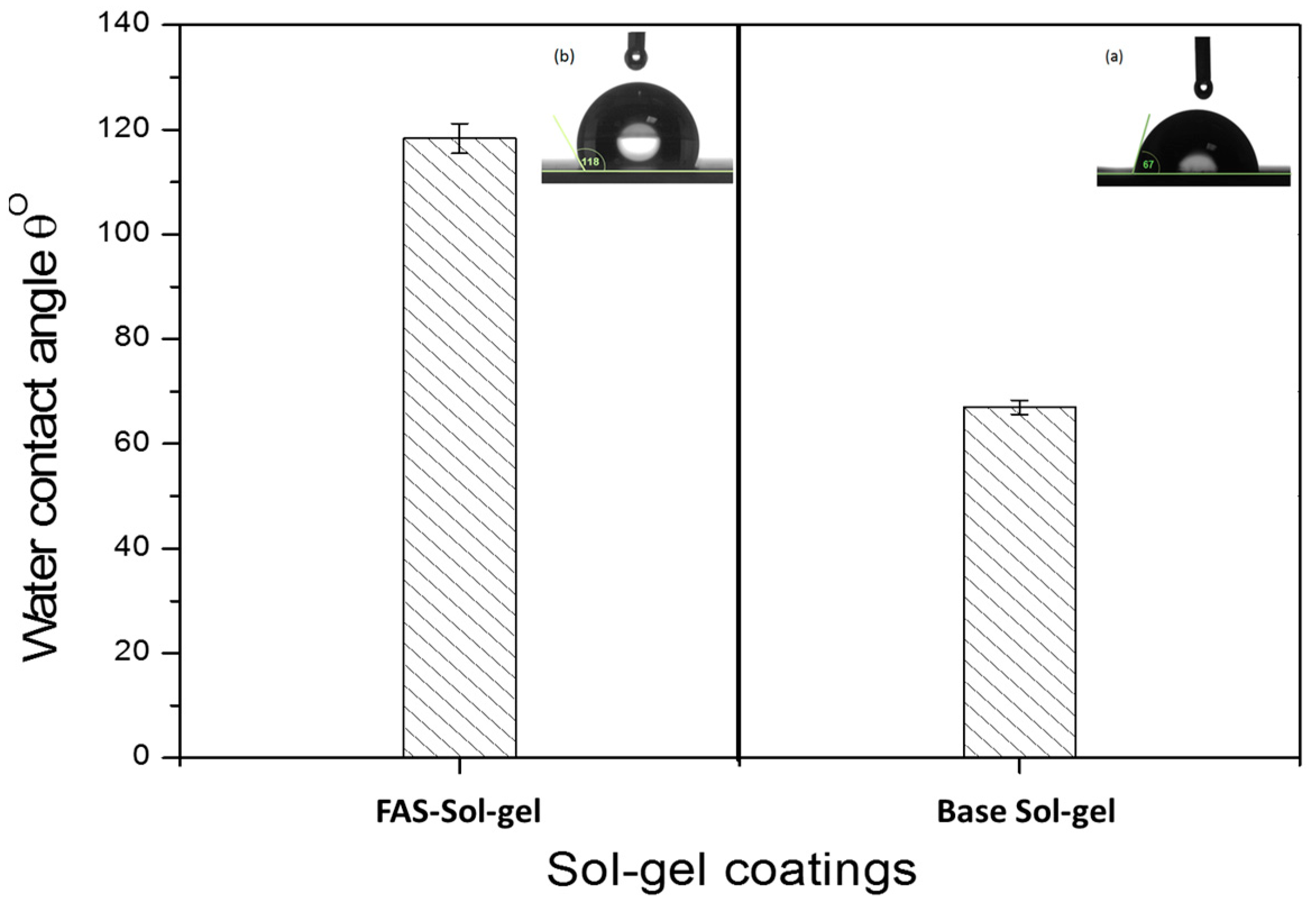
3.5. Coatings’ Water Contact Angle (WCA)

A standard bar chart illustrates the mean values of WCA droplets for both coating methods. Figure 8a displays the water contact angle measurements for the original SBX-80 coating, yielding a 67 ± 2° value. Conversely, Figure 8b illustrates the values for the FAS-modified sol-gel coating, which exhibits a significant increase to 118 ± 2°. The FAS-modified sol-gel exhibits a larger water contact angle, indicating a reduced wettability encounter with the base coatings. This phenomenon may attributed to the enhance hydrophobicity of the new FAS-modified sol-gel coating [5].

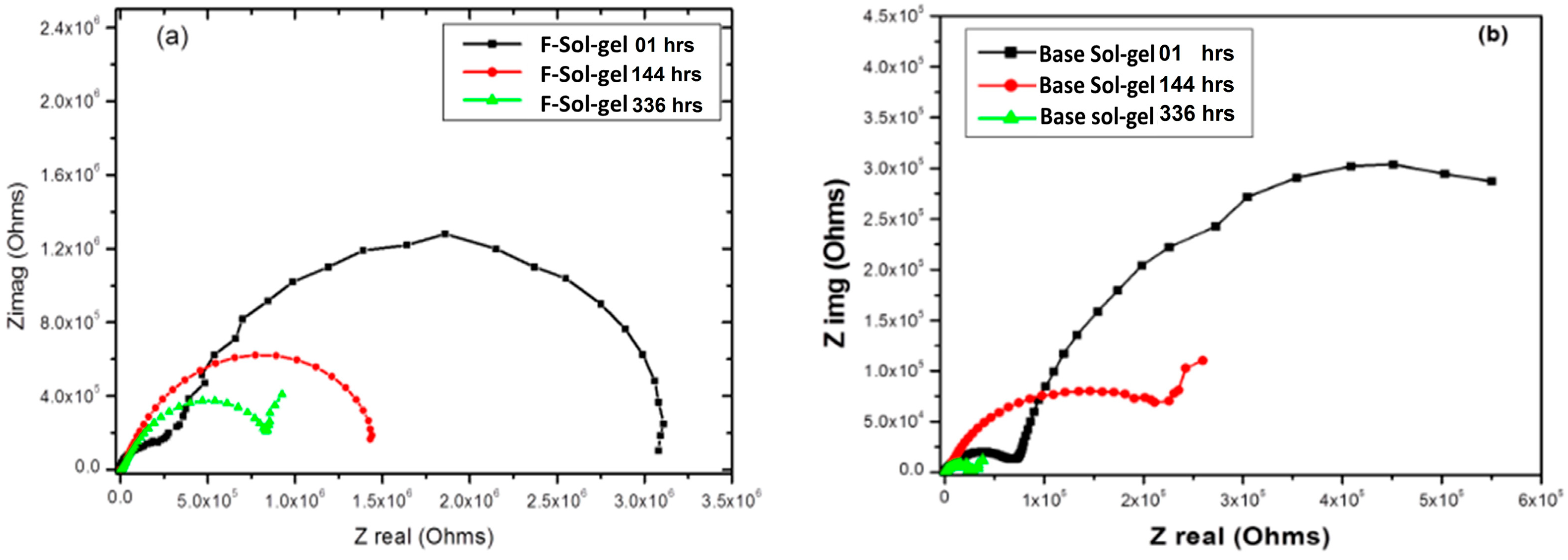
3.6. Electrochemical Corrosion Testing

When it comes to quickly assessing a coating’s ability to prevent corrosion, few techniques are as reliable as Electrochemical Impedance Spectroscopy (EIS). The long-term performance of the coatings may be predicted using data obtained from EIS measurements, which can be obtained in a concise amount of time. Nyquist plots of EIS spectra obtained from different immersion periods in NaCl solution for base Sol-gel and FAS-modified sol-gel coatings are shown in Figure 9a,b. The corrosion mechanism of the coated sample was simulated by using equivalent circuits for the first hour, after 48 h, and finally after 144 h of immersion. The fitted data show that the Rct of the FAS-modified sol-gel was more significant than the base sol-gel coating by one order of magnitude, 3.319 × 10⁶ and 7.8 × 10⁵ Ohms·cm2. Then, after 144 h of immersion, there was a dramatic drop in the Rct for both coatings by two orders of magnitude. However, the FAS-modified sol-gel Rct remained at 8.42 × 10⁵ Ohms·cm2, while the base sol-gel coating fell to 2.52 × 10⁴ Ohme.cm2, revealing that the base coating resistance deteriorated when it compared to the new FAS-modified coating.

4. Conclusions

This research reveals the impact of adding fluoroalkylsilane (FAS) to silica-based sol-gel in small ratios on its mechanical properties using atomic force microscopy (AFM) nanoindentation, cross-cut adhesion, microhardness, and water contact angle. The results show that the new modified coating with FAS had greater plasticity and could produce mechanical and corrosion protection stability, enhancing the hydrophobicity of the new surface. The coating’s optical transparency, mechanical strength, and corrosion resistance may be affected by the distribution and concentration of FASs in the sol-gel network. This study shows the synthesis circumstances and parameters of FAS-modified sol-gel coatings, which have the potential to be used in aerospace and maritime settings to protect light metals against corrosion while exhibiting outstanding chemical stability. This study found that adding fluorinated functional groups (FAS) to the base formula caused a decrease in Young’s modulus values in the time drops in hardness of the coated film, allowing the modified sol-gel to survive under lengthwise compression or tension. In addition, the surface morphology of the samples was also examined, showing homogeneity for both coatings’ systems. The FAS precursor fluorinated functional group changed the modified sol-gel’s surface morphology, potentially improving the hydrophobicity of the modified sol-gel coating system.

Author Contributions

Methodology, M.M.; validation and testing M.M.; data analysis, M.M., S.T. and A.S.; investigation, M.M.; resources, M.M.; writing—original draft preparation, M.M.; writing—review and editing, M.M., S.T. and A.S. All authors have read and agreed to the published version of the manuscript.

Funding

This research received no external funding.

Institutional Review Board Statement

Not applicable.

Informed Consent Statement

Not applicable.

Data Availability Statement

Data are contained within the article.

Acknowledgments

The authors would like to recognize the assistance provided by the Libyan Scholarship Program and the Material and Engineering Research Centre (MERI) at Sheffield Hallam University during this research programme.

Conflicts of Interest

The authors declare no conflict of interest.

References

  1. Mussa, M.H.; Dukali, M.; Rahaq, Y. A Case Study for Implementing a Plant Corrosion Inspection and Maintenance Anomaly and Integrity Management System on the Sabratha Gas Production Offshore Platform in the Mediterranean Sea. Eng. Proc. 2021, 11, 9. [Google Scholar] [CrossRef]
  2. Brinker, C.J.; Scherer, G.W. Sol-Gel Science: The Physics and Chemistry of Sol-Gel Processing, 1st ed.; George W. Scherer, C.J.B., Ed.; Academic Press: New York, NU, USA, 1990; Volume 3. [Google Scholar]
  3. Livage, J.; Sanchez, C. Sol-Gel Chemistry. J. Non-Cryst. Solids 1992, 145, 11–19. [Google Scholar] [CrossRef]
  4. Suleiman, R.; Khaled, M.; Wang, H.; Smith, T.J.T.; Gittens, J.; Akid, R.; El Ali, B.M.; Khalil, A.; Mohamad El Ali, B.; Khalil, A. Comparison of selected inhibitor doped sol-gel coating systems for protection of mild steel. Corros. Eng. Sci. Technol. 2014, 49, 189–196. [Google Scholar] [CrossRef]
  5. Kumar, D.; Wu, X.; Fu, Q.; Ho, J.W.C.; Kanhere, P.D.; Li, L.; Chen, Z. Development of durable self-cleaning coatings using organic-inorganic hybrid sol-gel method. Appl. Surf. Sci. 2015, 344, 205–212. [Google Scholar] [CrossRef]
  6. Mussa, M.H.; Rahaq, Y.; Takita, S.; Zahoor, F.D.; Farmilo, N.; Lewis, O. The Influence of Adding a Functionalized Fluoroalkyl Silanes (PFDTES) into a Novel Silica-Based Hybrid Coating on Corrosion Protection Performance on an Aluminium 2024-t3 Alloy. Mater. Proc. 2021, 7, 6. [Google Scholar] [CrossRef]
  7. Mussa, M. Development of Hybrid Sol-Gel Coatings on AA2024-T3 with Environmentally Benign Corrosion Inhibitors. Ph.D. Thesis, Sheffield Hallam University, Sheffield, UK, 2020. [Google Scholar]
  8. ASTM B209-14; Standard Specification for Aluminum and Aluminum-Alloy Sheet and Plate. ASTM International: West Conshohocken, PA, USA, 2016; p. 25.
  9. Mussa, M.H.; Farmilo, N.; Lewis, O. The Influence of Sample Preparation Techniques on Aluminium Alloy AA2024-T3 Substrates for Sol-Gel Coating. Eng. Proc. 2021, 11, 5. [Google Scholar] [CrossRef]
  10. Hiesgen, R.; Helmly, S.; Galm, I.; Morawietz, T.; Handl, M.; Friedrich, K. Microscopic Analysis of Current and Mechanical Properties of Nafion® Studied by Atomic Force Microscopy. Membranes 2012, 2, 783–803. [Google Scholar] [CrossRef] [PubMed]
  11. Hiesgen, R.; Sörgel, S.; Costa, R.; Carlé, L.; Galm, I.; Cañas, N.; Pascucci, B.; Friedrich, K.A. AFM as an analysis tool for high-capacity sulfur cathodes for Li–S batteries. Beilstein J. Nanotechnol. 2013, 4, 611–624. [Google Scholar] [CrossRef] [PubMed]
  12. Ferencz, R.; Sanchez, J.; Blümich, B.; Herrmann, W. AFM nanoindentation to determine Young’s modulus for different EPDM elastomers. Polym. Test. 2012, 31, 425–432. [Google Scholar] [CrossRef]
  13. Rahaq, Y.; Mussa, M.; Mohammad, A.; Wang, H.; Hassan, A. Highly reproducible perovskite solar cells via controlling the morphologies of the perovskite thin films by the solution-processed two-step method. J. Mater. Sci. Mater. Electron. 2018, 29, 16426–16436. [Google Scholar] [CrossRef]
  14. Tracton, A.A. Coatings Technology Handbook, 3rd ed.; Tracton, A., Ed.; Taylor & Francis Group: Boca Raton, FL, USA, 2006; ISBN 9781574446494. [Google Scholar]
  15. ASTM D3359-17; Standard Test Methods for Rating Adhesion by Tape Test. ASTM International: West Conshohocken, PA, USA, 2017.
  16. Struers Energy Certainty Duramin-40 Hardness Tester Struers. Available online: https://www.struers.com/en-GB/Products/Hardness-testing/Hardness-testing-equipment/Duramin-40#references (accessed on 20 March 2023).
Figure 1. Schematic image of EIS testing cell.
Engproc 56 00098 g001
Figure 2. Schematic drawings of evaluation of mechanical properties with force–separation curve on (right) and scheme of current measurement with conductive contact during scanning (left) [11,12].
Engproc 56 00098 g002
Figure 3. Schematic drawing of conical applied Sneddon model.
Engproc 56 00098 g003
Figure 4. Data obtained from AFM mechanical mode show the change in Young’s Modulus for both coatings.
Engproc 56 00098 g004
Figure 5. AFM images of (a) base sol-gel and (b) FAS Sol-gel.
Engproc 56 00098 g005
Figure 6. Image of the cross-cutting test for both coatings’ systems.
Engproc 56 00098 g006
Figure 7. Indenter profile and appearance of the indent on the coating surface [16].
Engproc 56 00098 g007
Figure 8. Mean bar chart of the WCA for both systems.
Engproc 56 00098 g008
Figure 9. EIS Nyquist plots of (a) the FAS-modified sol-gel coating and (b) the base sol-gel coating immersed from 1 to 336 h in NaCl solution.
Engproc 56 00098 g009
Table 1. The results of the cross-cutting test on both coatings’ systems.
OrderSample IdentifierClassificationRemoved Area Percentage
1Base Sol-gel5B0%
2FAS-Sol-gel4B–5B<5%
Table 2. Results of microhardness.
OrderSample IdentifierMeasurements Value
1AA2024-T3146 HV-0.05
2Base sol-gel62 HV-0.01
3FAS sol-gel24 HV-0.01
Disclaimer/Publisher’s Note: The statements, opinions and data contained in all publications are solely those of the individual author(s) and contributor(s) and not of MDPI and/or the editor(s). MDPI and/or the editor(s) disclaim responsibility for any injury to people or property resulting from any ideas, methods, instructions or products referred to in the content.

