Abstract
To enhance the robustness of the Global Navigation Satellite System (GNSS) against malicious attacks (e.g., spoofing), the European Galileo is working on new services, like Open Service Navigation Message Authentication (OSNMA), which provides authentication on the navigation bits, or Commercial Authentication Service (CAS), which aims to encrypt the spreading code chips. An assisted mode of the latter, named Assisted Commercial Authentication Service (ACAS), is currently under definition by the Galileo program. It uses the Timed Efficient Stream Loss-tolerant Authentication (TESLA) keys provided by OSNMA on the E1-B signal to re-encrypt some fragments of the encrypted E6-C signal, known as Re-Encrypted Code Sequences (RECSs), that are made available in the GNSS Service Centre (GSC). Once downloaded by a compatible receiver, they can be decrypted using the corresponding key and used to perform the correlation with the broadcasted E6-C signal. If that results in a correlation peak, the signal can be authenticated under certain circumstances. However, the probability of detecting this peak depends on the length of these fragments and their periodicity, since they are only provided for certain predefined instants. Indeed, if the receiver relies solely on E6-C signal and has no accurate time reference, this probability is severely degraded. This is why the nominal operating mode proposed for ACAS is to use the estimates provided by E1-B to reduce the uncertainty on the E6-C signal, so that the receiver can know precisely where these fragments are located. In the context of the PAULA project, we have developed a low-cost hardware platform based on bladeRF that allows acquiring both E1-B and E6-C samples synchronously. In this paper, we describe how to set up this platform and we characterise the alignment between the E1-B and E6-C estimates (code phase and Doppler frequency) using the real datasets obtained with such a platform, which is of key importance for the ACAS nominal mode. The results confirm the convenience of using the estimates from the E1-B signal for ACAS.
1. Introduction
In recent years, GNSS have become critical infrastructures for a wide range of applications, including transportation, agriculture, and telecommunications. However, these systems are vulnerable to malicious attacks like spoofing, which involve transmitting fake signals to deceive the receiver into computing incorrect positioning or timing information. To prevent these attacks, many techniques are being developed and implemented in GNSS receivers to verify the authenticity of the signals [1].
On the other hand, many proposals have emerged to integrate cryptographic protection into the signals themselves [2], allowing for an increase in the reliability and safety of GNSS-based applications. Galileo, the European GNSS, has been one of the most engaged entities in this area [3]. It was the first to develop a service to ensure the authenticity of the navigation message data, known as OSNMA [4]. Recently, this service has been made freely available to all users in the E1-B signal (operational capability).
Furthermore, Galileo is currently developing a new service named CAS [5], which is based on the encryption of the E6-C component at signal level to provide Spreading Code Authentication (SCA). This offers an enhanced level of security to the system, and when used together with OSNMA, is intended to provide a fully secure solution for GNSS users. These techniques are also being analysed in the forthcoming Global Positioning System (GPS) Chips-Message Robust Authentication (CHIMERA) [6].
To provide this type of authentication without modifying Galileo’s current signal plan, and without the need to store any secret keys on the receiver, an assisted mode of CAS, known as ACAS, is being defined. This is expected to be available by 2024, and involves selecting specific fragments of the E6-C signal (which is intended to be encrypted in the future) prior to its transmission. These fragments, known as Encrypted Code Sequences (ECSs), are then re-encrypted using the TESLA keys already provided by OSNMA on the E1-B signal, yet to be disclosed. The resulting RECSs are made publicly accessible through the GSC. Compatible receivers can download the necessary RECSs for their desired duration (e.g., several days or weeks) to operate autonomously.
Once the E6-C signal is broadcast, the receiver records a snapshot at the time where the ECS are expected. Later, when the corresponding key is disclosed in the E1-B signal, the receiver can decrypt the stored RECS and correlate it with the pre-recorded snapshot. A correlation peak indicates that the fragment is located where expected and, hence, the signal can be authenticated, provided that some conditions are met. For a more comprehensive explanation, interested readers can refer to [7], which also provides a description of the cryptographic operations involved in ACAS that fall outside the scope of this paper.
One critical factor influencing the performance of ACAS at the signal level is the length of the snapshot used for correlation with the decrypted RECS (i.e., the local replica). As discussed in [8], due to the nature of ACAS, relying solely on the E6-C signal can result in a significant degradation of the correlation peak detection probability, depending on the receiver’s clock calibration. To mitigate this, the envisioned nominal operating mode for ACAS is to obtain the time reference from the E1-B signal and utilise it to reduce uncertainty in the E6-C signal, as elaborated in [9].
The proof-of-concept for this mode has been examined in [7]. To further validate the assumptions made in this proof-of-concept using real measurements, we have designed and implemented an evaluation platform using bladeRF Software Defined Radio (SDR) boards. This platform enables us to capture E1-B and E6-C samples synchronously. This allows the characterisation of the alignment between the E1-B and E6-C estimates, particularly concerning the code phase and Doppler frequency, which is crucial for the nominal operation of ACAS. The results obtained show that with just a few E6-C samples, the correlation can be successfully achieved. This confirms the feasibility of implementing ACAS authentication with minimal resources on a typical user receiver.
2. SDR Evaluation Platform Based on BladeRF
This section describes the evaluation platform and provides instructions on how to configure it to enable the synchronous acquisition of E1 and E6 samples.
2.1. Hardware Description
To shorten the development time and reduce costs, we implemented our evaluation platform using Commercial Off-The-Self (COTS) SDR devices available on the market. As both the E1-B and E6-C signals need to be processed in ACAS, we first review the main characteristics of these signals, which are detailed in [10] and summarised in Table 1.

Table 1.
Signal characteristics.
In light of the range of existing technical solutions, we first determine a list of minimum requirements to narrow the search among the available SDR boards on the market:
- Frequency range including the L-band (1 to 2 GHz).
- Minimum sampling rate of 60 MSps (to provide enough accuracy for the envisaged tests).
- Minimum Analog to Digital Conversion (ADC) resolution of 8 bits (to provide enough dynamic ranges for the envisaged tests).
- Low-cost board (less than $500 per board).
- External clock reference input.
After a preliminary selection, which involved non-technical factors such as purchasing convenience, the solution retained for our platform was the bladeRF 2.0 micro board from Nuand, which is focussed on developing cost-effective SDR platforms. Its main specifications are summarised in Table 2, along with the other candidates analysed (LimeSDR [11] and Analog Devices [12]) that met all the requirements listed above. A comprehensive evaluation [13] of the available SDR boards can be found in [14], within the SDR Makerspace project [15]. For an up-to-date reference on GNSS SDR, including different receiver architectures and front ends, see [16,17]. Also, for comparison purposes, [18] presents a signal authentication device based on snapshot processing for ACAS.
Table 2.
Candidate SDR boards specifications.
Going into further detail, the bladeRF 2.0 micro boards (Figure 1) are 2 × 2 Multiple-Input Multiple-Output (MIMO) SDR boards that offer a frequency range of 47 MHz to 6 GHz and a maximum sampling rate of 61.44 MHz using a resolution of 12 bits per sample. The core of the board is the latest generation Cyclone V Field Programmable Gate Array (FPGA) from Intel (formerly Altera). The FPGA size, measured in Logic Elements (LEs), depends on the bladeRF board model considered. The models used for our platform are the ×A4, with 49 K LEs, an the ×A5, 72 K LEs. The complete list of specifications can be found in [20].
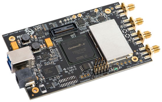
Figure 1.
bladeRF SDR board.
All the boards include an on-board PLL which allows for controlling its VCTCXO to a 10 MHz reference signal, but they can also use an external reference clock source through a dedicated surface-mounted U.FL connector. The board can be powered solely from a USB bus (USB 3.0 type), but an external power source can be supplied to ensure maximal linear performance of bias-tee peripherals if needed.
2.2. Platform Architecture
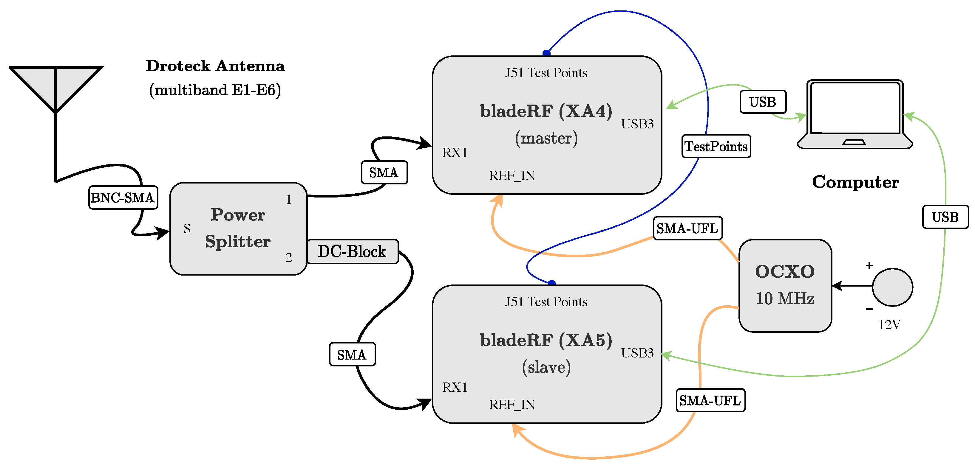
Even though the bladeRF micro 2.0 boards include 2 × 2 MIMO capabilities and therefore include two transmitters and two receiver modules, with both sharing the same oscillator. This prevents the use of the same board to acquire samples of both E1 and E6 bands simultaneously, as the former is located in the upper L-band and the latter in the lower L-band. Therefore, two boards need to record the E1 and E6 samples synchronously.
The two boards are connected to a (non-powered) Drotek multi-band antenna using a power splitter. One of the boards powers its use via its built-in bias-tee, while a DC-block is used in the other board. To prevent mismatches from using different clock sources, the boards are connected to a common external reference, specifically a Citrine Oven-Controlled Crystal Oscillator (OCXO) from Wenzel [21].
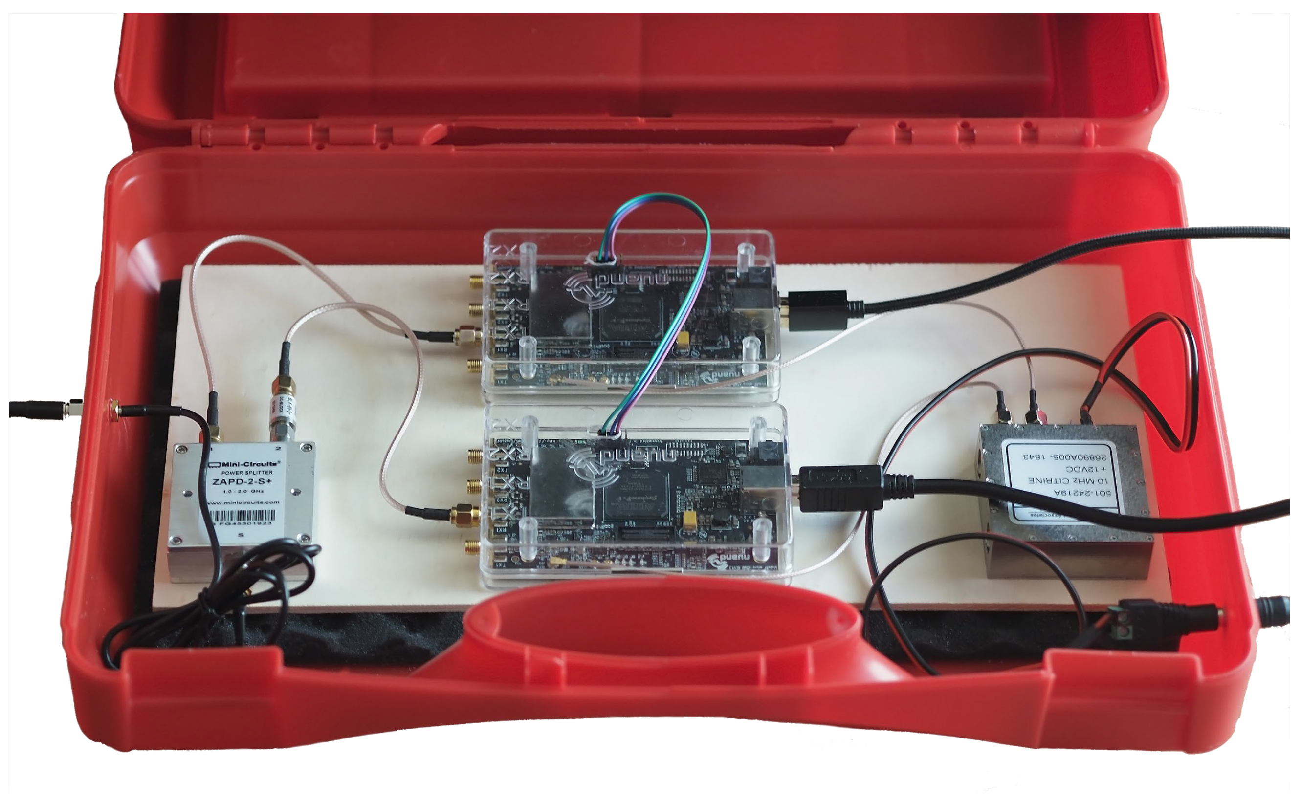
Finally, the J51 test points of each board are connected together with a jumper wire to allow the communication between boards, which permits performing the synchronisation tasks. A block diagram of the platform is shown in Figure 2, and a prototype of it is shown in Figure 3.
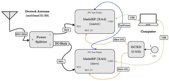
Figure 2.
Block diagram of the SDR evaluation platform.
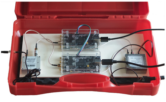
Figure 3.
Prototype of the SDR evaluation platform.
2.3. Platform Configuration
The bladeRF boards of the platform were configured using the native libbladeRF library from Nuand, although higher-level tools like the open-source SoapySDR API [22], which includes a library for interfacing with other SDR devices, can also be used. Nuand provides a basic installation guide [23] for the libbladeRF library, which can be installed on various computer platforms. On the macOS platform chosen by the authors, the MacPorts utility [24] was used. Both Intel- and ARM-based platforms have been successfully tested.
The bladeRF library allows two modes of operation: interactive and non-interactive. The latter allows for batch-processing the configuration commands from the Command Line Interface (CLI), but the authors have found some inconsistencies during the operation with the current version, where some parameters keep getting misconfigured. Therefore, the more reliable interactive mode has been used, which is activated using the command `bladeRF-cli –interactive` from the host computer terminal.
The first step is to individually configure the boards. In our case, the xA5-model board, labeled as master, is assigned to acquire the E6-C samples, while the xA4-model board, labeled as slave, acquires the E1-B ones. After successfully connecting the boards to the host, which can be verified using the `probe` command, we can check the status of the FPGA. This is done using the `version` command, which shows the size of the FPGA and whether it is loaded. If not loaded, we can download the corresponding image from [25].
The results presented in this paper were obtained using version v0.14.0 of the software, which was released on 4 April 2021. At the time of writing, the latest version available is v0.15.0 (released on 13 February 2023), which mainly adds support for oversampling and, therefore, is not expected to affect the results presented here. To load the FPGA, the command `load-fpga [filename.rbf]` is used.
To avoid the need for manually loading the FPGA every time the system is powered on, Nuand provides an autoloading mechanism [26]. This mechanism can be host-software-based or firmware-based. In the former, the libbladerf library checks if the FPGA image file is available in a list of predefined folders in the host, and loads it if found. In the latter, which is host-independent but slightly slower, the FPGA bitstream needs to be written into the device’s SPI flash. This is accomplished with the command `flash-firmware [filename.img]`. The latest FX3 firmware can also be downloaded from [27].
We can now configure the receiver parameters in the boards, either inputting the commands individually, or saving them in a script and running it with the command `run [filename.script]`. The contents of the scripts for both the master and slave boards are provided in Listing 1 and Listing 2, respectively.
| Listing 1. blade-rf-conf-master.script. |
| set frequency rx 1278.75 M set bandwidth rx 10 M set samplerate rx 20 M set agc rx off set gain rx 45 set biastee on set clock_ref enable |
| Listing 2. blade-rf-conf-slave.script. |
| set frequency rx 1575.42 M set bandwidth rx 10 M set samplerate rx 20 M set agc rx off set gain rx 46 set biastee off set clock_ref enable |
We can observe that the bias-tee is activated in the master board, as it is responsible for feeding the antenna. The Automatic Gain Control (AGC) is turned off, and the receiver gain is manually adjusted to a predetermined value that maximises the board ADC’s dynamic range. Additionally, the gain is slightly increased in the slave board to compensate for the attached DC-block’s losses. It is worth noting that the bladeRF micro 2.0 board converter has a native format of signed, complex 16-bit Q11, which implies that the values are within the range of (−2048, 2048). Finally, the last command in the script allows the use of the Oven-Controlled Crystal Oscillator (OCXO) as the external clock reference.
The next step is to configure the boards so that they can acquire samples synchronously. To do so, we start defining the test points that will be used for triggering, first in the master board and then in the slave board. This is accomplished using the scripts provided in Listings 3 and 4. Finally, we need to fire the trigger back into the master board to start acquiring samples synchronously, which is done with the command `trigger j51-1 tx fire`.
| Listing 3. blade_rf_rx_sync_master.script. |
| rx config file = master_e6.bin n = 200 M trigger j51-1 tx master trigger j51-1 rx slave rx start |
| Listing 4. blade_rf_rx_sync_slave.script. |
| rx config file = slave_e1.bin n = 200 M trigger j51-1 rx slave rx start rx wait |
The `rx config` command allows for the specification of the filename where the samples will be recorded, as well as the total number of samples to be recorded. If not specified, the native binary format will be used. However, it is also possible to use the Comma-Separated Values (CSV) format using the option `format=csv` in the `rx config` command. In our case, since we have configured the boards with a sampling rate of 20 MHz, the 200 million samples (`n = 200 M`) to be acquired correspond to a 10 s snapshot. Therefore, two files (one for E6, one for E1) will be generated, each approximately 800 MB in size, taking into account that each sample (I and Q) is coded in 2 bytes.
It is important to note that the synchronisation feature used in this evaluation platform is not documented in the official Nuand documentation for the bladeRF micro 2.0 boards. However, a similar feature is available for other boards from the same manufacturer [28], which has been used to infer the existence of this feature for the board used in our platform.
3. Results with Real Datasets
In this section, we use the real datasets obtained with the evaluation platform, which can be freely accessed (see the Data Availability section at the end of the paper), to analyse the alignment of E1 and E6 estimates. To accomplish this, the recorded snapshots are divided into smaller portions and processed individually using a custom-built MATLAB simulator to obtain these estimates. Then, a statistical comparison is performed by averaging roughly 2000 of these portions. A comparison of these estimates for a given portion is shown in Figure 4, where we can see that the width of the BOC (1,1) central peak used in E1-B is slightly wider but comparable to the BPSK(5) peak used in E6-C, as expected from the Autocorrelation Function (ACF). All the datasets used in this section were recorded under clear sky conditions, with a not lower than 45 dBHz, and that no ionospheric correction was applied.
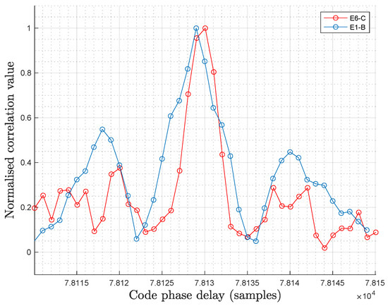
Figure 4.
E1-E6 correlation peaks comparison.
It is worth noting that, in certain instances, one of the boards of the evaluation platform misses some samples in the recording process, so that the code phase difference is affected by this amount, which should be removed in the statics computation to obtain a fair comparison of the code phase estimates.
3.1. E1-E6 Code Phase Delay Comparison
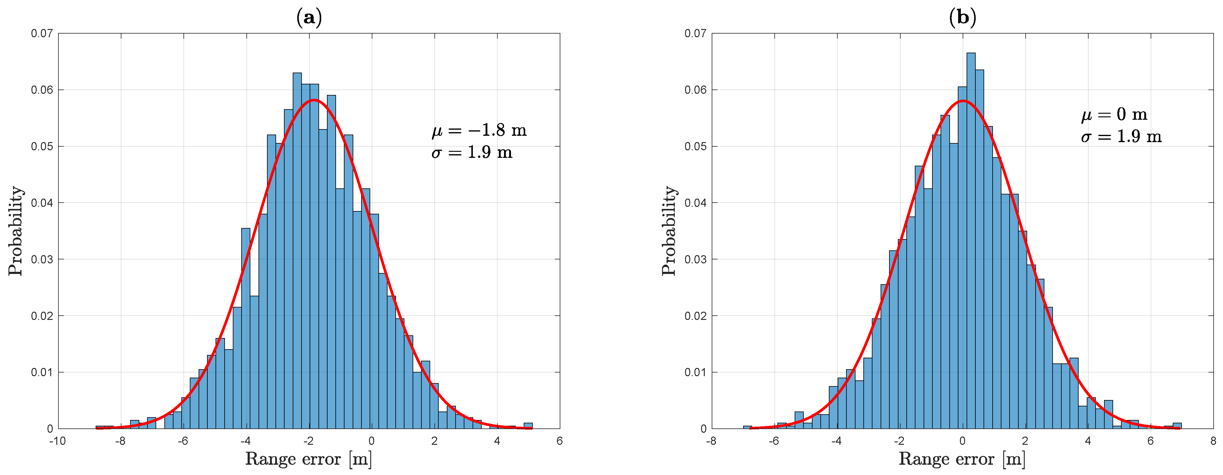
In Figure 5, we present a statistical comparison of the code phase delay difference between the E6-C and E1-B open signals. Four different real datasets are used, recorded approximately every 3 min, allowing for an analysis of the alignment with different power cycles by switching the platform on and off. Each snapshot lasts for 10 s, corresponding to 200 million samples at a sampling rate of 20 MHz. In this case, the snapshots are divided into portions of 4 ms, comprising 80,000 samples. Both the E6-C and E1-B estimates are obtained by processing a single spreading code, with durations of 1 ms and 4 ms, respectively. The obtained distribution exhibits, as expected, a non-centred Gaussian-like shape, the variance of which is related to the sample noise. A Gaussian curve (in red) is fitted to the experimental data (in blue) to interpolate the mean and variance for each snapshot.
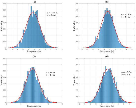
Figure 5.
E1-B vs. E6-C code phase delay comparison ( MHz, 2000 portions averaged, different power cycles). (a) Dataset A. (b) Dataset B. (c) Dataset C. (d) Dataset D.
The results demonstrate a high level of consistency with respect to the spread of the estimates, with a variance of around 2.5 m when only one E6-C spreading code is used for the acquisition. The observed bias primarily originates from the ionospheric effects and the hardware biases after power cycles resulting from the use of two distinct SDR boards in the platform.
In Figure 6a, we compare the code phase delay between E1-B and E6-C using an additional dataset. To obtain more precise estimates, we use a sampling rate of 60 MHz, which is close to the maximum frequency supported by the bladeRF boards used in the platform for the nominal 12-bit mode. In this case, we use the same coherent integration time of 4 ms for both bands. Currently, this involves performing a secondary code acquisition on E6-C to coherently combine four 1 ms codes. However, in the nominal operating mode of ACAS, the receiver is synchronised with E1-B and, therefore, should know the location of the E6-C secondary code. Nevertheless, once the E6-C signal is encrypted and real ECSs are processed, the secondary code would not play any role, as the ECS provides the encrypted sequence after multiplying the keystream with the E6-C primary and secondary codes. As a result, the variance is reduced to less than 2 m.
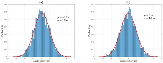
Figure 6.
Code phase delay comparison, dataset E ( MHz, 2000 portions averaged, 4 ms of coherent integration time for both bands). (a) E1-B vs. E6-C. (b) E6-B vs. E6-C.
To diminish the hardware bias produced by using two distinct boards, we also provide a comparison of the code phase delay between the E6-B and E6-C using the latest dataset, but now processing a unique snapshot from the same board. As we can observe in Figure 6b, the obtained distribution exhibits a centred Gaussian-like shape in this case.
3.2. E1-E6 Doppler Frequency Comparison
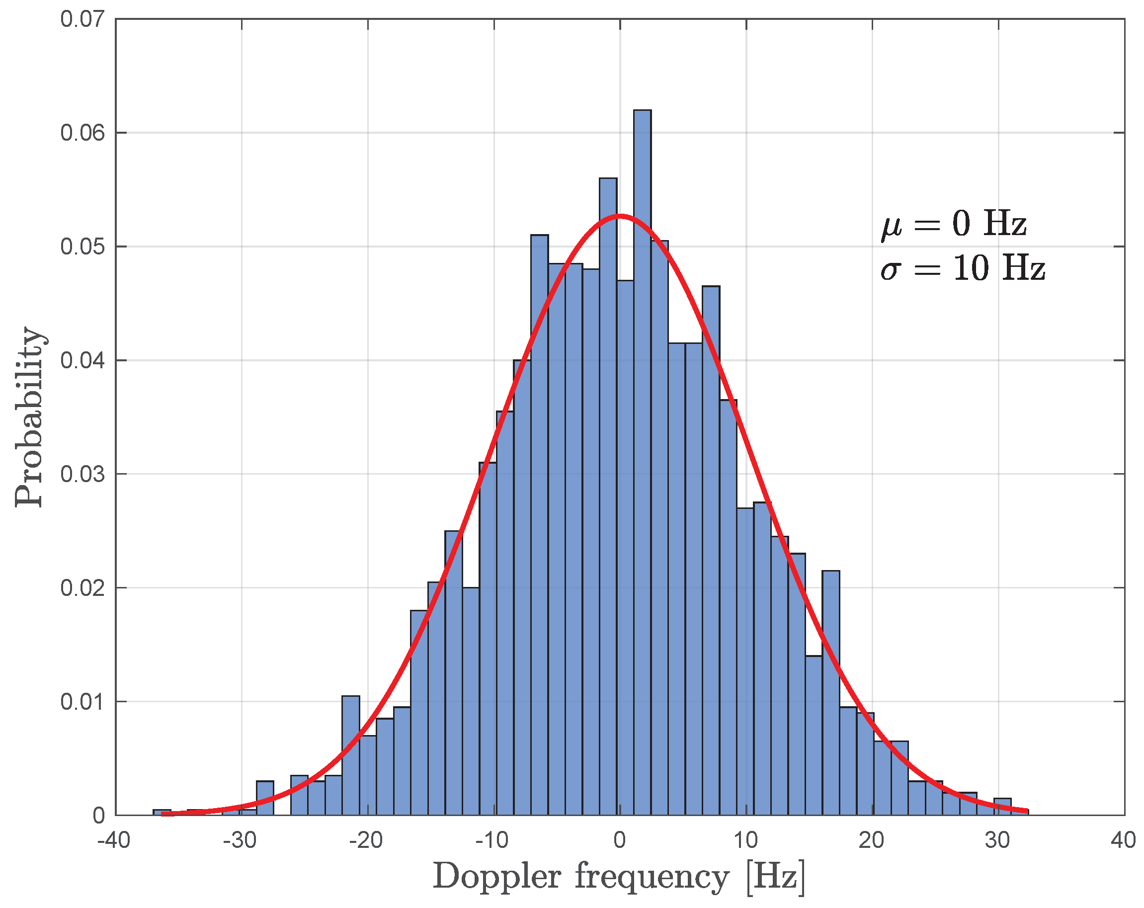
In Figure 7, we compare the Doppler frequency estimates for both E6 and E1 bands using the latest dataset. For this comparison, we consider the relationship between both carrier frequency bands; hence, the Doppler frequency used for E6 is computed from the estimate obtained in E1 multiplied by the ratio . We also use a coherent integration time of 4 ms for both bands. The obtained results indicate that the differences are sufficiently small to justify using a reduced frequency search space in E6 based on the E1 estimate.

Figure 7.
E1-B vs. E6-C Doppler frequency comparison, dataset E.
4. Conclusions and Further Work
ACAS aims to provide a mechanism to authenticate the Position, Velocity and Timing (PVT) using current Galileo signals. The OSNMA keys available in the E1-B signal are used to encrypt/decrypt some fragments of the E6-C signal, which are intended to be encrypted in the future. Unlike conventional approaches, in ACAS the receiver is required to record a snapshot at the time where these fragments are expected, as they are only broadcasted during certain instants. Therefore, the envisioned nominal operating mode is to first obtain a time reference from the open E1-B signal to reduce the uncertainty on the E6-C signal.
This is why analysing the alignment of the E1 and E6 estimates, which includes the code phase delay and Doppler frequency, is crucial for this mode. In this paper, we have developed a low-cost evaluation platform based on bladeRF SDR boards to examine this alignment using real datasets. The samples of E1 and E6 components were captured synchronously using an inferred, undocumented feature of the bladeRF boards. The results show the consistency between the E1 and E6 estimates, confirming the viability of ACAS using limited resources for typical GNSS receivers.
Further work will include the preliminary evaluation of ACAS using the existing E1-B and E6-C open signals using the evaluation platform used in this work [29].
Author Contributions
Software, validation, writing—original draft preparation, R.T.-G.; supervision, writing—review and editing, I.F.-H., J.A.L.-S. and G.S.-G. All authors have read and agreed to the published version of the manuscript.
Funding
This work was supported, in part, by the European Commission Defence Industry and Space Satellite Navigation (DEFIS) contract DEFIS/2020/OP/0002 and, in part, by the Spanish Agency of Research project PID2020-118984GB-I00 and by the Catalan ICREA Academia Programme. The views expressed herein can in no way be taken to reflect the official opinion of the European Commission.
Institutional Review Board Statement
Not applicable.
Informed Consent Statement
Not applicable.
Data Availability Statement
The datasets of real samples, recorded with the SDR evaluation platform used for this paper, can be downloaded from https://spcomnav.uab.es/resources/acas_datasets (accessed on 1 May 2023).
Acknowledgments
The authors would like to thank the PAULA project participants, J. Winkel, and C. O’Driscoll, for their discussions and contributions.
Conflicts of Interest
The authors declare no conflicts of interest.
References
- Pozzobon, O.; Canzian, L.; Danieletto, M.; Chiara, A.D. Anti-spoofing and open GNSS signal authentication with signal authentication sequences. In Proceedings of the 5th ESA Workshop on Satellite Navigation Technologies and European Workshop on GNSS Signals and Signal Processing (NAVITEC), Noordwijk, The Netherlands, 8–10 December 2010; pp. 1–6. [Google Scholar] [CrossRef]
- Scott, L. Anti-spoofing & authenticated signal architectures for civil navigation systems. In Proceedings of the 16th International Technical Meeting of the Satellite Division of The Institute of Navigation (ION GPS/GNSS), Portland, OR, USA, 9–12 September 2003; pp. 1543–1552. [Google Scholar]
- Fernandez-Hernandez, I.; Vecchione, G.; Díaz-Pulido, F. Galileo authentication: A programme and policy perspective. In Proceedings of the 69th International Astronautical Congress, Bremen, Germany, 1–5 October 2018. [Google Scholar]
- Fernandez-Hernandez, I.; Rijmen, V.; Seco-Granados, G.; Simon, J.; Rodríguez, I.; Calle, J.D. A navigation message authentication proposal for the Galileo open service. Navig. J. Inst. Navig. 2016, 63, 85–102. [Google Scholar] [CrossRef]
- European Commission. Call for Tenders (DEFIS/2020/OP/0002)—Test Platform on Galileo HAS/CAS/OSNMA—Tender Specifications. 2020. Available online: https://etendering.ted.europa.eu/cft/cft-display.html?cftId=6271 (accessed on 29 April 2023).
- Anderson, J.M.; Carroll, C.K.L.; DeVilbiss, N.P.; Gillis, J.T.; Hinks, J.C.; O’Hanlon, B.W.; Rushanan, J.J.; Scott, L.; Yazdi, R.A. Chips-Message Robust Authentication (Chimera) for GPS Civilian Signals. In Proceedings of the 30th International Technical Meeting of the Satellite Division of the Institute 2388 of Navigation (ION GNSS+ 2017), Portland, OR, USA, 25–29 September 2017; Institute of Navigation: Portland, OR, USA, 2017. [Google Scholar]
- Fernandez-Hernandez, I.; Winkel, J.; O’Driscoll, C.; Cancela, S.; Terris-Gallego, R.; Seco-Granados, G.; López-Salcedo, J.A.; Dalla Chiara, A.; Sarto, C.; Blonski, D.; et al. Semi-Assisted Signal Authentication for Galileo: Proof of Concept and Results. IEEE Trans. Aerosp. Electron. Syst. 2023, 59, 4393–4404. [Google Scholar] [CrossRef]
- Terris-Gallego, R.; Fernandez-Hernandez, I.; López-Salcedo, J.A.; Seco-Granados, G. Guidelines for Galileo Assisted Commercial Authentication Service Implementation. In Proceedings of the International Conference on Localization and GNSS (ICL GNSS), Tampere, Finland, 7–9 June 2022. [Google Scholar]
- Terris-Gallego, R.; López-Salcedo, J.A.; Seco-Granados, G.; Fernandez-Hernandez, I. Operating Modes and Performance Evaluation of Galileo Assisted Commercial Authentication Service. In Proceedings of the Institute of Navigation Conference (ION+ GNSS 2022), Denver, CO, USA, 19–23 September 2022. [Google Scholar]
- European Commission. European GNSS (Galileo) Open Service—Signal-in-Space Interface Document v2.0, European Union 2021. Available online: https://www.gsc-europa.eu/sites/default/files/sites/all/files/Galileo_OS_SIS_ICD_v2.0.pdf (accessed on 29 April 2023).
- LimeMicro Website—LimeSDR. Available online: https://limemicro.com/products/boards/limesdr/ (accessed on 29 April 2023).
- Analog Devices Website—ADRV9364-Z7020. Available online: https://www.analog.com/en/design-center/evaluation-hardware-and-software/evaluation-boards-kits/ADRV9364-Z7020.html (accessed on 29 April 2023).
- SDR Makerspace Wiki. Available online: https://gitlab.com/librespacefoundation/sdrmakerspace/sdreval/-/wikis/home (accessed on 29 April 2023).
- Csete, A.; Christiansen, S. Evaluation of SDR Boards and Toolchains—Final Report; Technical Report; European Space Agency, Libre Space Foundation, Online; 2020; Available online: https://www.klofas.com/blog/2020/satnogs-station-and-minicircuits-lna-modifications/Evaluation_of_SDR_Boards-1.0.pdf (accessed on 29 April 2023).
- SDR Makerspace Website. Available online: https://sdrmaker.space (accessed on 30 April 2023).
- Borre, K.; Fernandez-Hernandez, I.; López-Salcedo, J.A.; Zahidul, M.; Bhuiyan, H. GNSS Software Receivers; Cambridge University Press: Cambridge, UK, 2022. [Google Scholar]
- Akos, D.; Arribas, J.; Dovis, F.; Di Torino, P.; Fernandez-Hernandez, I.; Humphreys, T.; Salcedo, J.A.L.; Psiaki, M.L.; Tech, V.; Rügamer, A.; et al. GNSS Software Defined Radio: History, Current Developments, and Standardization Efforts. In Proceedings of the 35th International Technical Meeting of the Satellite Division of The Institute of Navigation (ION GNSS+), Online, 20–24 September 2021. [Google Scholar]
- O’Driscoll, C.; Caparra, G. Nautilus: An embedded navigation authentication testbed. In Proceedings of the 34th International Technical Meeting of the Satellite Division of the Institute of Navigation, ION GNSS+, Online, 20–24 September 2021; pp. 3698–3710. [Google Scholar] [CrossRef]
- Nuand Website—2023-02 Release. Available online: https://www.nuand.com/2023-02-release-122-88mhz-bandwidth (accessed on 1 May 2023).
- Nuand Website—BladeRF 2.0 Micro. Available online: https://www.nuand.com/bladerf-2-0-micro/ (accessed on 29 April 2023).
- Wenzel Citrine OCXO 501-24219. Available online: https://www.quanticwenzel.com/wp-content/parts/501-24219.pdf (accessed on 29 April 2023).
- Soapy SDR Wiki. Available online: https://github.com/pothosware/SoapySDR/wiki (accessed on 30 April 2023).
- Nuand Wiki—bladeRFInstallation. Available online: https://github.com/Nuand/bladeRF/wiki/ (accessed on 30 April 2023).
- MacPorts Installation. Available online: https://www.macports.org/install.php (accessed on 1 May 2023).
- Nuand Website—FPGA Images. Available online: https://www.nuand.com/fpga_images/ (accessed on 1 May 2023).
- Nuand Website—FPGA Autoloading. Available online: https://github.com/Nuand/bladeRF/wiki/FPGA-Autoloading (accessed on 1 May 2023).
- Nuand Website—FX3 Images. Available online: https://www.nuand.com/fx3_images/ (accessed on 1 May 2023).
- Nuand Forum—Synchronized TRX. Available online: https://github.com/Nuand/bladeRF/tree/master/host/examples/bladeRF-cli/sync_trx (accessed on 30 April 2023).
- Terris-Gallego, R.; López-Salcedo, J.A.; Seco-Granados, G.; Fernandez-Hernandez, I. Preliminary Evaluation of Galileo ACAS using Existing E1-E6 Open Signals and a Low-Cost SDR Platform. In Proceedings of the Institute of Navigation Conference (ION+ GNSS 2023), Long Beach, CA, USA, 25–27 January 2023. [Google Scholar]


Disclaimer/Publisher’s Note: The statements, opinions and data contained in all publications are solely those of the individual author(s) and contributor(s) and not of MDPI and/or the editor(s). MDPI and/or the editor(s) disclaim responsibility for any injury to people or property resulting from any ideas, methods, instructions or products referred to in the content. |
© 2023 by the authors. Licensee MDPI, Basel, Switzerland. This article is an open access article distributed under the terms and conditions of the Creative Commons Attribution (CC BY) license (https://creativecommons.org/licenses/by/4.0/).