1. Introduction
Civil aviation shows an increasing dependence on Global Navigation Satellite Systems (GNSS) for navigation, both en route as well as in critical operations such as takeoff and landing. The use of GNSS can improve the accuracy, integrity, and continuity of positioning, communication, and surveillance services. However, due to the low power of the signals, GNSS is also vulnerable to radio frequency interference (RFI). In our current society, the interference threat is of increasing relevance. In 2022, the European Union Aviation Safety Agency (EASA) issued a warning in which authorities and air operators were warned for the intensified occurrence of GNSS jamming and spoofing in proximity of the Ukraine conflict zone [
1] and the International Telecommunication Union (ITU) issued a circular letter in which the jamming and spoofing threat for receivers onboard aircraft was addressed [
2]. In March 2023, the International Federation of Air Line Pilots (IFALPA) issued a statement warning pilots in the Pacific for radio interference and GNSS jamming [
3]. Although these indications are directly related to a conflict zone, it is to be expected that occurrences of harmful GNSS interference to civil aviation will increase in the future.
To increase aviation resilience against the threat of jamming and spoofing, the European Commission funded AIRING, a study on aviation resilience to GNSS frequency jamming and cyber threats [
4]. As part of this study, multiple onboard interference detection and mitigation techniques were tested. Controlled Reception Pattern Antennas (CRPA) can actively adjust their gain pattern, thereby suppressing interferences. CRPAs were originally developed for use in the military domain, but have found their way to civil applications. They can also be used to increase GNSS interference robustness in civil aviation. In this paper, a variation of the MUltiple SIgnal Classification (MUSIC) algorithm is used to develop a virtual software-based 4-element CRPA antenna. The tests to assess the RFI detection, Angle of Arrival (AoA) estimation, and mitigation capabilities are described. The aim is to not only discuss the results obtained for this software-based CRPA configuration, but to also provide insight into the processing steps of this simulation-based test method and the possible applicability on a civil aircraft.
2. MUSIC
The antenna elements of a CRPA are connected to a central processing unit where the signals from the different antenna elements are weighted and linearly combined to form a single output signal. Effectively, the reception pattern of the combined antenna is modified by the weighing, creating flexible nulls and peaks in the reception pattern. The MUSIC algorithm is a subspace-based algorithm that can be used for direction finding of signals in a narrow frequency band [
5,
6]. For this project, a variation of the MUSIC algorithm is adapted to be the central processing unit of the CRPA under test.
MUSIC uses eigenvalue decomposition to determine the Angle of Arrival and the power of the interference signals. The CRPA additionally determines a weight vector orthogonal to the interference signals. To mitigate the interference, the obtained weight vector is multiplied with the signals received by the different antenna elements, thereby steering nulls with the appropriate depths in the combined radiation pattern in the direction of the interference.
The signal received on the different antenna elements is written to
m by the
n matrix
X, where
m is the number of antenna elements and
n is the number of complex In-phase Quadrature (IQ) samples to be processed. The sample correlation matrix
is defined as
where the
operator indicates the complex conjugate transpose of a matrix. Performing a singular value decomposition of the sample correlation matrix results in a diagonal matrix
with the eigenvalues on the diagonal, an
m by
m unitary matrix U of which the column vectors span the orthonormal basis of the signal space and the noise space, and the complex conjugate transpose
of the
m by
m unitary matrix
V.
The eigenvalues in
and its respective eigenvectors in
U are sorted based on decreasing eigenvalues. For
p interference signals, the signal space
that contains the interference signals is defined by the first
p eigenvectors and the noise space
is defined by eigenvectors
to
m. To determine whether interference is present, the eigenvalues of the signal space are compared to a detection threshold. For GNSS, the satellite signals can have any AoA above the horizon; therefore, the desired hemispherical antenna radiation pattern with upward focus is wide. To maintain an optimum gain pattern in the case of no interference, the complex gain vector
is chosen to only use the gain of a single central antenna element and therefore reduces to a unit vector with a single non-zero value (in a generalized form,
is defined as [1, 0, …, 0]
). The weight vector
is determined by projecting the complex gain vector to the noise space and scaling the projection to maintain unitary amplitude in the original direction of
.
By using this method for the weight vector determination, the gain of the central element remains constant and the complex gain of the other antenna elements is adjusted to place a null in the direction of the incoming interference signal. Apart from the wide antenna gain pattern that is maintained in this configuration, an extra advantage is that no inverse matrices are required. Instead, the noise space derived in AoA detection is directly used to update the CRPA weights.
The steering vector
for a specified Angle of Arrival can be calculated from the spatial distribution of the antenna elements. By comparison of the response of the cost function
for different steering vectors, and for determining for which steering vector the cost function has its minimum, both the azimuth and elevation of the incoming interference signal can be determined. Instead, the noise space derived in AoA detection is directly used to update the CRPA weights.
Implementation
In the MUSIC implementation developed in this project, the number of potential interference sources is fixed to one. Only one interference signal can be detected and mitigated. To improve the computational efficiency of the algorithm, the AoA estimation is split into two steps. First, a coarse estimate is obtained by comparing the steering vectors of 50 sectors. The sector that contains the interference signal is then subjected to a refinement over 10 sectors. This means that the final resolution in azimuth is 0.72° and the resolution in elevation is 0.36°. The use of a coarse step and a refinement step reduces the number of evaluation steps from 450 to 60 per AoA evaluation and therefore significantly improves the calculation time to reach the same resolution. The MUSIC algorithm is configured to use
samples for every iteration. The layout of the antenna elements is given in
Table 1.
3. Test Architecture
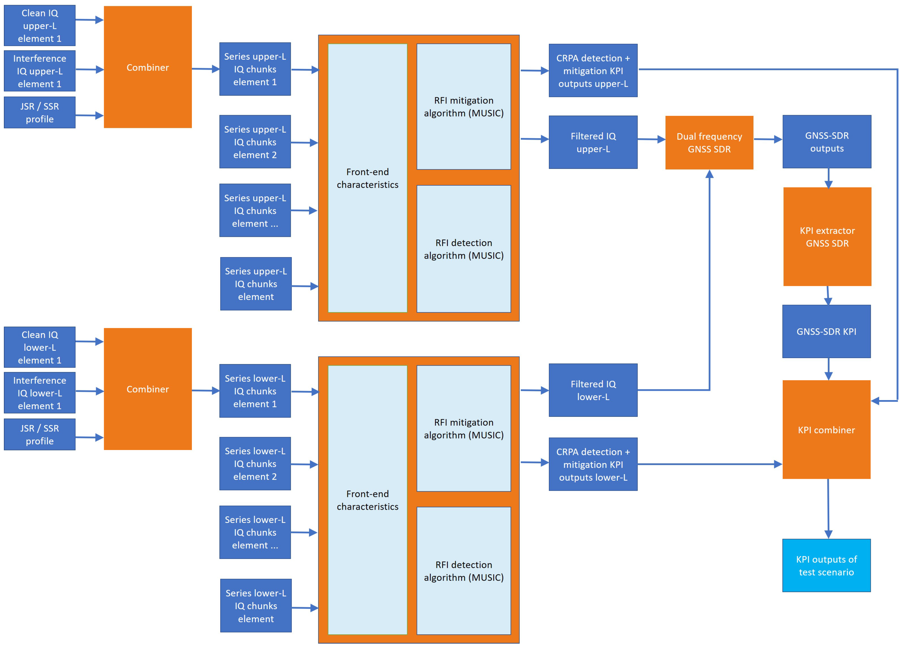
To test the software CRPA antenna for the set of scenarios, a processing pipeline is developed. The processing pipeline consists of five steps.
Since the test of this software CRPA antenna is part of a larger test campaign concerning multiple consortium partners that each test a different detection and/or mitigation technique, the simulation of the input IQ files (step 1) is centralized. The input data are generated at a baseband frequency with a sample rate of 25 Msamples/s. The IQ files consist of interleaved I shorts and Q shorts. For each frequency band (upper L-band and lower L-band), separate clean signal files and interference files are simulated and distributed to the respective consortium partners. The CRPA under test consists of four antenna elements, to account for the spatial distribution of the antenna elements, the input IQ files are simulated for each antenna element individually.
The block diagram of the processing pipeline is displayed in
Figure 1. This pipeline accounts for the processing steps after data distribution (steps 2 to 5). To run the processing pipeline, the settings for the different steps are summarized in a
.csv file. A script is written to automatically guide the files through the processing pipeline.
The clean nominal signal, the interference signal, and a predefined jamming to the signal ratio (JSR) or spoofing to the signal ratio (SSR) profile over time are combined by each individual partner to a series of smaller-sized chunks. In addition, a white Gaussian noise with a 0 dB signal-to-noise ratio (SNR) in a 4 MHz bandwidth is added to the signal.
The application of mitigation is indicated in the general configuration file used by the script defining the test scenarios. Using the input IQ chunk series of the four antenna elements as input, the CRPA implementation determines whether interference was present. When interference is detected, the AoA estimation and mitigation are performed.
As the output of the CRPA is a Radio Frequency (RF) signal, the output still needs to be processed via a GNSS receiver. In this project, we have used the GNSS-SDR software receiver. GNSS-SDR is an open-source GNSS software-defined receiver platform capable of processing multi-frequency multi-constellation input signals. GNSS-SDR is configured to operate in multi-frequency, multi-constellation mode. The configuration includes 10 channel for each of the compatible signal types: GPS L1 C/A, Galileo E1 B/C, GPS L5, and Galileo E5a. Although the goal of this test is not to design or optimize a GNSS receiver architecture, the receiver settings must be agreed on between the different AIRING partners to be able to compare the detection and mitigation techniques under test.
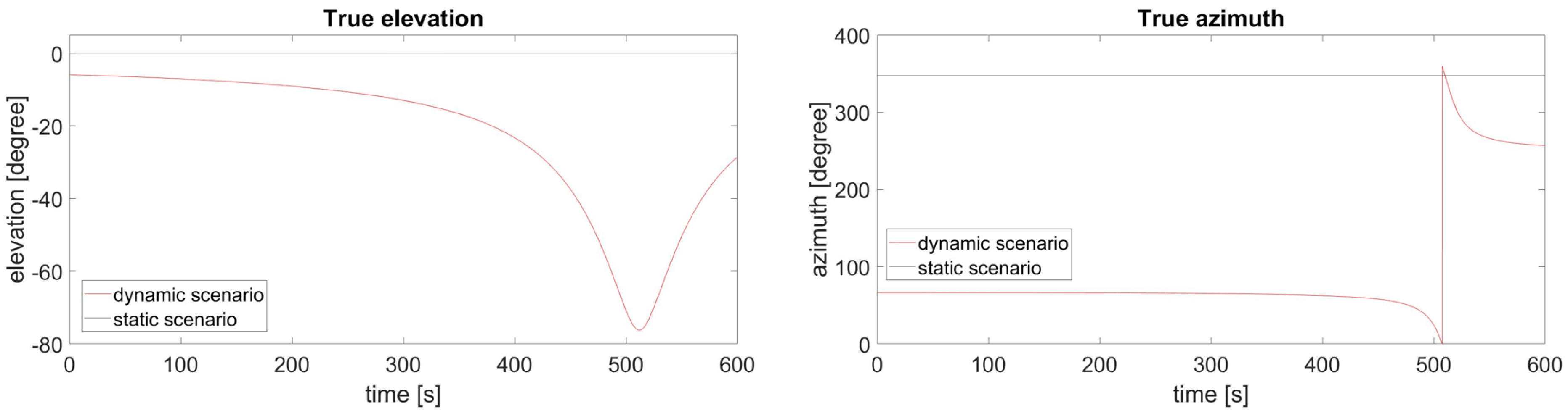
4. Test Scenarios
In the AIRING project, a number of test scenarios is defined with the aim to cover a range of different types of attacks. The CRPA implementation is tested for a subset of these test scenarios, including scenarios with different types of dynamics and different types of interferences. Each scenario runs for 10 min. In the static scenarios, the true azimuth of the interference is 348.2° and the true elevation of the interference is 0.0°. The dynamic scenarios are designed to simulate an in-flight situation where the receiver has a constant velocity of approximately 800 km/h. The true azimuth and elevation of the static interference source with respect to the dynamic receiver are plotted as a function of time in
Figure 2. To be able to determine the maximum JSR or SSR for which the detection and/or mitigation technique is effective, the respective JSR and SSR are gradually increased over time. In
Table 2, an overview of the test scenarios is given. The JSR profiles for the static and dynamic jamming scenarios are displayed in
Figure 3.
To run one scenario consisting of both upper L-band and lower L-band signals, four sets of two clean and two interference IQ files are needed, with each file respectively being 58 Gb. The processing of a single scenario on a four-core machine takes approximately 75 h. The file size and scenario duration put a considerable strain on the available memory, storage capacity, and efficiency of the processing pipeline.
5. Test Results
For the static jamming scenarios, the JSR gradually increases from 5 to 45 dB. An inspection of
Figure 3 shows that for the static scenario, saturation seems to occur at a JSR of 35.77 dB and higher. This means that after a simulation time of 390 s, the input signals start to become affected by saturation effects of the I and Q values. For the static jamming scenarios including interference (the dirty run and the mitigated run), they can become unreliable upon saturation.
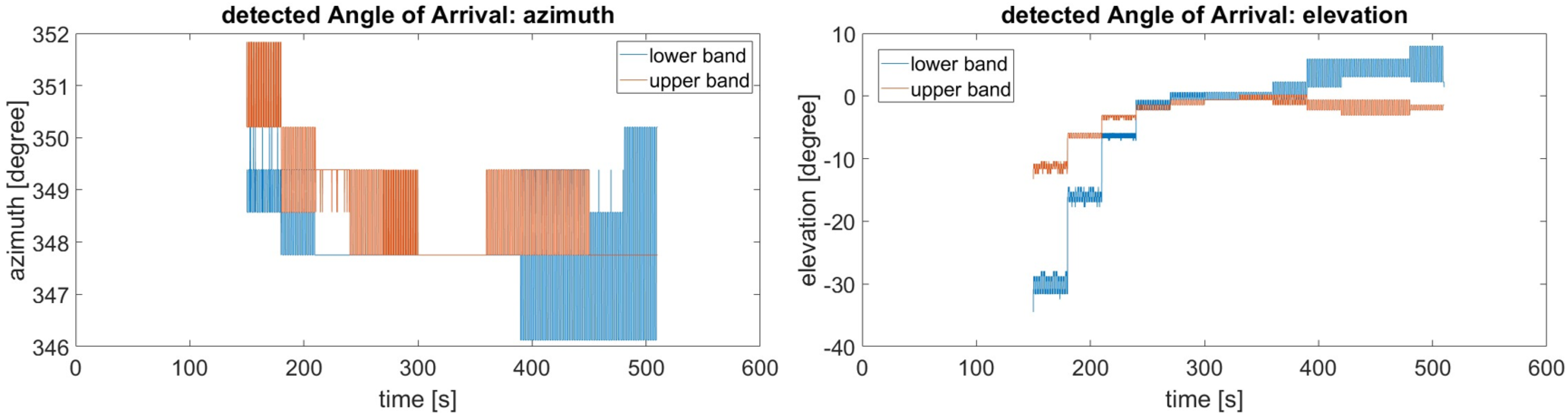
The chirped jamming signal, continuous wave jamming signal, and noise-like jamming signal were detected via the CRPA implementation. The three jamming signal types were all first detected at the moment the RFI power surpassed the detection threshold, which was at 11.15 dB JSR. The pulsed interference (12.5 μs pulse duration, 1% duty cycle) was not detected. For all static cases, the first interference detection in the lower band and the upper band occurred simultaneously and mitigation was applied directly when the detection flag was raised. To illustrate the results obtained from the performed tests, the results for the static chirp are taken as an example. The AoA estimates and power estimate for the interference signal obtained for the static chirp scenario are displayed in
Figure 4. The azimuth estimate is accurate and the estimate obtained from the lower L-band and the upper-L band are in agreement. The elevation estimate shows larger variations over time, and a larger difference between the estimate obtained from the lower L-band signals and upper L-band signals. It is expected that the difference in accuracy between the azimuth and elevation estimates can be explained using the geometry of the CRPA with respect to the test scenario.
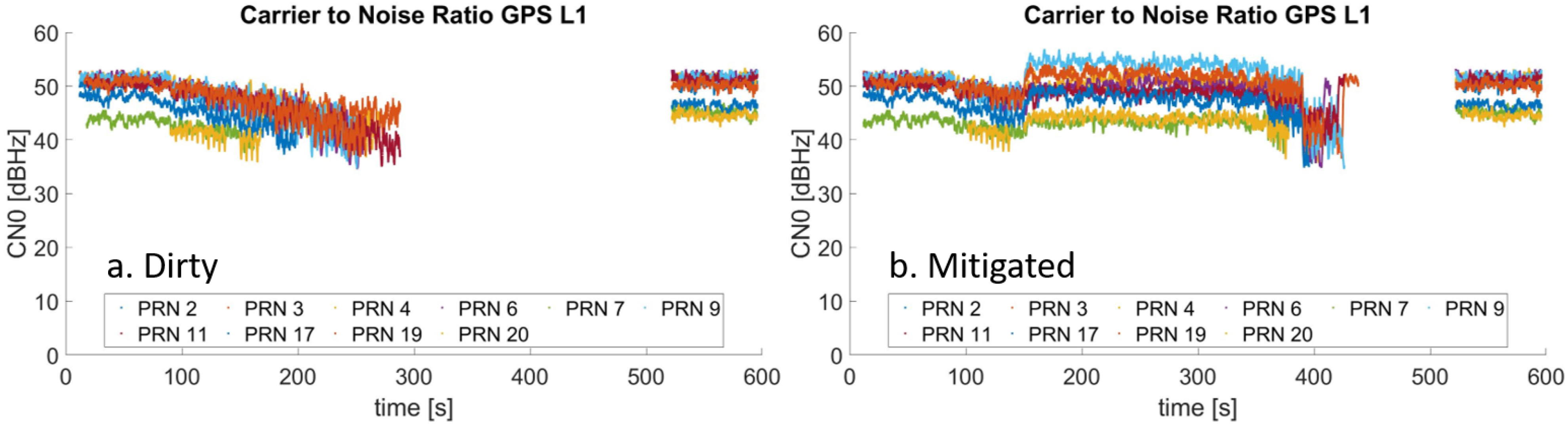
Comparison of the GNSS-SDR output of the dirty run on the interfered signal, and the mitigated run provides insight into the effectiveness of the applied mitigation. The difference in carrier to noise (CN0) between the dirty run and the mitigated run shows that in general, the mitigation helps to keep the tracks locked to a signal up to a higher jamming power. As an example, the carrier-to-noise plots of the static chirp scenario are displayed in
Figure 5. The CN0 of some of the tracked satellites in the mitigated signal shows an increase with respect to the CN0 of the tracked satellites in the clean signal. To apply mitigation, the CRPA gain pattern is adjusted. This can result in an increased gain in certain directions and can therefore increase the CN0 of satellite signals in certain directions. The effectiveness of the mitigation does depend on the type of interference. Mitigation seems to be most beneficial in the case of continuous wave jamming and chirped jamming. Pulsed jamming was not effective in disturbing the signal and was neither detected nor mitigated. Noise-like interference does not seem to be suppressed by mitigation.
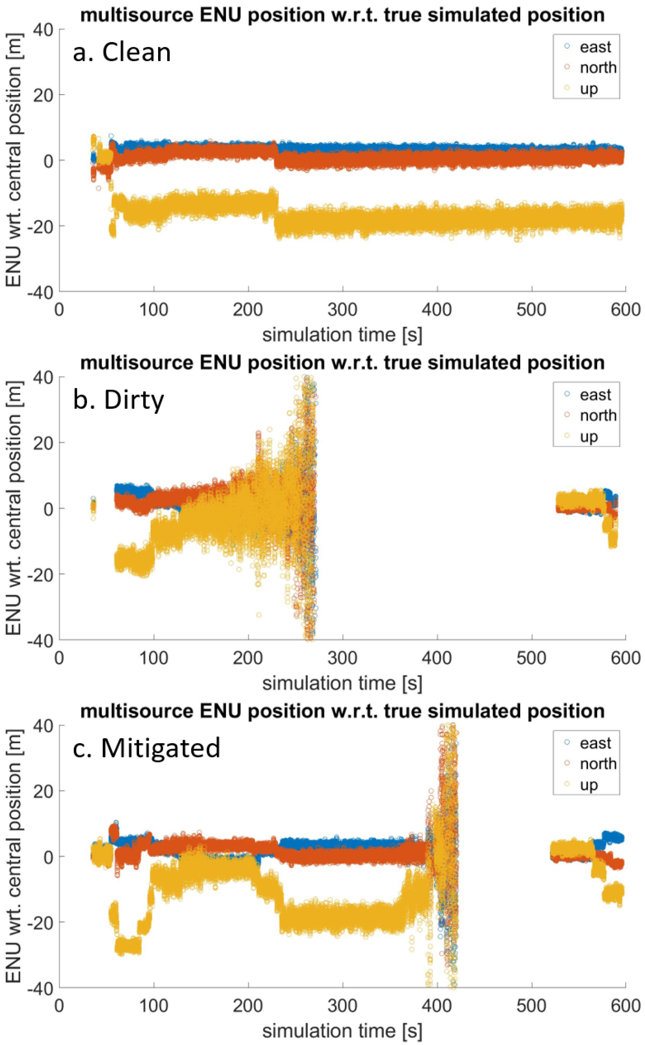
During the test phase, it was found that there is a significant offset (order of 30 m) between the position solution calculated from the clean lower L-band signals and the true position. This offset is not present for the upper L-band signals. The expected cause is a synchronization issue in the signal simulation process. To be able to interpret the PVT output of the multi-band receiver, the deviations of the PVT solution with respect to the true position of the clean signal is provided in
Figure 6a. The deviations of the PVT solution with respect to the true position obtained from the interfered signal and the mitigated signal are displayed in
Figure 6b,c. The prolonged period for which a PVT solution could be obtained in
Figure 6c indicates that the mitigation for this scenario was effective.
5.1. Dynamic Receiver
Apart from the static jamming scenarios that have been tested, the effect of dynamics on the effectiveness of this CRPA implementation can be studied using a comparison between the static chirp scenario and the dynamic chirp scenario in which the receiver had a constant velocity of 800 km/h with respect to the transmitter. It was observed that the CRPA detected and mitigated the interference on the lower L-band at a JSR of 9.62 dB and on the upper L-band at a JSR of 10.13 dB and applied mitigation when interference was detected. Mitigation of the interference allowed the satellite signals to continued to be tracked, but the robustness of the position solution for this particular scenario did not improve with respect to the interfered run. The mitigation does seem to be somewhat effective, but the effect of the high dynamics of this scenario should be studied in further detail.
5.2. Spoofing Scenarios
The original set of test scenarios included a repeater (meaconing) and a single satellite unsynchronized spoofing attack. In the test phase, it was observed that for the “dirty” signal, these scenarios were unable to spoof GNSS-SDR. Instead, the spoofing signal had a jamming-like effect. Therefore, no conclusions on the mitigation capability in the case of a successful spoofing attack can be made. It was observed that the MUSIC detected and mitigated the spoofing interference at an SSR of approximately 10.26 dB and applied mitigation when interference was detected. After mitigation was applied, the satellite signals continued to be tracked and the position solution was maintained for the entire duration of the scenario. Although a sophisticated spoofing attack could potentially spoof a receiver by using low SSR, the performed tests show that for higher-power spoofing attacks, the current CRPA implementation shows promising results. As CRPA is a precorrelator detection and mitigation technique, the detection and mitigation capabilities are expected to be independent of the effectiveness of the spoofing attack.
6. Discussion
Promising results confirm that the use of a CRPA antenna is an effective detection and mitigation method against most types of GNSS interference. There are, however, some topics that require extra attention via further study or adjustments in the test strategy.
Some of the tests were performed on a saturated input signal. Therefore, no reliable results on the maximum power that can effectively be mitigated are obtained. To determine the maximum jamming power for which the implementation under test is effective, the tests should be repeated with an unsaturated input signal.
A second issue encountered in the test campaign is the inconsistency between the used lower L-band and upper L-band signals. It is recommended to solve this issue for future tests, or to study the mitigation capabilities of the mitigation technique under test separately for the lower L-band and upper L-band signals (use a single-frequency receiver implementation for analysis).
The dynamic scenarios are particularly interesting for the aviation use case in which a CRPA is used as the aircraft GNSS antenna. The current implementation shows promising results where the satellite signals continued to be in track, but more research efforts should be given to the effect of high velocity (order of 800 km/h) on the mitigation performance.
In the selection of test scenarios for which the CRPA was tested, spoofing scenarios were included. Effective spoofing of a highly dynamic receiver is complicated and the spoofing scenarios were unsuccessful in spoofing the receiver. Although the results are promising as the CRPA is capable of mitigating the interference, tests with successful spoofing attacks should be performed in order to confirm the capability of the CRPA to mitigate such an attack.
Finally, the efficiency of the processing pipeline is limited by the file sizes of the required input data and tests take a significant amount of time. For future test campaigns, it is advised to be critical during the test scenario definition and to minimize the sample rate and scenario duration.
7. Conclusions
In this paper, the effectiveness of a software-based CRPA based on signal space decomposition for the detection and mitigation of different types of GNSS interference for civil aviation has been investigated. The algorithm under test is a modified version of the MUSIC algorithm, in which the gain of the central antenna element is kept constant, while the complex gains of the remaining three antenna elements are adjusted to place a null in the direction of the incoming interference signal. The proposed CRPA algorithm shows good results but has yet to be compared to alternative null-steering CRPA techniques, such as minimum variance distortionless response (MVDR) or linearly constrained minimum variance (LCMV) beamforming.
Initial results of the interference detection and mitigation tests show that this implementation is capable of detecting and mitigating jamming. Further study is required in order to make the detection and mitigation capabilities of the CRPA under test more robust. Although there is no definitive proof for the effectiveness of spoofing detection and mitigation, it is expected that the CRPA has a beneficial effect in the case of spoofing, as it agnostically detects and attempts to suppress the spoofing signal just like a jamming interference source. Further test with more complex spoofing scenarios should be performed in order to confirm this.
This study was conducted, specifically aiming at the detection and mitigation of GNSS interference in aviation. CRPAs are currently not used in the civil aviation sector, primarily due to their complexity, form factor, and export control limitations on certain specific technologies. There seems to be potential for further developments of CRPA for civil aviation, either as a standalone solution or in combination with other detection and mitigation measures investigated as part of the AIRING study [
7].
The software and simulation defined test method used in this project has proven to be a valuable platform for interference tests. It offers a highly controllable test environment, which can be used to systematically perform repetitive tests. Furthermore, it offers the opportunity to test interference detection and mitigation techniques for interferences not available for tests with Signal in Space (SiS). The flexibility in-test scenarios and CRPA setup offer an accessible research tool. However, it has to be kept in mind that the data volumes and processing times can form a considerable constraint on large test campaigns.
Author Contributions
Research, A.v.Z., J.-J.v.E., D.K., H.Z., F.D. and Y.K.; Paper writing draft, A.v.Z.; Review, H.Z. and Y.K. All authors have read and agreed to the published version of the manuscript.
Funding
This research was funded by the European Commission under contract DEFIS/2020/OP0006.
Institutional Review Board Statement
Not applicable.
Informed Consent Statement
Not applicable.
Data Availability Statement
Data are contained within the article. For access to the complete datasets please contact the authors.
Acknowledgments
The authors thank the project partners GMV, NLS, GMV-NSL, ENAIRE, and AXENTEK for their technical support and contributions in the AIRING project.
Conflicts of Interest
The authors declare no conflict of interest. The funder had no role in the design of the study; in the collection, analyses, or interpretation of data; in the writing of the manuscript; or in the decision to publish the results.
References
- European Union Aviation Safety Agency. Global Navigation Satellite System Outage Leading to Navigation/Surveillance Degradation. Saf. Inf. Bull. 2022, 2, 2022-02R1. [Google Scholar]
- International Telecommunication Union. Prevention of harmful interference to Radio Navigation Satellite Service Receivers in the 1559–1610 MHz frequency band. Circ. Lett. 2022, 488, CR/488. [Google Scholar]
- International Federation of Air Line Pilots. Communication Interference by Military Warships in the Pacific Region. 2023. Available online: https://www.ifalpa.org/media/3905/23sab03-communication-interference-by-military-warships-in-the-pacific-region.pdf (accessed on 1 October 2023).
- European Commission. Aviation Resilience to GNSS Frequency Jamming and Cyber Threats. In Invitation to Tender (Ares 4341987); DEFIS/2020/OP/0006; European Commission: Brussel, Belgium, 2020. [Google Scholar]
- Schmidt, R. Multiple emitter location and signal parameter estimation. IEEE Trans. Antennas Propag. 1986, 34, 276–280. [Google Scholar] [CrossRef]
- Zhang, J.; Cui, X.; Xu, H.; Lu, M. A two-stage interference suppression scheme based on antenna array for GNSS jamming and spoofing. Sensors 2019, 19, 3870. [Google Scholar] [CrossRef] [PubMed]
- GMV; NLR; NLS; GMV-NSL; ENAIRE; AXENTEK. Aviation Resilience to GNSS Frequency Jamming and Cyber Threats, Final Report; EC Project Report AIRING-GMV-FR; European Union: Brussel, Belgium, 2023. [Google Scholar]
| Disclaimer/Publisher’s Note: The statements, opinions and data contained in all publications are solely those of the individual author(s) and contributor(s) and not of MDPI and/or the editor(s). MDPI and/or the editor(s) disclaim responsibility for any injury to people or property resulting from any ideas, methods, instructions or products referred to in the content. |
© 2023 by the authors. Licensee MDPI, Basel, Switzerland. This article is an open access article distributed under the terms and conditions of the Creative Commons Attribution (CC BY) license (https://creativecommons.org/licenses/by/4.0/).


