Abstract
Low/zero-head cross-flow turbines (LZH-CFT) possess vast potential in the field of renewable energy technology. This research presents a modified design of a cross-flow turbine specifically engineered to harness the untapped hydro-kinetic energy from low/zero-head water resources. Unlike traditional hydro turbines, the LZH-CFT leverages a cross-flow configuration to utilize the water flows of natural streams, making it an ideal solution for flow channels with low/zero head. The design is modified through ANSYS simulations by varying the rotor’s blade angles (from 0 to 90°) and 60° angle is found optimum. The prototype model of modified design is prepared and tested, which represents 62.5% RPM efficiency and provides double power as compared to the typical cross-flow turbine.
1. Introduction
Hydraulic energy is one of the cleanest and most economical forms of energy, which can be obtained by installing multiple kinds of turbines including Pelton, Kaplan, and Francis turbines according to the required power, available head, and other parameters. The efficiency of the cross-flow turbine depends on various design parameters such as the number of blades, angles of attack, and inner-to-outer diameter ratios. Moreover, the availability of head is a critical parameter to attain and maintain the reasonable efficiency of the cross-flow turbine, which can be achieved through discharge regulator [1].
An attempt is made to utilize the micro-head of urban sewerage discharge water to produce hydro-power by modifying the design of a conventional cross-flow turbine through computational fluid dynamics (CFD) simulation [2]. Another study [3] is focused on exploiting the available micro-heads by modifying the design parameters of the cross-flow turbine to produce power. The design parameters (such as number of blades, runner dimensions, attack angle, etc.) of the cross-flow turbine are evaluated by Nasir [4] to achieve the maximum efficiency of the turbine.
Although numerous studies have been conducted covering various aspects of cross-flow turbines, there is a scarcity of research addressing the utilization of low/zero-head water streams for power generation. Therefore, the aim of this study is to use the flow velocity of a natural water stream and to transfer the kinetic energy of the water flow on the blades to achieve the maximum rotational velocity/revolutions per minute (RPM) of the turbine blades.
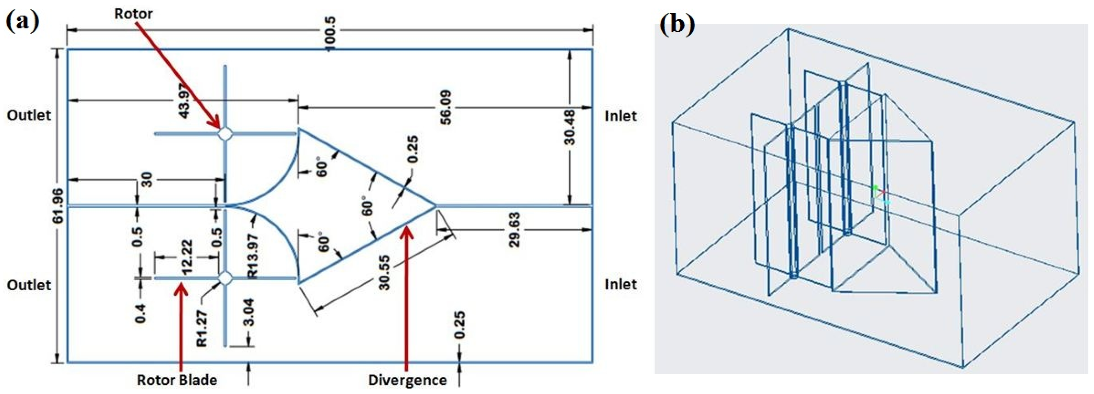
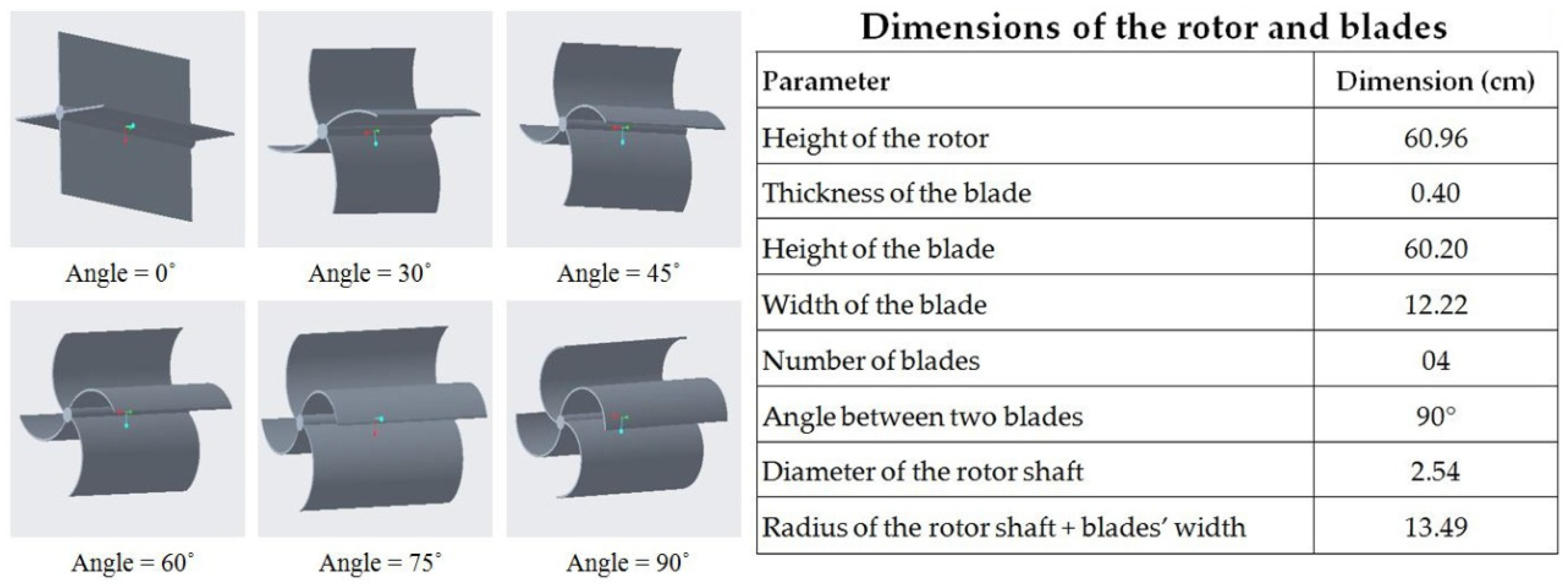
2. Methodology and Design
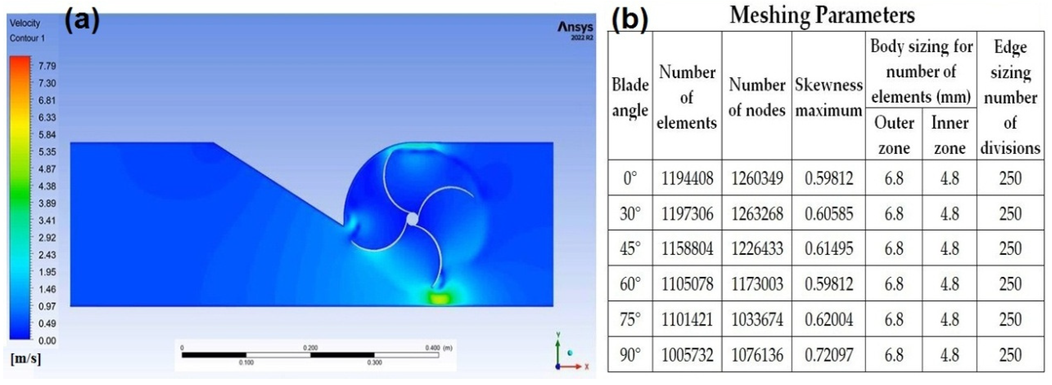
The velocity of the water stream was calculated by using the equation s = v × t and the noted average velocity of the water was 0.5094 m/s. The prototype model was designed in CREO parametric and a drawing of the basic design along with dimensions (cm) is shown in Figure 1a, while the wire frame 3D view is displayed in Figure 1b.
Figure 1.
Design of the prototype model: (a) 2D design along with dimensions, (b) 3D wire frame view.
The inlet channel was separated into two channels through a divergence of 60°, which reduced the inlet dimensions to half at the both edges of the divergence. As a result of the reduction in area by half computed through equation of continuity (A1 × V1 = A2 × V2), the inlet velocity (0.5094 m/s) was doubled and became 1.019 m/s at both edges of the divergence. This increased velocity can be used effectively to rotate the vertically placed (two) rotors after the divergence. To achieve maximum moment/torque, the angle of the rotor’s blades was varied from 0 to 90° curves as depicted in Figure 2. The dimensions (cm) of the rotor and blades are also displayed in Figure 2. The theoretical value of RPM of the rotor is 72, which was computed by dividing the velocity of the fluid (61.14 m/min) by the circumference of the rotor (0.8463 m).
Figure 2.
Design of the rotor and blades at various angles along with dimensions (cm).
ANSYS Simulation
The 3D geometry was created in the design modeler ANSYS Fluent and two types of meshing techniques were used (body sizing for the number of elements and edge sizing for the number of divisions between the inner and outer zones) as shown Figure 3b. In the setup, transient and k-epsilon were selected for turbulent flow, water was chosen from the library, and then we set 0.5 m/s as the inlet velocity along with 0 as the absolute pressure of the outlet. Mesh interfaces were generated between the inner and outer zones for the rotation of the rotor. Then, we set the hybrid initialization and 1500 iterations for all simulations to check the effect on rotors. Mesh independence was also checked in order to obtain optimum results.
Figure 3.
(a) Contour of simulation, (b) Meshing parameters and number of elements for different blade angles.
3. Results and Discussion
3.1. Simulation Results
Simulations were performed by varying the blade angle (0°, 30°, 45°, 60°, 75°, and 90°) to identify the blade angle for which the maximum moment can be achieved for preparation of prototype model. Figure 4a represents the simulation results in terms of moment, which shows that the blades at a 60° angle produce the maximum moment (24.5 N-m) among all the examined blade geometries. Figure 3a displayes the velocity contour of the simulation performed for 60° angle blades and demonstrates that the maximum velocity of the water is observed at the edge of the blade. The prototype model is prepared by setting the blades’ angle at 60°. The inlet and outlet sections of the prototype model are shown in Figure 4b and Figure 4c, respectively. By using the net moment (obtained from ANSYS simulations for 60° blade angle) and angular velocity, the net power is computed (by using P = T × ω), which is 128 W for one rotor and 256 W for both rotors.
Figure 4.
(a) Moment values measured through simulation for different blade angles, (b) Inlet of the prototype model, (c) Outlet of the prototype model.
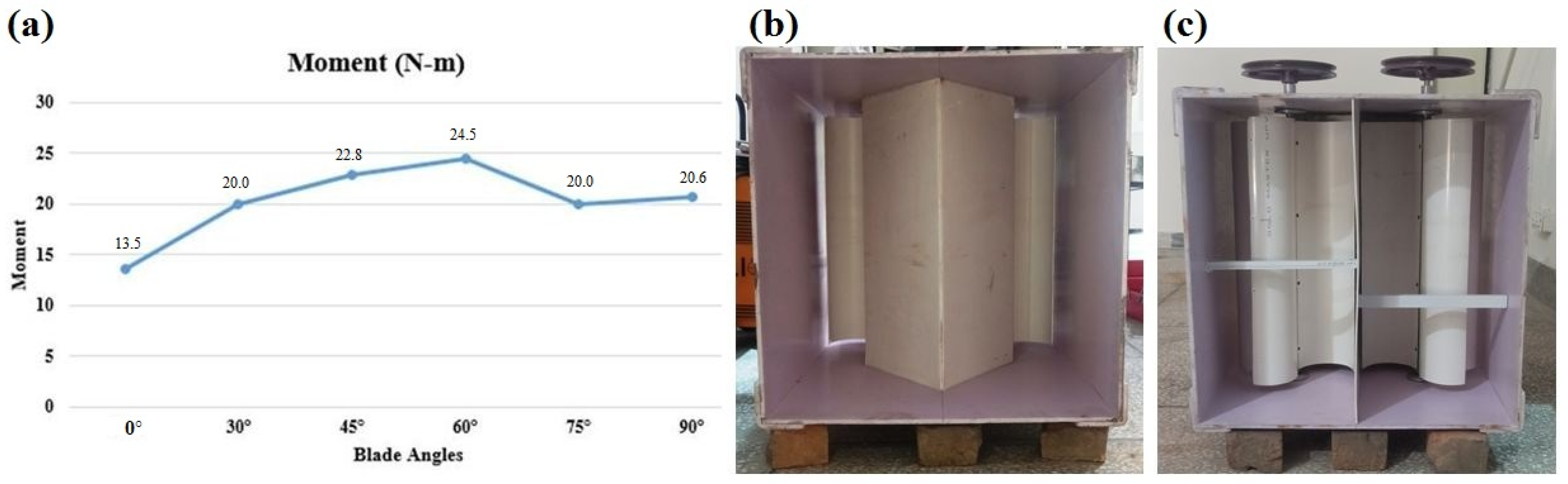
3.2. Experimental Results
After completing the prototype model shown in Figure 4b,c, the location selected for experimentation was Soan River near Chakiyan stop, Islamabad. As mentioned earlier, the measured velocity of water was 0.5 m/s, which was used to calculate the theoretical RPM (=72) and the same velocity (0.5 m/s) was used for all simulations. However, the initial location (where the velocity was measured) was changed due to some of the constraints (like available depth and volumetric flow) of the stream. The velocity of the water was again measured at the new location (Chakiyan stop) and the noted average velocity was 0.67 m/s instead of 0.5 m/s. By using the same previous steps, the new value of theoretical RPM was 96 for a 0.67 m/s velocity. The prototype was tested under modified flow conditions and both of its rotors attained a sTable 60 RPM. Based on the experimental results, the RPM efficiency (experimental value of RPM ÷ theoretical value of RPM) of the modified design of the turbine is 62.5% providing twice the power as compared to the general cross-flow turbine due to the double rotors.
4. Conclusions
In the present study, the design of a cross-flow turbine for a low/zero-head water stream is modified and evaluated through ANSYS simulations. The speed of the water is increased and doubled by placing a divergence in the inlet channel. The two vertically positioned rotors after the divergence utilize the increased speed of the water and effectively transform it into rotational velocity. The rotor’s blade angles are varied from 0 to 90° and the simulation results indicate that a 60° angle generates the maximum moment and power. The prototype model is prepared according to the optimum design parameters identified through simulations. The prototype is tested and shows stable performance with 62.5% RPM efficiency by providing twice the power as compared to the conventional cross-flow turbine.
Author Contributions
Conceptualization, methodology: G.A.; investigation, resources: A.A.; writing—original draft preparation: M.Z.A.; writing—review and editing: G.A.; visualization: M.F.; Supervision: G.A. All authors have read and agreed to the published version of the manuscript.
Funding
This research is funded by (NGIRI-2023-16887) National Gross-root ICT Research Initiative (NGIRI) 2022-23.
Institutional Review Board Statement
Not applicable.
Informed Consent Statement
Not applicable.
Data Availability Statement
The authors can provide relevant data on demand.
Conflicts of Interest
The authors declare no conflict of interest.
References
- Desai, V.R.; Aziz, N.M. An Experimental Investigation of Cross-Flow Turbine Efficiency. J. Fluids Eng. 1994, 116, 545–550. [Google Scholar] [CrossRef]
- MKhan, A.; Badshah, S. Research Article Design and Analysis of Cross Flow Turbine for Micro Hydro Power Application using Sewerage Water. Res. J. Appl. Sci. Eng. Technol. 2014, 8, 821–828. [Google Scholar]
- Chattha, J.A.; Khan, M.S.; Wasif, S.T.; Ghani, O.A.; Zia, M.O.; Hamid, Z. Design of a cross flow turbine for a micro-hydro power application. Power Conf. 2010, 49354, 637–644. [Google Scholar]
- Nasir, B.A. Design of high efficiency cross-flow turbine for hydro-power plant. Int. J. Eng. Adv. Technol. 2013, 2, 308–311. [Google Scholar]
Disclaimer/Publisher’s Note: The statements, opinions and data contained in all publications are solely those of the individual author(s) and contributor(s) and not of MDPI and/or the editor(s). MDPI and/or the editor(s) disclaim responsibility for any injury to people or property resulting from any ideas, methods, instructions or products referred to in the content. |
© 2023 by the authors. Licensee MDPI, Basel, Switzerland. This article is an open access article distributed under the terms and conditions of the Creative Commons Attribution (CC BY) license (https://creativecommons.org/licenses/by/4.0/).


