Abstract
The traditional valve train system consists of a spring mechanism with a specific level of stiffness. When compressing the spring, a significant amount of power is required. However, by replacing the conventional valve spring mechanism with a desmodromic valve system, the stiffness is reduced, leading to improved engine performance. This study analyzed the impact of this replacement on the engine’s performance and overall weight using finite element modeling. A comparative study was also conducted, which revealed that the desmodromic valve system generates a torque of more than 120 Nm, surpassing the 105 Nm produced by the traditional valve system. Furthermore, the weight of the desmo engine only increased by 2.75 kg.
1. Introduction
The internal combustion engine relies on precise valve timing for optimal performance [1]. Traditional cam-driven valve systems use springs to return the valves to their closed position after being opened by the camshaft lobes. However, these valve springs have certain limitations, especially at high engine speeds, which can lead to valve float and reduced performance [2]. In conventional cam-driven systems, the valve springs act as elastic components, providing the force necessary to close the valves. A higher spring stiffness results in a stronger force for a given valve displacement, while a lower stiffness leads to a weaker force [3]. At high engine speeds, the camshaft rotates rapidly, causing the valve to follow the cam profile closely during its opening phase. However, during the closing phase, the valve spring’s inertia and mechanical limitations can lead to valve bounce or float. Valve float occurs when the valve fails to close quickly enough, reducing the engine’s ability to maintain proper compression and combustion, ultimately limiting its performance [4]. A desmodromic valve system overcomes the limitations of conventional valve springs by eliminating the reliance on springs for valve closure. Instead, the desmodromic system uses two separate cams, one for valve opening and another for valve closing, ensuring precise control over the valve’s movement without relying on spring force. With a desmodromic system, the spring stiffness is not a limiting factor in achieving high engine speeds and performance. Since the valve closure is mechanically actuated using a separate cam, there is no reliance on spring forces to close the valves, eliminating the possibility of valve float [2]. This precise valve control allows for optimized valve timings, improved volumetric efficiency, and better combustion characteristics, contributing to enhanced power output, fuel efficiency, and reduced emissions. Ensuring the appropriate stiffness of the desmodromic actuation mechanism is essential to achieving accurate valve timing and reliable operation under various engine conditions [5].
In this work, a desmodromic valve system is designed for 4-stroke internal combustion engines. Unlike the standard valve system that utilizes a spring-loaded mechanism, the spring is replaced with two cam profiles for each valve in the desmodromic valve system. An end cam is incorporated into this valve system to prevent cam hop when used alongside a conventional valve system.
2. Methodology
2.1. FE Model and Meshing
For the analysis, 3D CAD models of both mechanisms had to be created. To accomplish this, MATLAB software was used, which takes inputs such as base circle diameter, lift, angles of rise and fall, and dwell angles, and then generates the cam profiles according to the chosen function. The resulting profile is then imported into SolidWorks to generate the 3D shape of the camshaft. For other parts, CREO software was employed to create their models by taking dimensions from the physically existing engine (HONDA D13B2) presented in Figure 1. The meshing of the part in ANSYS was carried out using a linear mechanical meshing approach with an average element size of approximately 2 mm. The resulting mesh comprised 10,207 nodes and 22,729 elements, ensuring a sufficient resolution to capture the intricate features and complexities of the parts’ geometry. To validate the mesh quality, a series of convergence tests were conducted, ensuring that the simulation results remained consistent and independent of the mesh refinement.
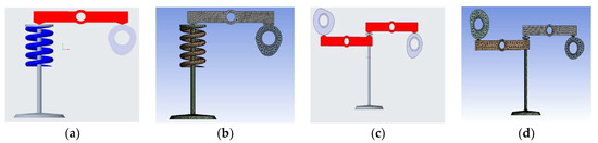
Figure 1.
(a,b) Geometry and meshing of traditional valve system. (c,d) Geometry and meshing of desmodromic valve system.
2.2. Boundary Conditions
In the FE analysis of the desmodromic valve train, frictionless contact regions are considered. Figure 2a,b illustrates the applied boundary conditions for both mechanisms.
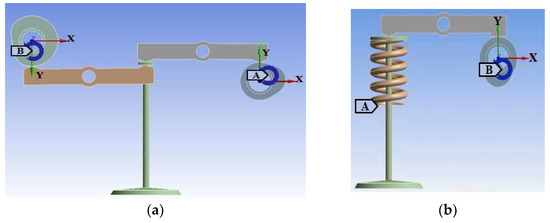
Figure 2.
(a) Boundary conditions for desmodromic valve system and (b) for traditional valve system.
The connections between the ground and camshaft, as well as the rocker arms, allow for rotational movement, while the connection between the valve and ground enables linear motion. A rotational velocity of 1 rad/s is used to simulate the camshaft’s rotation. Similarly, the traditional valve train mechanism also assumes frictionless contact regions and employs revolute joints between the ground, camshaft, and rocker arm. The spring is supported at the bottom and connected to the valve at the upper end.
2.3. Regular and Desmodromic CAM Profiles
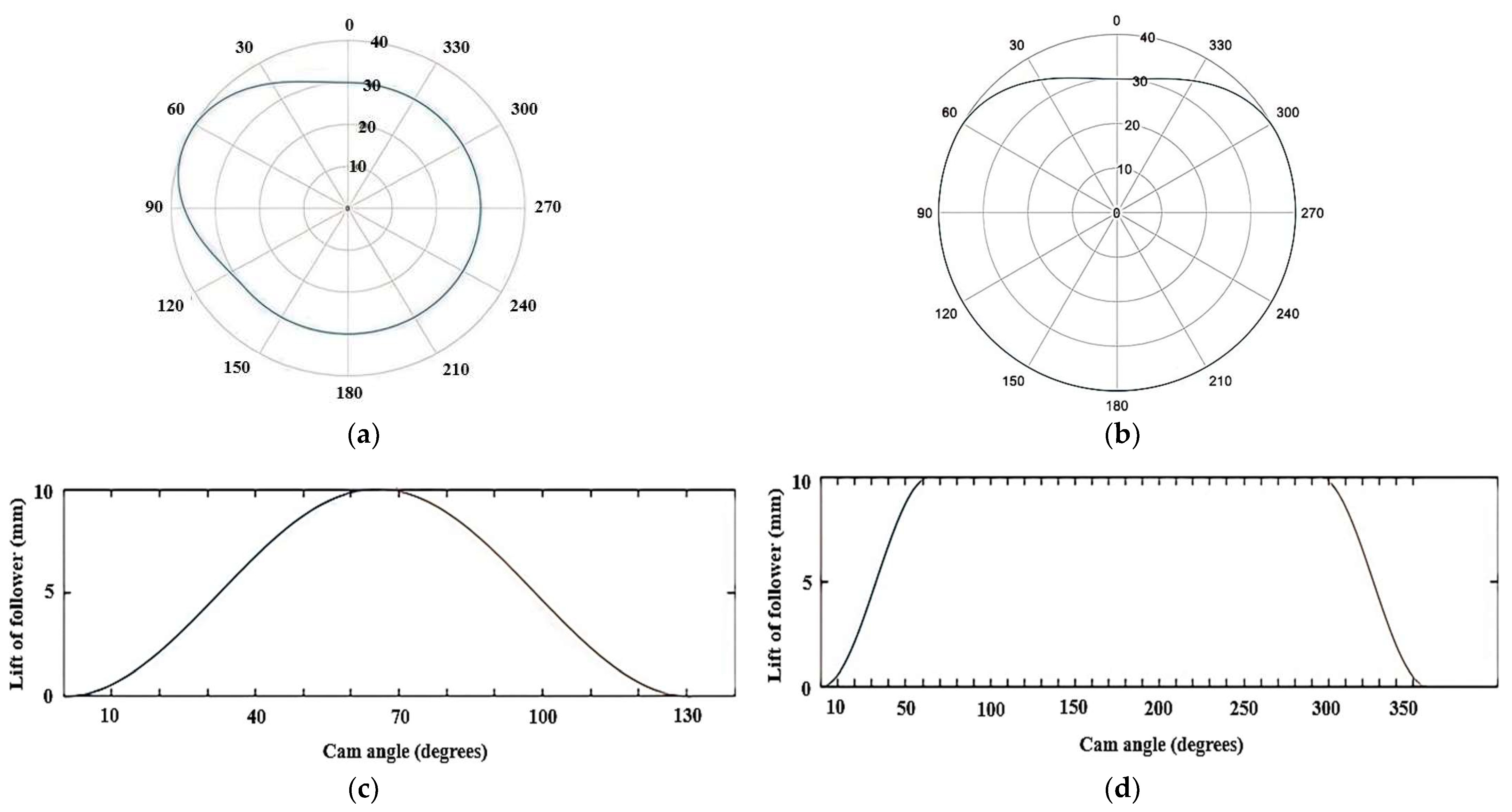
The regular cam shape (Figure 3a,c), which is capable of opening and closing the valve using a single cam, was generated using MATLAB code. During the rise phase of a standard cam mechanism, the lift angle is 65 degrees, and the duration of lift is 1 unit. Similarly, during the fall phase, the lift angle is 65 degrees, and the duration of lift is 229 units. In a desmodromic cam mechanism (Figure 3b,d), the ascent angle is 65 degrees, and the dwell period during the rise phase is 229 units. Similarly, the descent angle is 65 degrees, and the dwell period during the fall phase is 1 unit.

Figure 3.
(a) Regular CAM profile; (b) desmodromic CAM profile; (c) lift vs. CAM angle for regular CAM and for (d) desmodromic valve mechanism.
3. Results and Discussion
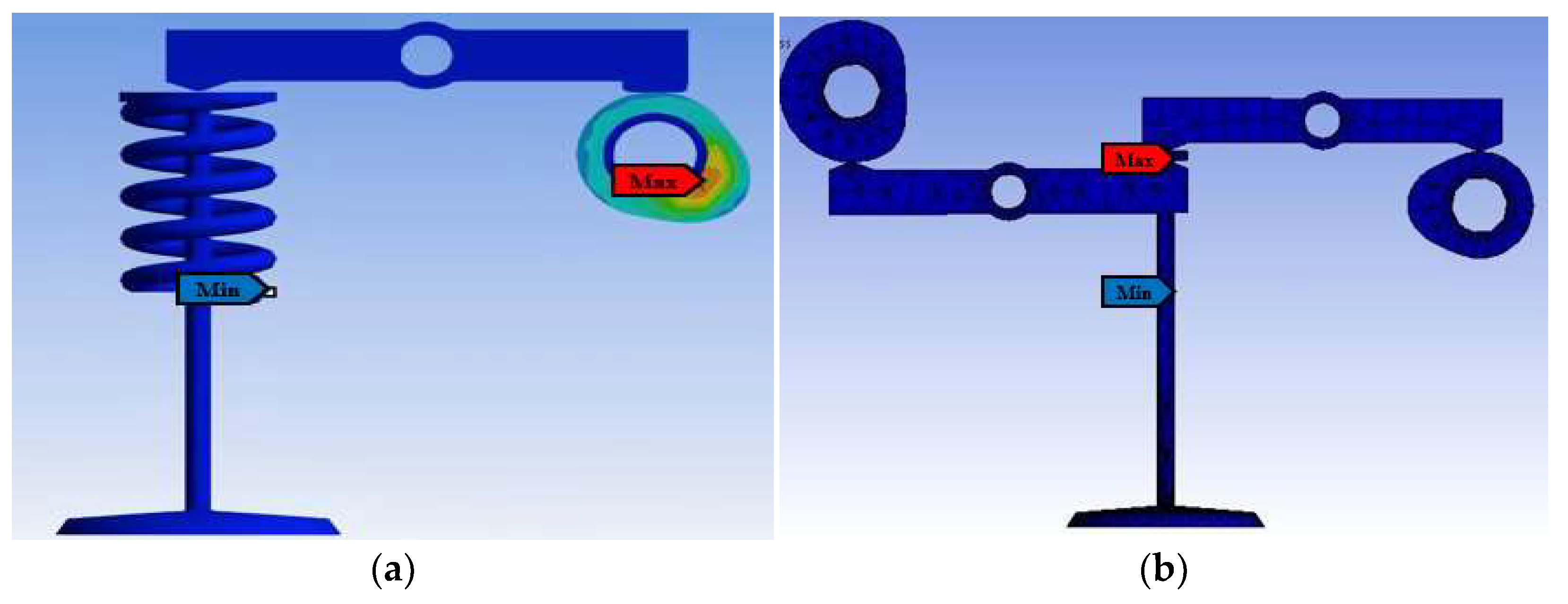
In the case of the conventional valve mechanism, there are two primary locations shown in Figure 4 where stresses occurred: the lower end of the spring and the base circle of the cam profile. Upon analysis, the maximum stress observed at these points was found to be 3.3566 × 10⁻⁶ MPa, while the minimum stress recorded was 2.5399 × 10⁻¹⁹ MPa. Within the desmodromic valve system, stress was distributed across various components such as the rocker arms and cam profiles. However, the valve stem bore the highest stress levels. With a maximum stress of 113.56 MPa and a minimum stress of 3.9438 × 10⁻¹¹ MPa, it is imperative for the valve stem to exhibit sufficient strength to withstand these stresses and avoid any deformation or failure. When comparing the engine torque, the traditional valve system produced an engine output torque of 105 Nm, while the desmodromic valve system generated 120 Nm, which was calculated by considering the forces acting on the system and the moment arms associated with those forces. The mass of engine was increased by only 2.75 kg using the desmodromic valve mechanism instead of the traditional spring-based mechanism.
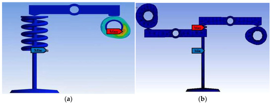
Figure 4.
(a) Equivalent stresses for traditional valve system and for (b) desmodromic valve system.
4. Conclusions
It is evident that the desmodromic valve system offers advantages over the spring valve system. The stress on the rocker arm was reduced to −0.127785 MPa from 8.774 × 10⁻⁴ MPa (conventional mechanism), and the engine torque was increased to 120 Nm. Lower stress levels were typically experienced by the desmodromic spring-less valve system in comparison to a regular valve system. This is due to the elimination of valve float at high engine speeds, preventing excessive stress on the valve components. Precise and consistent valve opening and closing are ensured by the direct mechanical linkage in the desmodromic system, thereby minimizing the chances of valve impacts or collisions.
Author Contributions
Conceptualization; S.R., M.H. and Z.I.; methodology; S.R., M.I. and U.B.R.; formal analysis; M.H. and S.R.; investigation; M.H., D.H. and M.I.; data curation; Z.I., U.B.R. and D.H.; writing—original draft preparation; S.R., D.H. and U.B.R.; writing—review and editing; M.H. and M.I.; supervision; M.H. and S.R.; All authors have read and agreed to the published version of the manuscript.
Funding
This research received no external funding.
Institutional Review Board Statement
Not applicable.
Informed Consent Statement
Not applicable.
Data Availability Statement
Not applicable.
Conflicts of Interest
The authors declare no conflict of interest.
References
- RDahham, Y.; Wei, H.; Pan, J. Improving Thermal Efficiency of Internal Combustion Engines: Recent Progress and Remaining Challenges. Energies 2022, 15, 6222. [Google Scholar] [CrossRef]
- Rahul, W.; Sourabh, S.; Swapnil, S.; Nikhil, J. Study of Design & Manufacturing of Cam Operated Spring Less Valve System for IC Engine. IJSRDV 2020, 7, 385–388. [Google Scholar]
- Zewen, G.; Xiaonan, H.; Elspeth, K.; Jianqiao, Y. Non-linear finite element model for dynamic analysis of high-speed valve train and coil collisions. Int. J. Mech. Sci. 2020, 173, 105476. [Google Scholar]
- Gu, Z. Static and Dynamic Analysis of Nonlinear Valve Springs Based on Finite Element Analysis and Machine Learning Algorithm. Ph.D. Thesis, Lancaster University, Lancaster, UK, 2022; p. 201. [Google Scholar]
- Hu, B.; Li, Y.; Yin, L. Theoretical and Experimental Analysis of Dynamic Characteristics for a Valve Train System. Sensors 2021, 21, 6328. [Google Scholar] [CrossRef]


Disclaimer/Publisher’s Note: The statements, opinions and data contained in all publications are solely those of the individual author(s) and contributor(s) and not of MDPI and/or the editor(s). MDPI and/or the editor(s) disclaim responsibility for any injury to people or property resulting from any ideas, methods, instructions or products referred to in the content. |
© 2023 by the authors. Licensee MDPI, Basel, Switzerland. This article is an open access article distributed under the terms and conditions of the Creative Commons Attribution (CC BY) license (https://creativecommons.org/licenses/by/4.0/).