Proceeding Paper

Increasing the Efficiency of the Information Management System for Controlling the Spatial Orientation of Objects in Geophysical Research †

Department of Computer Systems, Institute of artificial intelligence and robotics, Odessa Polytechnic National University, Av. Shevchenko 1, 65044 Odessa, Ukraine
*
Author to whom correspondence should be addressed.
Presented at the International Conference on Electronics, Engineering Physics and Earth Science (EEPES’23), Kavala, Greece, 21–23 June 2023.
Eng. Proc. 2023, 41(1), 5; https://doi.org/10.3390/engproc2023041005
Published: 13 July 2023

Abstract

:
The issue of increasing the efficiency of the information-control system for monitoring the spatial orientation of objects in geophysical surveys by improving the filtering of sensor signals in the stationary part of the system is considered in this study. For this purpose, an approach is proposed to reduce the bandwidth when connecting bandpass filters of the same type in series. Ratios are obtained that allow one to accurately determine frequencies and bandwidth.

Published: 13 July 2023

1. Introduction

Geophysical methods of well research based on modern physical methods of rock research are used to study the geological structure of the subsoil according to well sections, identify and evaluate hydrocarbon reserves, and use field geophysical information in the design, control and analysis of oil and gas field development and the technical condition of wells. In recent years, new methods for the geophysical exploration of wells have been developed and modern geophysical equipment has being introduced everywhere, which makes it possible to quickly perform the complex processing and interpretation of production and geophysical information using computer technology employing the latest hardware and software [1,2].
Necessity determines the orientation parameters of wells drilled in environments with anomalous magnetic properties, with steel pipes employed when restoring old deposits, when examining ore wells, when monitoring pipelines laid in hard-to-reach places, when building various underground facilities, as well as when controlling landslide zones, bulk soil dams, tunnels, walls of pits and mine shafts andwhen controlling settlement in the foundations or embankments of complex structures, such as nuclear power plants, leading to the expediency of using inclinometers.
The problem of underground orientation is solved with the help of inclinometric systems (IS), which are information-measuring complexes consisting of technical means, methodological and mathematical support [3,4,5].
The modern development of information and control systems for industrial production is based on the concept of Industry 4.0. Computerization and informatization of many research processes and industrial production has led to the emergence of the Industrial Internet of Things (IIoT) [6].
This direction allows one to significantly automate all processes by supplying equipment with multifunctional sensors, actuators and controllers. The collected data are processed and sent to the appropriate services, which allows the staff to quickly make informed and informed decisions. However, the ultimatetask is to reach a level where smart systems can work without the participation of people. The role of personnel in this case is reduced to monitoring the operation of systems and responding only to emergency situations to ensure safety and reliability [6,7,8]. The presence of wireless networks and cloud technologies contributes to the rapid collection of data, which, after primary processing, are sent to the analysis and decision center. Further development of such systems follows the direction of the humanization of decision-making and friendly contact with people in accordance with the concept of Industry 5.0 [9].
In the general case, a computer information and control system for controlling the spatial orientation (CICS CSO) of objects can be represented in the form of a block diagram, as seen in Figure 1.
The structural diagram of the CICS includes a dynamic part and a stationary part. The transfer of information between these parts is carried out via the communication link. Projections of free fall, the Earth’s magnetic field, measuring transducers are transmitted via the communication link to the stationary part. In the stationary part, the rotation angle of the object orientation is calculated, using the zenith angle θ , the sighting angle ϕ , and the azimuth angle α .
To increase the efficiency of the CICS CSO and control the measurement process, as well as to increase the reliability of the system, it is necessary to have devices in the stationary part of signal reception that can operate in difficult signal-jamming conditions. Under these conditions, the frequency-dependent components (FDC) of the signal reception path, based on software and hardware, are easily controlled to rebuild the main characteristics, which can improve the accuracy of extracting the information signal from the sensor. To receive a modulated signal at the stationary part, it is necessary to have a bandpass-type FDC with the possibility of tuning the main frequency, the receiving band and the steepness of the AFC. It is difficult to manage such high-order components, because many of the transfer function coefficients of the components are interconnected [10,11,12,13,14]. Therefore, in most cases, for the control of characteristics, various compounds of the low-order FDC are used [15,16], due, for example, to the serial connection of the same type of low-order FDC. This has an impact on both manageability and reliability. It also facilitates and simplifies the rearrangement of the component [17,18].
As a low-order component, components of the first and second order are more often used. Typical tasks include changing the cutoff frequency, component bandwidth, and increasing the steepness of the amplitude–frequency characteristics (AFC) slope. It should be noted that the general concept of frequency-dependent components of a computer system includes both typical links of control systems and filters.
We consider a series connection of the same type of second-order components to increase the steepness of the AFC slope, since the issues regarding tuning the cutoff frequency are considered in [19].

2. Serial Connection of the Same Type Components and Their Effect on the Frequency Characteristics

When the transfer functions of the same type of component are connected in series, their transfer functions are multiplied. Since the transfer function H 0 p consists of amplitude–frequency characteristics (AFC) and phase frequency characteristics (PFC), if the components are the same, we can write that:
H 0 j ω = H 0 ω · e j φ 0 ( ω )
where H 0 ω   a n d   φ 0 ω are the amplitude–frequency and phase–frequency characteristics of the main components of the same type, respectively.
Multiplication of the transfer functions corresponds to exponentiation for components of the same type which are connected in series.
H p = i = 1 n H i p = H 0 ( p ) n
The AFC and PFC are transformed as follows:
H j ω = H 0 ( J ω ) n = H 0 ( ω ) n · e j n φ 0 ( ω )
Therefore, the main changes occur in the AFC.
The aim of the work is to develop a new approach to the calculation of the series connection of the same type of frequency-dependent components to improve the efficiency of the information-control system inmonitoring the spatial orientation of objects in geophysical research by reducing the bandwidth and increasing the steepness of the AFC in the stationary part of the system. For the sake of an example, we look at bandpass digital filters because they are widely used in the processing cycles of sensor signals under complex interference and signal conditions.

3. Increasing Steepness of the AFC of the Digital Bandpass Filters

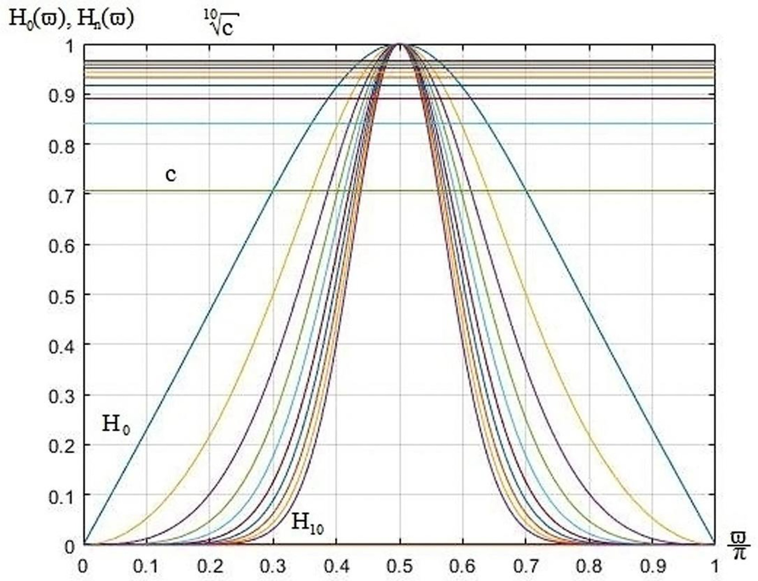
When connecting the same type of bandpass filter in series, the AFC of the new connection is compressed, as it were, while the cutoff frequencies are shifted to the center frequency and the AFC steepness increases, as shown in Figure 2.
The transfer function of the main bandpass filter is mathematically described as follows:
H z = a 0 + a 1 z 1 + a 2 z 2 1 + b 1 z 1 + b 2 z 2 ,
where a 0 , a 1 , a 2 , b 1 , a n d   b 2 are the real coefficients of the numerator and denominator, respectively.
Through substitution of z 1 = e j ϖ , where ϖ is the normalized angular frequency and ϖ = 2 π f f d and ϖ 0 , π , f , f d are linear frequency and sampling frequency, respectively, we obtain a complex transmission coefficient, and on its basis the AFC at a 0 = a 2   a n d   a 1 = 2 . After the transformation, the square of the AFC can be written as:
H 2 ϖ = 2 a 0 s i n ϖ 2 1 b 2 2 + b 1 2 + 2 b 1 1 + b 2 c o s ϖ + 4 b 2 c o s 2 ϖ .
It should be noted that the peak frequency of the AFC does not change in this case and is determined by the equation, as shown in Figure 2:
ϖ p = arccos b 1 1 + b 2 .
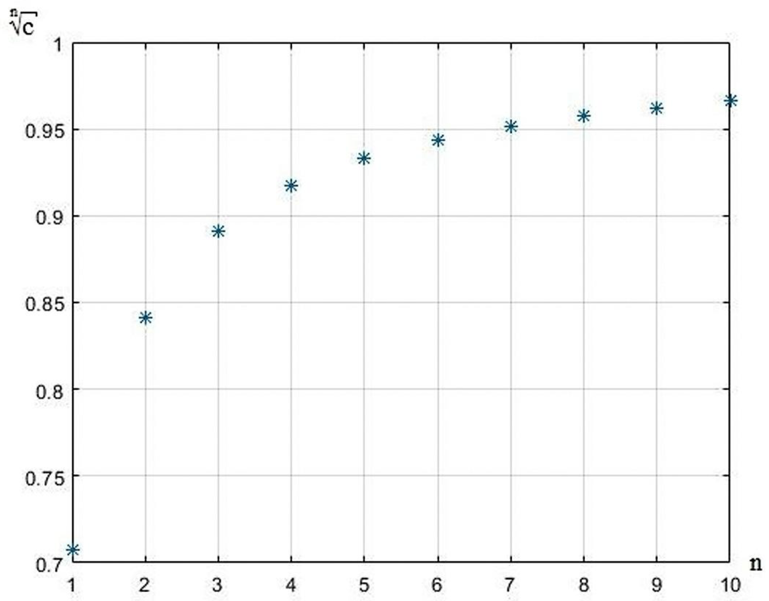
Usually, the level at which the cutoff frequency is determined is c = 0.707 , i.e., H ϖ c = c , where ϖ c is the cutoff frequency of the AFC at level c . When multiplying the same type of frequency response or raising its degree, the level remains the same, but in order to determine the cutoff frequencies of the new AFC, when they are connected in series, it is necessary to extract the root of the corresponding order from the level c , i.e., c n , as seen in Figure 3. In Figure 2, these levels are shown with horizontal lines.
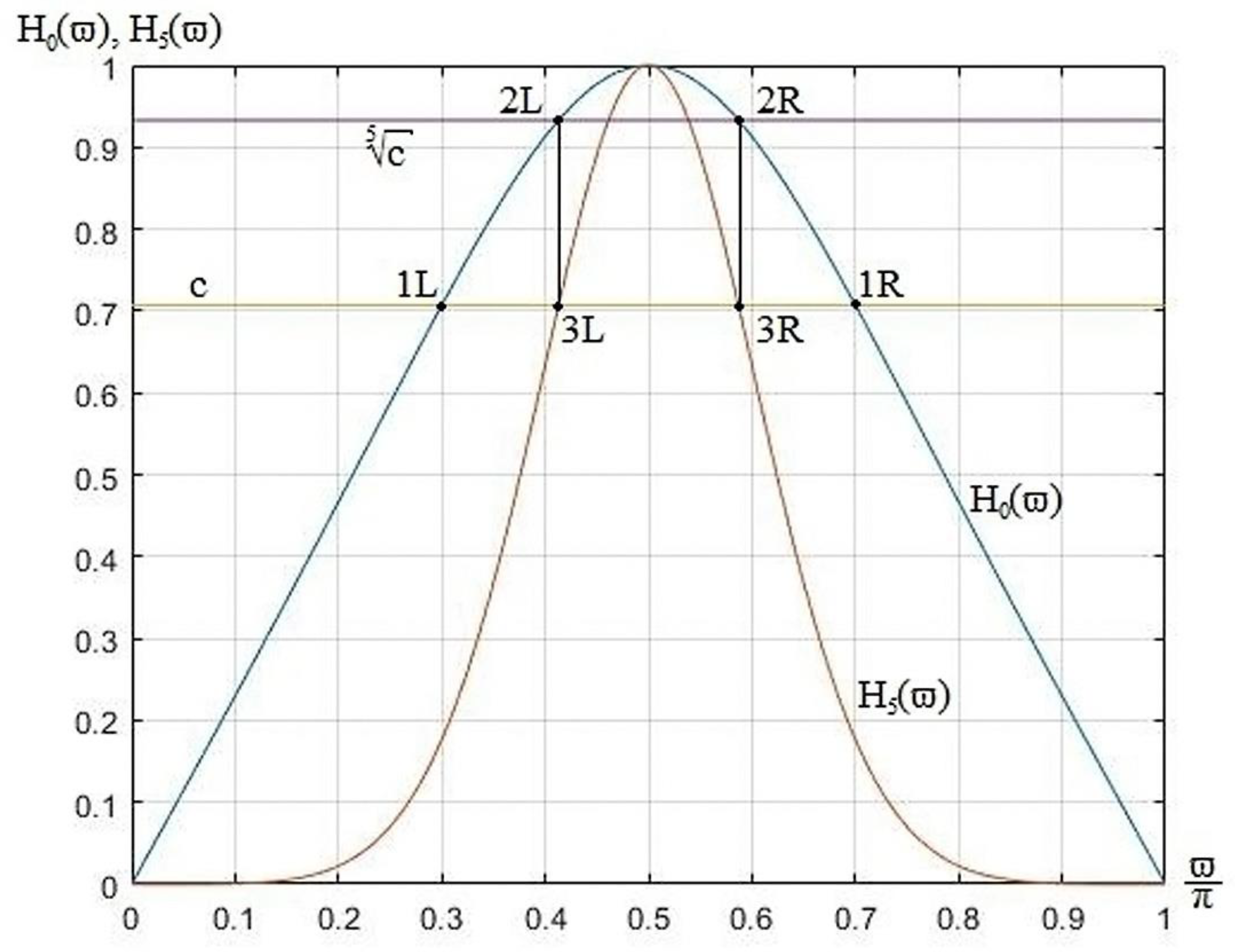
In this case, the AFC of the main filter can be used to calculate the cutoff frequencies of the new AFC (Figure 4).
Figure 4 shows the correspondence between the cutoff frequencies of the main AFC of the second order at the level c and the AFC when five of the same type of AFC of the second order are connected in series. These cutoff frequencies are determined by the main AFC, the parameters of which are known, and the new level.
To determine the cutoff frequencies of the new AFC after connecting n filters of the same type according to the main AFC, it is necessary to solve the following equation:
H 2 ϖ = 2 a 0 s i n ϖ 1 n 2 1 b 2 2 + b 1 2 + 2 b 1 1 + b 2 c o s ϖ 1 n + 4 b 2 c o s 2 ϖ 1 n = c 2 n = c 2 n
where ϖ 1 n is the cutoff frequency at a new level c n on the main AFC.
Solving this equation, provided that [10]
a 0 = 1 b 2 2
found formulas for determining the cutoff frequencies for the n-th connection of the same type of filter. To simplify the representation of the result, we introduce new notation:
A = 4 b 2 c 2 n + 1 b 2 2
B = b 1 1 + b 2 c 2 n
C = 1 b 2 1 c 2 n 4 b 2 b 1 2 c 2 n + 1 b 2 2
As a result, we obtain the cutoff frequencies of the AFC with the n-th connection of the same type of filter (Figure 5).
ϖ c n 1 = a r c c o s ( B + C A )
ϖ c n 2 = a r c c o s ( B C A )
In accordance with the formulas obtained, it is possible to determine the bandwidth of such a compound as ϖ B P = ϖ c n 1 ϖ c n 2 (Figure 6). As can be seen from Figure 6, the bandwidth decreases exponentially.
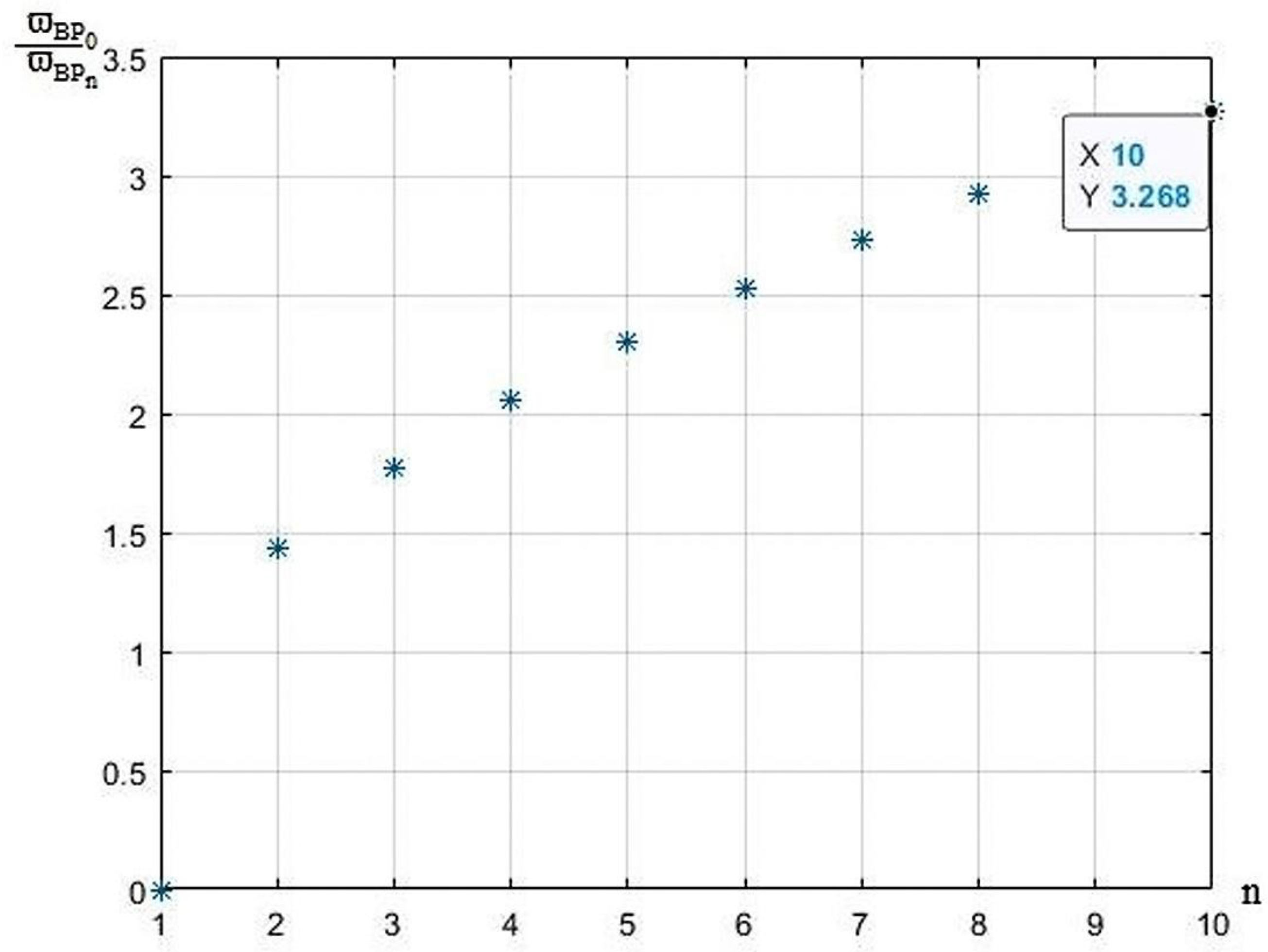
In this case, it can be seen how many times the bandwidth will decrease with a serial connection (Figure 7).
For example, when connecting four components of the same type, the bandwidth is reduced by more than two times; with eight, it is reduced by almost three times; and with ten, the bandwidth is reduced by 3.27 times.

4. Conclusions

The serial connection of frequency-dependent components of the same type leads to the exponentiation of both the transfer function and the AFC. This leads to a decrease in the bandwidth with increasing steepness of the AFC.
While analyzing the AFC of a serial connection of the same type of components, a new approach was obtained to obtain accurate values of cutoff frequencies and bandwidth.
The obtained ratios lead to an increase in filtering in the stationary part of the information-control system for controlling the spatial orientation of objects. It should be noted that this approach makes it possible to automatically increase the operational security of sensor signal processing in the presence of interference in accordance with the Industry 4.0 concept.

Author Contributions

T.S.: investigation, software, original draft preparation, visualization; A.B.: investigation, software; V.S.: conceptualization, methodology, project administration, supervision; O.S.: validation, data curation; P.S.: validation, review and editing. All authors have read and agreed to the published version of the manuscript.

Funding

This research received no external funding. It was done in area of department work.

Institutional Review Board Statement

Did not require ethical regulation.

Informed Consent Statement

Did not involve humans.

Data Availability Statement

Based on “Integrated improvement of the efficiency of computer control system of spatial orientation settings of drilling facilities” (https://doi.org/10.33271/nvngu/2022-1/116). The current work is the next step in this area. This is fist publication in this new range.

Conflicts of Interest

The authors declare no conflict of interest.

References

  1. Erkan, K. A Comparative Overview of Geophysical Methods; The Ohio State University: Columbus, OH, USA, 2008; Geodetic Science and Surveying, Report No. 488; Available online: https://core.ac.uk/download/pdf/159585702.pdf (accessed on 30 September 2008).
  2. Erkan, K.; Jekeli, C. A comparative analysis of geophysical fields for multi-sensor applications. J. Appl. Geophys. 2011, 74, 142–150. [Google Scholar] [CrossRef]
  3. Logging While Drilling (LWD) & Measurements While Drilling (MWD). Schlumberger Limited. 2014. Available online: http://www.slb.com/services/drilling/mwd_lwd.aspx (accessed on 17 April 2014).
  4. Scientific Drilling International. Available online: http://www.scientificdrilling.com/ (accessed on 14 December 2022).
  5. Measurements While Drilling (MWD). Available online: http://www.slb.com/services/drilling/mwd_lwd/mwd.aspx (accessed on 21 March 2021).
  6. Grangel-González, I.; Rivas, P.J.B.; Halilaj, L.; Lohmann, S. The Industry 4.0 Standards Landscape from a Semantic Integration Perspective. In Proceedings of the IEEE 22nd International Conference on Emerging Technologies and Factory Automation (ETFA), Limassol, Cyprus, 1–15 September 2017. [Google Scholar] [CrossRef]
  7. Santos, B.P.; Charrua-Santos, F.; Lima, T.M. Industry 4.0: An overview. In Proceedings of the World Congress on Engineering 2018 Vol II WCE, London, UK, 4–6 July 2018; Available online: https://www.researchgate.net/publication/326352993_Industry_40_an_overview (accessed on 6 July 2018).
  8. Industry 4.0. Available online: https://www.cognex.com/ru-ru/what-is/industry-4-0-machine-vision/development (accessed on 3 October 2021).
  9. Adel, A. Future of industry 5.0 in society: Human-centric solutions, challenges and prospective research areas. J. Cloud Comput. 2022, 11, 40. [Google Scholar] [CrossRef] [PubMed]
  10. Mao, J.; Choi, W.; Tam, K.; Che, W.; Xue, Q. Tunable bandpass filter design based on external quality factor tuning and multiple mode resonators for wideband applications. IEEE Trans. Microw. Theory Tech. 2013, 61, 2574–2584. [Google Scholar] [CrossRef]
  11. Rais-Zadeh, M.; Fox, J.; Wentzloff, D.; Gianchandani, Y. Reconfigurable radios: A possible solution to reduce entry costs in wireless phones. Proc. IEEE 2015, 103, 438–451. [Google Scholar] [CrossRef]
  12. Schuster, C.; Wiens, A. Performance Analysis of Reconfigurable Bandpass Filters with Continuously Tunable Center Frequency and Bandwidth. IEEE Trans. Microw. Theory Tech. 2017, 65, 4572–4583. [Google Scholar] [CrossRef]
  13. Dhabu, S.; Ambede, A.; Smitha, K.G.; Darak, S.; Vinod, A.P. Variable Cutoff Frequency FIR Filters: A Survey. SN Appl. Sci. 2018, 2, 1–23. [Google Scholar] [CrossRef] [Green Version]
  14. Koshita, S.; Abe, M.; Kawamata, M. Recent Advances in Variable Digital Filters. In Digital Systems; IntechOpen Limited: London, UK, 2018. [Google Scholar] [CrossRef] [Green Version]
  15. Prabhakar, S.; Sappal, A.S. Characteristics of Tunable Digital Filters. Int. J. Adv. Res. Comput. Sci. Softw. Eng. 2013, 3, 362–369. [Google Scholar]
  16. Widely Tunable and Highly Reconfigurable Filters. Available online: https://engineering.purdue.edu/IDEAS/TunableFilters.html (accessed on 7 May 2011).
  17. Haridas, N.; Elias, E. Efficient variable bandwidth filters for digital hearing aid using Farrow structure. J. Adv. Res. 2016, 7, 255–262. [Google Scholar] [CrossRef] [PubMed] [Green Version]
  18. Zahoor, S.; Naseem, S. Design and implementation of an efficient FIR digital filter. Electr. Electron. Eng. 2017, 4, 34–46. [Google Scholar] [CrossRef]
  19. Zhyvtsova, L.I.; Ukhina, H.V.; Sytnikov, V.S.; Streltsov, O.V.; Stupen, P.V. Integrated improvement of the efficiency of computer control system of spatial orientation settings of drilling facilities. Nauk. Visnyk Natsionalnoho Hirnychoho Universytetu 2022, 1, 116–122. [Google Scholar] [CrossRef]
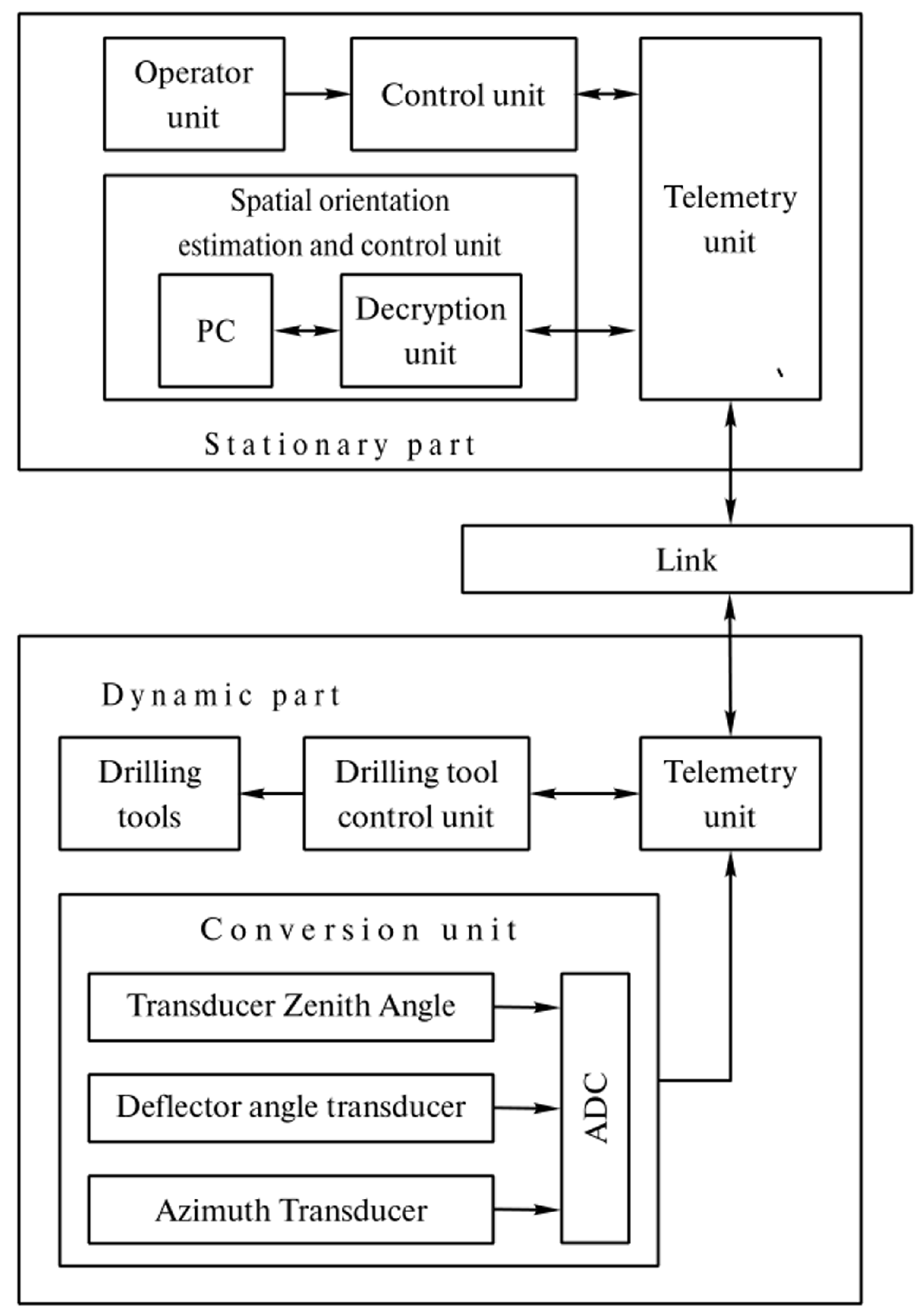
Figure 1. Structural diagram of a computer information-control system for monitoring the spatial orientation of objects in geophysical research.
Engproc 41 00005 g001
Figure 2. AFC of digital second-order Butterworth bandpass filters when they are connected in series. Where H 0 —AFC of the first order, H 10 —AFC of the 10th order, c —the level of the cutoff frequency, c 10 —the level of the cutoff frequency of the 10th order.
Engproc 41 00005 g002
Figure 3. Graph of the cutoff level’s dependence on the number of connected filters of the same type.
Engproc 41 00005 g003
Figure 4. AFC of the main Butterworth filter of the second order and AFC with five similar second-order Butterworth filters of the same type are connected in series. Where H 0 ( ϖ ) —AFC of the first order, H 5 ( ϖ ) —AFC of the 5th order, c —the level of the cutoff frequency, c 5 —the level of the cutoff frequency of the 5th order. Projection 2L and 2R points of the 1st order to 3L and 3R points of the 5th order respectively. 1L and 2R are basical cutoff frequency of the first order.
Engproc 41 00005 g004
Figure 5. Graph of the dependence of the cutoff frequencies when the same types of filter are connected in series on the number of connections.
Engproc 41 00005 g005
Figure 6. Bandwidth plot ϖ B P from the number of connections.
Engproc 41 00005 g006
Figure 7. Bandwidth reduction plot ϖ B P from the number of connections.
Engproc 41 00005 g007
Disclaimer/Publisher’s Note: The statements, opinions and data contained in all publications are solely those of the individual author(s) and contributor(s) and not of MDPI and/or the editor(s). MDPI and/or the editor(s) disclaim responsibility for any injury to people or property resulting from any ideas, methods, instructions or products referred to in the content.